If you have ever encountered the installation and configuration of computer networks, then you probably know how important it is to have a crimper on hand that will allow you to quickly attach connectors to an Ethernet cable to connect it to a computer. If this is your first time encountering this, then you may not know anything about the crimper. Today we will tell you how to crimp an RJ-45 cable with your own hands using this tool and without it. The material will certainly be useful to many readers.
How to crimp an RJ-45 cable with your own hands
What does twisted pair and Wi-Fi have to do with it?
Dear reader, I have a free blog here - so if everything is not interesting, immediately scroll through the Contents to the sections of the article that interest you. I'll start from afar. In a galaxy far, far away...
The fact is that the central element of a home Wi-Fi network is now a router. A modern router usually has wired connections:
- From the router to the provider's network - the same cable from the entrance. There is regular Ethernet and telephone under ADSL - all these wires are called “twisted pair”. The first occurs more often, the second less and less often.
- From a router to a computer or laptop - sometimes the connection is made not via Wi-Fi, but via wire. Likewise, computers without an adapter can be connected to the Internet, and seasoned players say the ping will be better.
So in a home network there is nowhere without a twisted pair cable.
Application area
Press pliers have a wide range of applications in the field of radio, - and electrical engineering. Use a crimper for crimping:
- thin-walled tips of stranded wires;
- thick-walled stranded wire connectors;
- large cross-section cable sleeves;
- sleeves for serial connection of wires;
- RJ-45 connectors for computer cables.
Crimping of thin-walled stranded wire lugs
Thin-walled connectors are divided into three types:
- NSHVI;
- Sheath;
- Ring.
NSHVI
Pin lugs are necessary for reliable fixation of wires in sockets of radio equipment. The lugs are made of thin metal to tightly grip small cross-section multi-core cables ranging from 0.5 to 3.5 mm2. The fittings are designated by the marking NSHVI.
Important! Crimpers with markings for opening sizes of 0.5-3.5 mm2 reliably and firmly crimp NShVI tips, which are often used in assembling various radio devices. NSHVI
NSHVI
Sheath
Thin-walled terminals for stranded wires include sheath connectors. They are used for serial connection of wires in devices with high temperature conditions where soldering may lose its properties. These are irons, electric kettles, microwave ovens and various heating devices.
To crimp sheath-type terminals, crimpers with special dies are used. The terminal has two pairs of brackets. One of them clamps the bare bundle of wires, the second brackets cover a section of the insulated conductor. The terminals are distinguished into “father” and “mother”. The connection occurs by inserting the plate of one tip into the tubular clamps of the second terminal.
Scabbard terminals
Ring
The terminal has a ring configuration for screw fastening. For crimping them, crimpers with dies for wire cross-sections from 0.25 to 16.8 mm2 are used. Ring shanks are used for fastening wires in various power distribution boxes and panels.
Ring thin-walled tips
Crimping thick-walled stranded wire connectors
Massive lugs are used for crimping multi-core wires and cables with a maximum cross-section of 16 mm2. Crimping pliers type PK-16U are designed for such work. The crimper develops a powerful force on the die jaws. Therefore, press pliers are used only for multi-core wires. The tool can easily bite through a single core.
Pliers PK-16U
Note! The letter “U” in the marking of a crimping tool means that the tool is equipped with a reinforced ratchet mechanism
Crimping of large cross-section cable sleeves
For crimping large-section cable sleeves, a manual hydraulic press is used. These are press pliers that develop powerful force thanks to the built-in hydraulic mechanism.
Hydraulic Press
A reinforced crimper is especially needed when laying and switching power cables in power switchboards, both at industrial facilities and in buildings for various purposes.
Consistent crimping of wire sleeves
The serial connection of wires is made by increasing the length of the electrical circuit. This is especially in demand when connecting cores of different metals. When connecting an aluminum core and a copper wire, a through crimp sleeve is used. The sleeve ensures non-close contact of unlike metals, which eliminates the destructive interaction of atomic lattices of different conductors.
Crimping is carried out in the following order:
- the wires are freed from insulation at a distance equal to half the length of the sleeve;
- the cores are inserted into the sleeve on both sides;
- Crimping is done with a crimper on both sides of the sleeve.
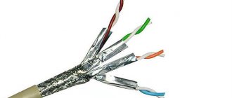
Crimping RJ-45 connectors of computer cables
Polymer RJ-45 connectors provide quick connection of cables to computers or connection of additional equipment to them. The cable in this case is a twisted pair, where the insulated cores are intertwined with each other.
Network cable crimping pliers
For twisted pair cables, crimpers with special matrices are used. Crimping is carried out in several stages:
- the wire is cleared from the outer sheath to a length equal to the depth of the plastic connector;
- twisted pair is divided into individual wires and grouped by color in a certain position (see below for additional information);
- the wiring is inserted into a special opening of the pliers and the ends of the wires are stripped of insulation;
- the plastic connector is covered with a crimper;
- a group of cores is inserted into the RJ-45 housing until it stops;
- squeezing the plastic with pliers and pressing the wires into the connector.
Polymer RJ-45 lug
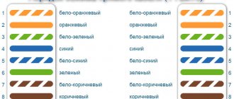
The wires of the network cable are grouped from left to right before entering the connector:
- white-orange;
- orange;
- green-white;
- blue;
- blue-white;
- green;
- white-brown;
- brown.
Problem
One of the most common reasons for the loss of Internet at home is a cable problem. There are many options:
- A wire has frayed somewhere in the corner connections - it happens that someone shuffled it or kicked it.
- The connection in the connector is broken - the wire there is open, so it may break. Sometimes the connection just drops. And over time, the crimp “dries out,” so you still have to improve the connection.
The bottom line is that when replacing a wire or repairing a connector, you still have to somehow reattach those same connectors. But this procedure is called crimping. And you can do this completely at home yourself (I’m telling you as a seasoned admin, and it wasn’t in times like these that you were cutting the cable). But you need a little theory - this is not electrical wiring. So first, a little theory, and then let's move on to practice.
Examination
There are also options to check the cable connection. The key is to get both ends. In practice, this does not always work out at home - after all, the provider will not give you his end of the line. Therefore, it’s easier to check on the device - if everything works, then it’s great. No - we are looking for a different reason.
LAN testers are used professionally. This device shows for sure which vein has a signal and which does not:
Additionally, you can use a multimeter, but here you will have to ring each wire separately. But what can you do, because Russian people can do everything)
Thank you all for your attention! If you still have questions, write in the comments. We press, we press and we will press)
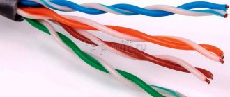
twisted pair
In the last section, we found out that twisted pair is a wire used for network connections in computer technology. Especially used at home to connect to the Internet.
It got its name from the building. Inside there are copper wires in a sheath, twisted in pairs. Twisting is done with a certain step depending on the number of such pairs. The whole point of such twisting is mutual cancellation of interference to improve the quality of the signal in the working network (after all, this wire also carries electricity, although not 220V, and reliability here is needed at a high level, but this is a topic for standards).
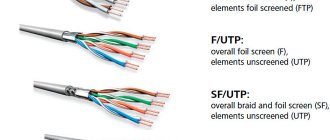
There are several types of twisted pair... Even many. The main classification is by device, not the main one - by protection. When installing at home, you will usually be dealing with a category 5 cable (if you want, look for it yourself, that’s not what the article is about).
In terms of protection, there is also nothing difficult - there is with protection, there is without protection. Protection does not mean from falling stools, but from the same interference that creates interference. This is usually not required at home, but you never know what you can get your hands on. The section is larger for the fact that you will have to open the cable during crimping, and you need to be prepared for anything) So a little anatomy for the system administrator and the home enthusiast to surf VKontakte.
So, there are pairs of wires inside - usually 2 or 4. The wire can be protected - we are talking about foil or braid. In this case, protection can be either for the whole wire or separately for each pair. There are a lot of subtleties, it’s better to open it right away and look locally. In home cable there is usually nothing like this - one braid, and there are pairs in it at once.
Twisted pair markings:
- UTP – regular, without protection, for home. If you need to restore a piece of your house and go to the store, just look for something like UTP5 - it will do just fine.
- FTP - with foil, also sometimes used indoors.
- SFTP – metal braid, used outdoors.
- STP – protection on each pair. When the wire is on the street near power lines (I hope you didn’t get caught there).
In total, the different options are arranged in the following figure:
An additional bonus is that there are multi-core and single-core cables. Stranded ones are used at home - the wire comes out flexible, just for active movements. It is better to use a single-core wire for industrial installation - up to the socket, the wire does not bend, but the signal transmission is much better.
I don’t even want to mention flammable and non-flammable, round and flat here - after all, this is not a system administrator’s textbook, but simply helping those in need at home. So if you have questions, run to the comments.
Connector
The connector is an Ethernet plug. It is usually designated RJ-45. Most connectors are similar to each other. The transparent base allows you to visually control the crimp. After connecting the connector to the Internet cable, the top latch secures the plug as it is inserted into the port.
On the back of the connector there is a place for inserting the wire. A little higher there is a bar that helps securely fix the cable. There are eight channels inside the Ethernet plug.
Their width corresponds to the diameter of the cores. Eight contacts are located nearby, which are initially in a raised position, so the cores easily fit into the sockets.
During installation, the contacts are lowered and pressed into the cores. If you do not recess the contacts completely, connecting the plug to the input will be problematic. There are connectors that provide a system for correctly inserting the wire into the required positions.
Wire selection and standards
In the last section I mentioned the categories of twisted pair, here we will consider this point in a little more detail. After all, the anatomy and transmission speed on the cord also depend on the category.
I recommended that you take category 5, but category 6 (CAT5, CAT6) is also suitable. All options are shown in the following table:
It will be important to choose a cable for the required speed. And this also depends on the number of wires inside. It usually happens like this:
- 2 pairs (4 wires) – up to 100 Mbps
- 4 pairs (8 wires) – from 100 Mbit/s
Typically, ISP technology limits you to 100 Mbps internet speed. But soon this threshold will be passed. What do I mean - usually there will be exactly 2 pairs on the Internet cable, but on home cables (from the router to the computer) there are already 4 pairs.
4 pairs, or 8 wires
How to connect a connector to an Internet cable: order of wires
A provider cable is used to connect client devices to the Internet. When concluding an agreement with a service provider, specialists perform the installation themselves and the user only has to insert the plug into the device port. However, there are times when an apartment requires additional wires to connect legal entities. Therefore, it is worth figuring out how to connect the connector to the Internet cable.
Crimping theory
And now we are approaching the crimping procedure. But there is still something to clarify, the final frontier.
You have all seen the connector at the end of a twisted pair cable, which also goes into the network connector of a network card or router. This plug has a special marking. The one that is mainly used now in the home local network is RG-45. A little about the connector design and connection.
- The twisted pair is installed in the connector socket.
- The twisted pair wires are routed through special grooves in the connector.
- The contact mechanism of the connector is knives. In store condition, they are separated, providing a path for the cable wires.
- When crimping, apply pressure to the knives, and they cut through the sheath and ensure tight contact with the wire cores.
- On the other hand, the contacts of the knives remain open - they provide a connection to the network adapter when connected.
Here is a picture of how the knives work:
And here is the connector in an enlarged view (the same wire tip or “jack”):
This connection is reliable and transmits the signal perfectly. But beginners may not be able to do enough at first - and either there will be no connection, or it will be established at a low speed (this is one of the reasons for the decrease in speed on the network). The best way to fix it is to squeeze it harder again, or re-press it again. In practice, at our university this procedure did not work out for everyone the first time - so everyone starts somewhere.
Does Wi-Fi cause cancer?
According to our statistics, only 7% of users know the correct answer to this question YES NO Reply
How to check the patch cord
So, you have crimped your first patch cord and now you need to check it. In general, there is a special device for these purposes - a LAN tester. It consists of a transmitter and a receiver.
We plug one side of the cable into the transmitter, and the other into the receiver and watch. The tester checks each core in turn. If everything is normal, then the indicator next to her number lights up. If there is a break somewhere along the vein, the indicator does not light up.
All this is good, but in fact, rarely does anyone buy a LAN tester, especially when the need to crimp an Internet cable arises once every few years. In this case, there is an easier way. For this we need a switch (switch) or router. We disconnect all wires from it, after which we plug in the patch cord being tested into any LAN ports. It looks like this:
If the LAN indicators light up, the patch cord is working. If not, it means it is damaged somewhere. Attention! You cannot carry out such a test if the switch or router is connected to the local network or the provider's network via the WAN port, since you are actually making a loop, which can lead to problems on the network. But if nothing but a patch cord is connected to the device, then there will be no harm from this.
The entry was published on February 29, 2022 by XasaH in the General Questions category and tagged rj45, twisted pair, crimping, pinout.
Tools
The main thing when crimping is to make a high-quality cut with knives on the shell. And for this you need to create the right strong pressure on the contacts. Well, we couldn’t do it without creating tools, although we can do without them.
Pros use a special tool - crimping pliers, or crimper. I’ve also seen names like “wire crimpers” or “connector crimpers.” Here, who already has what taste, you will probably hear some other versions.
This thing isn't that expensive. You can find a working copy for less than 1000 rubles. For a one-time repair at home, the thing is useless. But their main feature is their functionality tailored for twisted pair cables:
- Cut the braid exactly to the level of the wires
- Stripping wire insulation down to the core
- Simultaneous crimping of all knives with the required force
- Sometimes there is a socket for crimping and telephone cable (RG-11)
This is what they look like:
Connecting a peripheral device
Advanced PC users need to know how to correctly pinout the RZh-45 connector for USB. This network structure is especially relevant in those industries where it is necessary to connect expensive server systems, as well as office equipment and cash registers. For such manipulations, it is better to prepare a regular soldering iron, but if it is not available, then you can get by with twists.
When the cable is completely crimped, the technician must strip the cut end by at least 5 cm. Next, any USB plug is carefully disassembled so that the connectors are ultimately freely accessible. It is worth noting that the black and red cables should be stripped down to the copper base, and after that they should be twisted together. If the RJ-45 and USB twisted pair is ready, then you need to perform the following steps sequentially:
- Solder the white-green wire from the third connector to the red-black twist.
- The green cable from the USB device is carefully connected to the blue wire from the fourth connector.
- All that remains is to twist the white-blue core from the fifth connector with the white cable.
The experts themselves claim that using a twisted pair cable with an RJ-45 connector is not difficult even for a beginner. Don't worry that the crimping may not be as good as in the store. The communication channel will not be lost and no short circuit will occur. Using unprofessional tools can only create slight interference on the line, which will not be noticeable on a cable up to 5 meters long. If the master is not confident in the quality of his work, then it is better to redo everything so that the network does not fail at the most crucial moment.
No tool
In my life I have seen many crimping methods. But the most interesting of them was teeth, because... a person’s mother-in-law was a dentist... So sometimes you don’t even need a tool at all.
Another handy tool that everyone has is a screwdriver. Moreover, this is perhaps the most popular tool at home. The main thing is not to break anything and push through the contacts efficiently. If the connection is not established during the test, you just need to try again. The working method is difficult, everything constantly slides off - but without fish there is fish.
Another home helper is pliers. But my advice is that it’s better to suffer with a screwdriver. The pliers do not provide strong indentation (especially in the middle), and with great Russian heroic prowess they easily break the connector into small pieces.
Friends! Especially for lovers of something interesting and secret, we have our own closed club “Atlantis”.
- Daily up-to-date earnings schemes.
- Breakdown by level - at level 1 there is a bare public, at level 4 - a highly profitable private.
- For free. You just need to be on time. Only 3000 places for level 1.
Be sure to register, otherwise only 5 guest articles will be visible - LET'S GO.
Crimping diagram - pinout
And now the science itself. It’s one thing to apply pressure, another thing is to correctly insert the wires into the cores (and this is the most important thing in order to correctly crimp a twisted pair), and into both connectors - a random set will not work here. The order is very important. In total, the connector has 8 grooves for 8 cores. If 4-core wires are crimped, some of the grooves are left empty, the main thing is to get it right.
First, let's look at the classic crimping of an 8-core wire. There are 2 ways:
- Direct cable crimping (type B, 568B) is used in 99% of cases. Used to connect peripheral devices to a router/hub/switch.
- Cross crimp (crossover, type A, 568A) - used for direct computer-to-computer connections.
For reference . Now modern adapters understand both of these methods, but the first option of direct crimping remains preferable.
The names of twisted pair crimping circuits are taken from the way the wires are arranged in relation to each other. Look at the images below and you will understand everything. The main thing here is a view of the connectors from below (where there is no leg).
Direct crimp
Use this pinout diagram!
If the pictures are suddenly unavailable for some reason, the arrangement by color is:
1. White-orange 2. Orange 3. White-green 4. Blue 5. White-blue 6. Green 7. White-brown 8. Brown
Cross circuit
Four wires
Another option for 4 cores is the case when there are only 2 pairs. This is how they usually do it:
The whole point of proper pinout is to match the wires on both sides of the cable, without even knowing how the connector on the other side was crimped. An unspoken standard where you don’t have to run to the provider’s shield. The numbers 1-8 in the pictures are sometimes squeezed out on the sockets, this is for those who do not want to confuse the order.
Installation if there is no crimper
You can repair an old cable or connect a new one to a connector without the help of a special tool. Some people use a simple screwdriver. The insulation is removed with a regular knife.
When using a knife, everything must be done very carefully. Otherwise, the wires may be damaged. Side cutters can be used to trim contacts.
The wire is installed in the plug and secured with a bar. This will prevent the cable from accidentally falling out. The connector is installed on a flat plane, after which the contacts are pressed into the cores. Finally, you need to make sure that the plates are at the same level.
Crimping procedure
Now let's move on to the correct way to crimp the cable. Be careful when working - the main thing is not to damage yourself, and the connectors are cheap)
Step 1. Remove the insulation
First, remove the insulation from the wire - you can carefully pry it off with scissors or use a stripper on a crimper - insert it, turn it, and the wrapper comes off. It is fragile and can be removed quite easily. You don't need to remove much insulation - a couple of centimeters from the end is enough. If anything happens, you can trim everything later. The pliers have special marks indicating at what level the coating should be cut.
Step 2. Straighten the wires
Now we take our wires, straighten them and arrange them according to the pinout diagram. From the recommendations - try straightening them with a pencil or hand - they become smooth and closely spaced to each other - which is what we need.
Step 3. Trim
Now is the time to cut and straighten our wires. We cut it either with wire cutters, or with the same pliers, or even with a knife. Leave about a centimeter of clean wire. With practice, you will learn to accurately check the distance.
Step 4. Getting into the connector
The hardest part. Now we need to insert our design into the connector. When inserted, the connector is positioned with the leg down. Why is it difficult - the wires try not to fall into their grooves, they crawl into neighbors, bend, and get tangled. Here the recommendation - patience and once again paying attention to the pencil treatment - helps.
Step 5. Insert all the way
After the hit, we press on the cable so that the wires go all the way. In this case, the wrapper will be hidden in the connector itself. If the wrapper does not fit into the connector, fractures are possible in the future. If the opposite turns out to be short, the wires will not reach the knives. So everything is done with experience and by eye.
Step 6. Crimping
Now is the time to tighten our knives - the methods were discussed above, but it is better to use pliers. Take it and live it.
Step 7. Check and refinement
Be sure to check the connection on your computer or router before putting away your tools. Sometimes it may not work out the first time. The easiest way to correct the situation before getting upset is to squeeze the knives again, but harder. It helps a lot.
If there is no connection, pay attention to this:
- Are the wires routed exactly according to the diagram? Didn't they fly out? Look through the connector.
- Have the wires reached the stop of the connector? Were the knives able to reach them?
The rest can only be attributed to cable failure.
Initially, before crimping the network cable, you can install these casings. They perfectly protect against bending near the connector, but in practice everything works without them. There are a lot of species, that’s not what the article is about. For reference.
Wiring diagram or connection of electrical cables in a junction box
Cables and wires in residential and non-residential buildings are laid from a switchboard with an electricity consumption meter, safety plugs or circuit breakers under the floor, along the walls to distribution boxes, where they are connected by twisting or using terminal blocks (electrical clamps).
From the distribution boxes, electrical wiring is laid to other junction boxes or switch boxes, which are connected to one machine or the same group and to switches, sockets, and lamps. It is possible to make a connection without special education or experience as an electrician; just follow these instructions.
Usually 3–4 groups come to the apartment (including a separate group that comes to the electric stove, which is laid with independent cables or wires). Thus, if there is a fault on the line, only part of the building or apartment is disconnected from the power supply. Pay special attention to the proportional and uniform distribution of the load between the circuit breakers or safety plugs in the electrical panel.
Before starting work, it is necessary to de-energize the line on which work will be performed by unscrewing the plugs or turning off the machine.
As a rule, one distribution box is installed for each room; if the sockets are significantly distant, an additional one can be installed, specifically for the sockets.
Step-by-step guide to installing a junction box
- Insert cables or wires into the box through seals in the holes (for overhead boxes) or through pre-drilled holes in boxes installed inside the wall.
- Fix the box to the ceiling or wall using 2 self-tapping screws or dowels for an overhead installation method, or seal it flush with the wall or ceiling for a hidden installation.
- Carefully remove the outer insulation of the cable right up to the entrance to the junction box. At the same time, it is necessary to maintain the integrity of the internal insulation of the cores. It is good to isolate accidentally damaged areas with electrical tape.
- Adjust the length of the wires or cores, leaving a maximum margin, while taking into account the possibility of laying them inside after completion of the work. Usually a margin of about 15 cm is left. If there are a large number of wires in one junction box, they are shortened to 12–10 cm.
- Strip the ends of the wires or cable cores.
- Connect the cores (wires) according to the operating diagram using terminal blocks (electrical clamps), insulating PPE caps or twisting.
- Insulate the twisted ends with electrical tape or screw on insulating caps.
- Separate the bundles of phase, neutral, and grounding wires to the sides, then carefully lay the wires inside; to make the task easier, you can carefully push them in using the wooden handle of some tool.
- Close and screw the lid.
Learn more about choosing a connection method and features of video editing
Distribution box wiring diagram
All protective or grounding (marked as PE in the diagram, highlighted in yellow) and neutral conductors (marked N in the figure, marked in blue) are connected to each other by color, as shown in the diagram. There will be no ground conductor if the wiring is two-wire.
Phase conductors (highlighted in black and red) are a little more difficult to disconnect; if the wiring from the distribution box goes only to the sockets, then the phases are also connected to each other.
In the case when the wiring goes to a lamp with a single-key switch (as shown in the figure), the wire that comes from the switch is connected to the phase going to the lamp (in the picture L to lighting), and the phase coming to the switch is connected to all phase wires (on the diagram L for the switch). There should be 4 connections.
When distributing conductors to a luminaire with a two-key switch, a four-core cable is laid before it (2 on-phase conductors, 1 off-phase, 1 neutral, 1 “ground”). In the case of two-wire wiring, it is three-wire, since there is no ground conductor. The phase conductors going to the sockets are connected to each other. The phases of the power cable coming to the common terminal of the two-key switch are also connected, 2 wires from which go to the lamp lamps separately. Below are wiring diagrams for a two-key switch without ground.
All neutral and grounding conductors (if the latter are present) are connected together. There should be 5 connections inside the box (including the connection of the grounding conductors). Below is a wiring diagram for a two-key switch with ground.
Attention! Before applying voltage, carefully check the connections again. To avoid short circuits, all connections must be made strictly according to the diagram, the insulation must be undamaged, and the twisting points must be reliably insulated or protected with insulating caps.
bouw.ru