A circuit breaker is a convenient and practical replacement for fuses, which not only has higher tripping accuracy, but can also be used a large number of times. How to properly connect a machine is a question that not only novice electricians, but also every self-respecting owner of a private house or apartment should understand. And this article will not only tell you how to install an automatic or differential switch, but will also introduce readers to the variety of switching equipment and the operating principle of package switches.
Design of a standard circuit breaker
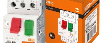
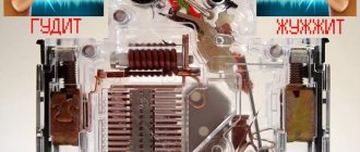
For example, we will use the BA47-29 series switch as the most popular switching device with an affordable pricing policy. Before you learn how to properly connect a circuit breaker to a single-phase network, you need to consider its design.
The BA47-29 series circuit breaker consists of the following elements:
- A copper terminal connected to a fixed power contact. Most often, the supply wire is installed exactly in this place.
- The movable contact, which makes the switching, and the copper stranded conductor, has a sufficiently large cross-section.
- Arc chamber.
- A special thin plate with a hole through which gases formed after the arc escape.
- An electromagnetic release, presented in the form of a simple coil. The stranded conductor from the moving contact is soldered to the coil.
- Plastic, fully dielectric handle.
- A bimetallic plate that acts as a thermal release. The plate is located immediately behind the reel.
- A special screw for adjusting the bimetallic plate. The screw is not installed on all models, and adjustment is made at the manufacturer.
- The lower copper terminal, from which the conductor goes directly to the consumer.
A three-phase machine has a similar design, but instead of one terminal, it uses three, isolated from each other.
Enter from above or below
A very important question that worries both many electricians and just home craftsmen: how to connect the machine, from above or from below? To answer this, you will have to refer to the regulatory documentation, namely, the Rules for the Construction of Electrical Installations.
Paragraph 3.1.6 states that the machine should be connected to the electrical network from the side of the device on which the fixed contact is located. This means that the voltage in a single-phase or three-phase network must be on the side of the switch that does not break the electrical circuit. Paragraph 3.1.6 applies to many types of switching equipment. This can be not only a single-contact, but also a two-pole or three-phase circuit breaker, as well as a differential package or RCD.
You can find out the location of this contact only by disassembling the bag, which is not very convenient every time you replace it in the apartment. But the design of all machines is almost the same, so you should find out where the fixed contact is located on only one switch. And it is located on top, so the connection of a single-pole or two-pole circuit breaker must also be done from above.
If you happen to have a packet from an unknown manufacturer in your hands, then just look at its body, or more precisely, the front panel. In this place, most often all the necessary information is placed on the machine, such as the model, accuracy class, and connection diagram of the circuit breaker with the exact location of the moving and fixed contacts.
Conclusion: the connection of the circuit breaker to the electrical network must be done from above. This is what the regulations say, which help avoid unnecessary confusion. But if you look from the technical side: is the difference in connecting the power cable significant? Answer: no, it does not matter at all from which side the operating voltage is supplied to the package. The device will work properly both with connections from above and from below.
The sequence of correct connection of the machine
Before you learn how to install the machine correctly, you need to stock up on the most necessary tools. If in the future electrical installation turns into the main type of income, then the following list of tools will not be enough.
- Phillips and flat head screwdriver. Preferably dielectric.
- Indicator screwdriver.
- Monter's knife.
- Screwdriver.
Professional craftsmen also have crimping pliers in their bins, and instead of a fitter's knife, they most often use a special knife for stripping insulation. This is not only more convenient, but also allows you to get the job done faster.
Step #1: DIN Rail Mounting
Do-it-yourself installation of a DIN rail in a panel takes 10-15 minutes. The main condition for fast work is the presence of a good screwdriver, preferably with an autonomous battery.
There are three main types of DIN rails:
- Ω-type. Products of this form are considered the most common, and any circuit diagram for connecting machines in a panel implies the presence of such a product.
- C-type. The ends of the product are bent inward.
- G-type. This rail is similar to the C-shape, but with only one shorter side.
The sequence of installing a DIN rail in an electrical panel:
- Mark the location of the DIN rail in the panel.
- Place the DIN rails on the metal surface and secure them on one side using tex, a special self-tapping screw.
- Align the rail using a building level and secure it on the other side.
If necessary, the DIN rail can be cut to any length, but this product is mainly sold in 2-meter lengths.
Step No. 2: installing the machine on a DIN rail
The simplest procedure in the entire topic “How to connect a machine in a panel.” On each circuit breaker, on one side (usually the bottom) there is a special plastic latch. It must be removed, installed on the DIN rail and pressed until it clicks. After this, the circuit breaker will be securely fixed and you can proceed to connecting it.
Step No. 3: connecting the machine to the network
To find out how to correctly connect the machine in the electrical panel, you must first read the paragraph, which discusses in detail the question of whether the package should be connected from below or from above. As the regulatory documents say, voltage must be applied to the fixed contact of the switching device, and most often this contact is located on top.
Before connecting a single-pole or double-pole circuit breaker to the network, it is necessary to remove the insulation from the wire, crimp it together with the tip and make sure, using an indicator screwdriver, that there is no voltage coming to the packet.
After this, insert the securely pressed tip into the standard connection point of the machine and clamp the connection point using a bolt specially provided by the manufacturers. Check the quality of the connection by moving the wire without applying unnecessary force. If the installation is done correctly, then the machine can be turned on and checked whether everything is working in the apartment.
Location of the electrical panel in the room
It is important to decide on the installation location of the shield. Its location requires constant access; the switchboard door must not be blocked by foreign objects.
In most cases, the shield is mounted near the entrance to the house, or already inside, but immediately in the corridor of the house or apartment. This simplifies the installation of the cable supplying voltage to the room.
- The height of the shield is determined at the eye level of the residents of the home. This arrangement is necessary for the convenience of taking meter readings when paying for electricity.
- Previously, in not-so-distant times, meters with automatic machines were installed on a wooden plank on the wall.
- Although their location was usually under the ceiling, it is undesirable to do so. In the shield, the entire structure will be in a safer position.
Modern electrical panels have high protection classes, a good solid base, and a lock with a key. What is an obstacle for small household members to enter there.
In a private house, when placing the panel, the location of the high-voltage line from where the cable will be supplied to the room is taken into account.
Common mistakes when connecting the machine to the network
Unfortunately, even experienced electricians with many years of experience behind them make minor mistakes at first glance, which can later lead to very big problems. To avoid such errors when connecting the input machine, you need to familiarize yourself with them in advance. Prevent a problem before it occurs.
Wire clamp with insulation
A very popular mistake that is made mainly due to inattention. The main difficulty is that a visual inspection may not show any results: all the machines in the electrical panel are intact, the wires are not damaged, and there is still no light in the apartment.
And the problem is the incorrect connection of the power cable, or rather, too small a section of the removed insulation. The technician removes a small piece of insulation from the wire, places it in a fixed contact and tightens the bolt. The standard connection of the machines is in the panel and everything is done according to the rules. But only the contact could get not to the conductive core itself, but to the insulation. Result: poor contact, which will lead either to a burnt-out machine or to a lack of light in the apartment. It may take a long time to determine the problem and reconnect the cable to the packager.
Therefore, in order to avoid such consequences, the connection of a single-pole or two-pole machine must be made with a high-quality stripped wire. And it’s okay if the cleaned core peeks out a little from the insertion point.
Connecting several wires of different sections to the machine
Before installing circuit breakers, you need to know how to do it correctly. And often in apartment panels you can see several wires that are installed in one regular place for connection. And it’s good if it’s 2 wires, but many craftsmen try to connect 3 or more wires of different sections to the machine. After which the life of the circuit breaker is reduced several times.
If the wires to the machine have different cross-sections, then when the contact is tightened, the one with the larger cross-section will be well secured. A cable with a smaller diameter will “walk” freely in the package’s seat. The result will be poor contact, which will soon lead to complete burnout of the connection point of the machine.
Therefore, it is best to connect the machines to each other with a single piece of wire, stripped only in places of direct contact with the circuit breaker. This piece of wire is also called a comb bus, which you can make yourself.
Connecting several machines to a meter or to each other can also be done using special crimp terminals NSHVI-2. These are consumable products into which 2 wires can be pulled at once. The only downside to this installation option is the need to purchase special crimping pliers.
Incorrect formation of core ends
How to connect circuit breakers in a panel is already known and the main errors have been discussed, but even such a minor error as incorrect formation of the end of the conductor can lead to the need to replace the switch.
The sequence of connecting cables to machines is standard: strip the core to the required length, guide the wire into the seat and tighten the lock, which is most often made for a Phillips screwdriver. They try to make the end of the conductor straight. But in order to improve contact at the junction of the wire and the copper plate of the machine, a U-shaped bend must be made at the end of the cable.
This is the most reliable advice on the question of how to properly connect machines to the input power supply or apartment wiring. The U-shaped bend allows you to increase the area of contact between the wire and the copper plate of the bag, and, accordingly, improve the quality of contact. The rest of the work will be done by the ribbed surface of the slots for connecting the machines.
Connecting a stranded wire to a machine without special ends
How to connect a circuit breaker, single-phase or two-phase, using a stranded cable? Answer: only using special crimp lugs such as NShV or NShVI.
Many electricians do not bother themselves with high matters and make this connection in two standard ways:
- Tin the end of the copper wire.
- Without using any contact materials at all, simply squeezing the wire with pliers.
Both the first and second methods are incorrect, and will soon only lead to the replacement of the machine. And if everything is clear with the second point, then cable soldering, on the contrary, is encouraged by all technical and regulatory documentation. Unfortunately, not always. Even a high-quality tinned wire under voltage gradually begins to “drain”, and in order to prevent contact deterioration, it should be constantly checked and tightened. Therefore, soldering is not practical in this case.
It is best to purchase special crimping pliers and tips NShV or NShVI. All that remains is to strip the input cable, put a tip on it and crimp it using pliers. After this, the carefully crimped stranded core can be secured in the machine and there is no need to check the quality of the connection every few months.
With press jaws, installing automatic machines will become a quick, and most importantly, high-quality procedure. This tool is especially useful when the electrician profession is a constant source of income.
Is insulation coming into contact an error?
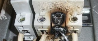
The most common mistake when installing a machine in an electrical panel is the presence of insulation that has gotten under the contact mount. It often happens that when installing circuit breakers or changing the box, after a while, the wiring inside it burns out. This happens when the ends of the wires are poorly stripped and particles of insulation get under the clamp, thereby worsening the tightness of the connection. In this regard, the insulating layer of the electrical wiring and insulation of the machine melts, which can cause a fire.
To avoid making such mistakes, it is necessary to thoroughly clean the ends of the wires connected to the automatic protection, and then make sure that there are no insulating particles left on the cleaned ends. After cleaning the insulation, form connections, tightening them well with a screw clamp.
How to properly connect SIP to a machine
SIP is a self-supporting insulated wire that is used almost everywhere to introduce electricity into the house. Therefore, the question of how to connect a SIP to a single-pole circuit breaker is very relevant.
Firstly, the SIP is made of aluminum, and the contact plate of the circuit breaker is made of copper. The correct connection of copper and aluminum requires the use of a special crimp sleeve, and in the case of subsequent connection to the machine, a sleeved tip, at the point of contact of which there is a special copper coating. It is impossible to connect a SIP to a machine without such a tip, since aluminum tends to oxidize, causing the quality of the contact to be lost. And poor contact is the first cause of fire.
The sequence of connecting the SIP to the machine:
- Strip the cable.
- Place a sleeved tip on the open core. It is important to put it on tightly and so that the insulation begins immediately behind the sleeve.
- Using a hydraulic press, compress the sleeve in two places.
- Place a heat-shrink tube over the open part of the sleeve and heat it with a hair dryer.
- Insert the tip into the machine and tighten the contact properly.
This installation method is the same for both single-phase and three-phase machines; you just need more tips.
Which is correct: machine before or after the counter
To answer this question, you should also refer to the PUE, namely to paragraph 1.5.36, which states that for the safe installation and replacement of meters in networks up to 380 V, a circuit breaker must be installed in front of them (at a distance of no more than 10 m) . And this same machine in front of the meter acts as a switching device to disconnect the entire apartment or house, and its nominal values must be appropriate.
The number of machines after the meter is determined directly by the owner of the apartment or house, or by the design organization performing the installation of electrical wiring. There are such electrical panels, the number of devices in which reaches 40-50 pieces, and this is without RCDs and differential circuit breakers. When installing an introductory machine before the meter, the same one can be installed after it. This will not affect the operation of the metering device in any way.
Important! Only representatives of energy supervision authorities can connect the electric meter to the network. Therefore, before connecting an apartment, you should find such an organization in your city and formally call a specialist.
How to install an RCD: before or after the machine
The residual current device is a very useful switching device that requires correct installation, otherwise its operation may be unstable. If the installation is carried out incorrectly, then at the first short circuit in the apartment you will need to replace the RCD, which is an order of magnitude higher in cost than any circuit breaker.
There is no particular difference whether the RCD will be located before or after the machine. But the issue can be considered from a practical perspective. Any residual current device does not have protection against short circuit currents, and if you install it without a circuit breaker, the consequences can be very different, including damage to the device.
Therefore, it is best to install an RCD immediately after the introductory machine, but before the packetizer, the line from which will go directly to the consumer. This will provide reliable protection of the circuit from short circuits, and users from the unwanted action of operating potential when a phase wire gets into contact with the housing of a household appliance.
How to properly connect a differential machine
Of all types of switching devices, a differential automatic machine is considered the most practical, but at the same time expensive. It combines the functions of a circuit breaker and a residual current device. Such a device is not installed like a regular package, but requires a slightly different approach.
The differential machine is connected as follows:
- The neutral wire is installed in the upper clamping contact.
- A phase wire is installed in the right clamping contact.
It should be immediately clarified that the contact locations can be changed, but the manufacturer marks the connection sockets with the appropriate letters. And under the operating or non-working position switch there should be a special button to check the functionality of the device.
The neutral wire that passes through the differential circuit breaker cannot be connected to other circuit breakers. With this installation, the device will constantly turn off, since the currents flowing through the conductor are completely different.
There are schemes in which a differential machine is connected to a group of packagers, while in other schemes such devices are used exclusively for one consumer. When designing wiring, it is better to choose the second option, in which, when the device is triggered, only one consumer will be de-energized, and not a whole group of machines.
Selection of RCD according to main parameters
All technical nuances associated with the choice of RCDs are known only to professional installers. For this reason, specialists must select devices when developing a project.
Criterion #1. The nuances of selecting a device
When choosing a device, the main criterion is the rated current passing through it in long-term operating modes.
Based on a stable parameter - current leakage, there are two main classes of RCDs: “A” and “AC”. Devices of the latter category are more reliable
The value of In is in the range of 6-125 A. Differential current IΔn is the second most important characteristic. This is a fixed value, upon reaching which the RCD is triggered. When choosing it from the range: 10, 30, 100, 300, 500 mA, 1 A, safety requirements take priority.
Affects the choice and purpose of installation. To ensure the safe operation of one device, they are guided by the rated current value with a small margin. If protection is needed for the house as a whole or for an apartment, all loads are summed up.
Criterion #2. Existing types of RCDs
RCDs should also be distinguished by type. There are only two of them - electromechanical and electronic. The main working unit of the first is a magnetic circuit with a winding. Its action is to compare the values of the current going into the network and returning back.
There is such a function in the second type of device, but it is performed by an electronic board. It only works when there is voltage. Because of this, the electromechanical device protects better.
The electromechanical type device has a differential transformer + relay, and the electronic type RCD has an electronic board. This is the difference between them
In a situation where a consumer accidentally touches a phase wire and the board turns out to be de-energized, if an electronic RCD is installed, the person will come under voltage. In this case, the protective device will not work, but the electromechanical device will remain operational under such conditions.
The subtleties of choosing an RCD are described in this material.
Connecting two-pole and three-pole circuit breakers
The principle of connecting two-pole and three-pole circuit breakers is exactly the same as in the case of a single-phase packet switch. And if the question arises of how to connect a three-phase machine, then you should perform all the operations that were carried out with a device designed for a single-phase network.
In the same way, strip the wires, crimp them using lugs and a press, and install each wire on the corresponding fixed terminal, and then clamp it with a screw clamp. If a three-pole circuit breaker is installed in a production facility where further connection of asynchronous or synchronous motors is planned, then after installation the phase rotation should be checked using a special device - a phase indicator. If the phases are reversed, the motor will begin to rotate in the opposite direction.
If you do not know how to connect a two-pole machine, then the principle of connecting it is the same as when installing an RCD. Standard places are provided for the connected phase and neutral wires.
It should be immediately clarified that the price for installing single-pole, two-pole and three-phase circuit breakers in Moscow varies. Therefore, it is necessary to take into account the types of switching equipment that will be installed in the panel in the future.
Drawing up an electrical panel diagram
An important step in installing an electrical panel is creating its diagram. There are several explanations for this. Let's say, if you plan to repair or modernize the wiring in your apartment in the future, using the diagram you can quickly establish what each machine and part in the panel is responsible for. You will also need the diagram when accepting work as an electrician. In addition, connecting wires with such a diagram on hand is much easier. You can either draw it manually or in specialized programs, and then print it.
The electrical circuit is created in several stages. The first step is to find out what kind of electrical system is in the house, then divide all points of electricity consumption into several categories. After this, based on the existing data, a shield diagram is created
It is extremely important that the diagram used symbols, which are described in detail in GOST 21.614 “Conventional graphic images of electrical equipment and wiring in the original”
So, as mentioned above, all work begins with determining the power supply and grounding system in the apartment, since the connection of the panel will depend on this. You can find out by looking at the sign on the floor or by going to the housing office. Often, three systems TN-C, TN-S, TN-C-S are installed in residential buildings.
It is worth immediately noting that the first system was created according to old GOST standards and was used in houses that were built before 1998. The TN-C system is represented by two-core copper or aluminum wiring. A three-phase cable (L) with one conductor PEN, in which ground and neutral were combined, went to the floor distribution board. The last two systems are used in modern homes. A three-core copper wire is laid in the apartment, and a cable with three phases (L), neutral (N) and PE ground (S) is connected to the switchboard.
Summing up
Key technical points to remember from this article:
- The supply wire is connected to the fixed contact of the circuit breaker. On almost every machine such a contact is located on the top.
- Only the phase passes through a single-pole circuit breaker, phase and zero pass through a two-pole circuit breaker, and 3 working phases pass through a three-phase circuit breaker. In the latter case, it is also necessary to use a phase indicator to determine the correct phase rotation.
- Phase and zero must pass through the RCD and differential circuit breaker.
- To connect wires to the circuit breaker, use special crimping lugs and press pliers. Especially when installing multi-wire cable.
- Before connecting the cable, it is necessary to remove sufficient length of insulation from the core. Otherwise, insulation will be the first cause of poor contact.
- The main circuit breaker is mounted before the electric meter in order to ensure the ability to quickly replace the electricity meter in the event of its failure.
Before any electrical installation, you should check the regulatory or technical documentation. Only then will all work with electrical devices and consumables be considered correct, and most importantly, legal.
Single pole
For a single-pole connection, it is necessary to have a negative and power conductor. This method was used previously and was a unified standard, where the phase conductor was connected to the input contact AB, then passed through the output contact, went to the electric meter and was routed through the RCD. The neutral conductor is also powered by connecting through the meter.
Sometimes it is allowed to install the AV on the neutral conductor, although this contradicts the rules specified in the PUE, which says that the releases are installed when, when triggered, all conductors related to this circuit will be de-energized. Many people install two machines, one for plus, the other for minus. Therefore, it is worth considering whether it is necessary to set the machines to zero when there is a threat of equipment failure according to the description of the PUE.