Electrical panels located on the landings of apartment buildings are under the control of electricians from the management company. However, you must agree that every home craftsman is obliged to know the purpose of electrical devices enclosed in a metal box.
We suggest you figure out how to install a circuit breaker if an urgent need arises. We will tell you how the machine works and provide recommendations for choosing an electromechanical device.
This knowledge will help you replace the device yourself and take action in an emergency when the machine has tripped.
Connection diagrams
So, the operating principle of the circuit breaker is now clear, you can proceed directly to its connection diagrams. Let's start with the fact that machines can be connected to single-phase and three-phase networks. What machines are needed for this? If the conversation is carried out from single-phase networks with a voltage of 220 volts, then either a single-pole device or a two-pole device is usually installed in them. The circuit itself will depend on whether it uses a ground loop or not.
If two wires enter the house (zero and phase), then a single-pole version can be installed in the distribution cabinet. In this case, the phase circuit will pass through the machine itself. If three wires enter the house (phase, neutral and ground), then the common circuit breaker must be two-pole. That is, a phase is connected to the first terminal of the device, and zero to the second. Grounding is routed to consumers (lights and sockets) through a separate terminal box. Next, the wires from the circuit breaker are routed to the meter, then to single-pole circuit breakers installed in groups, but as described in the first case. By the way, below is the system for connecting the machine.
As for the three-phase network, in this case it is best to install three-pole or four-pole structures. Everything here is exactly the same as in the case of a single-phase connection. That is, if the house uses wiring without grounding, then three phases of the power supply are connected to the fixed contacts. The neutral wire is routed as a separate circuit to consumers (sockets and lamps). If the house has a grounding system, then a four-pole model is installed, that is, three phases and zero will be connected to the device, and the grounding loop will go as a separate line to consumers.
Sometimes connecting a circuit breaker is associated with the correct implementation of some nuances of the entire process. Namely, by connecting wires to the device
What do you need to pay attention to?
Each model has its own requirements regarding the cross-section of the inserted wire and the length of the insulating sheath
This must be indicated in the product passport. Most often, the wire needs to be stripped to a length of 0.8 to 1.0 cm. It is important to understand that placing a wire with insulation in a clamp is unacceptable, because the diameter of the insulation is larger than the diameter of the core itself, so the contact between the clamp and the core will either be weak or completely absent. The wire is fixed in the machine with a screw, which is tightened with a screwdriver. After fixing, you need to check the quality of the clamp; to do this, the wire itself must be tugged slightly. If a stranded conductor is used to connect the machine, then it is best to put a tip on its end.
Selecting AV based on short circuit current
You can purchase AVs with short circuit ratings: 3,000, 4,500, 6,000, 10,000 Amperes. The choice of AV with the required rating depends on the length of the cable or overhead line from the transformer substation (TS) to your house, apartment or cottage.
If the transformer substation is located nearby, then the short-circuit currents are very high, so you need to purchase a circuit breaker with a cutoff of 10,000 A. In the private sector of households, there is a large length of overhead power lines, so you need to use a circuit breaker with a short-circuit current of 4,500 A. In other cases, the average value is - 6,000 A.
An electromagnetic release is a part inside the AB that, in the event of a short circuit (SC), opens the electrical circuit. Releases are divided into categories. We will look at the categories that are used most often:
B – the circuit opens when the rated current is exceeded by 3–5 times;
How to choose based on device characteristics and functions
The main parameter by which a circuit breaker is selected is the total current load from all connected electrical appliances
You also need to pay attention to other factors - network voltage, number of poles, housing security, wire cross-section, condition of electrical wiring
Determining the polarity of the machine
Depending on the type of electrical wiring, the pole of the machine is selected. For single-phase networks, single- and two-terminal devices are used; for three-phase electrical networks, devices with three and four poles are used.
Current selection
Current is the most important characteristic influencing the choice of machine. It is this indicator that determines whether the protection will work in an emergency. For electrical panels located near electrical substations, a 6 kA protective device should be purchased. In residential premises this value increases to 10 kA.
Operating or rated current
Operating currents are determined by the total load of all household appliances that the machine protects. The cross-section of electrical wires and their material should also be taken into account.
For the lighting group, 10 Amp circuit breakers are usually used. Sockets can be connected to 16 Amps. Heavy-duty appliances like electric stoves and water heaters require 32 amps at the circuit breaker.
The exact value is calculated as the total power of all household appliances divided by 220 V.
It is undesirable to greatly increase the operating current - the machine may not work in an accident.
Short circuit current
To select a circuit breaker based on short circuit current, you should use the rules of the PUE. It is prohibited to use switches with a breaking capacity lower than 6 kA. In homes, 6 and 10 kA devices are most often used.
Selectivity
This term refers to the disconnection in an emergency of only the problematic section of the electrical network, and not all the energy in the house. You should select machines for each group of devices separately. The input circuit breaker is selected for 40 A, then devices with a lower current are installed for each type of household device.
Number of poles
There are several types of machines: single-pole, two-pole, three-pole and four-pole. Single-terminal circuits are used in a single-phase network (one phase, two, three wires). The neutral is not protected in this case. Used for socket group or for lighting. A double pole switch is used for electrical wiring with one phase and two wires. Can be used as an input fuse for the entire network and to protect individual electrical appliances. Devices with two poles are the most common.
Replacing one two-terminal device with two single-terminal devices is prohibited by the rules of the Electrical Installation Code.
Three-terminal and four-terminal networks are used in a three-phase 380 Volt network. They are spilled by the presence of a neutral wire in a device with four poles.
Cable cross-section
The cross-section and material of the cables has a huge influence on the choice. Homes built before 2003 used aluminum wiring. It is weaker and needs replacement. It is impossible to install a new switch selected only by total power.
Copper cables carry higher currents than aluminum cables
Here it is important to take into account the cross-section - copper products with an area of 2.5 sq. mm. operate safely with currents up to 30 A
To determine the required value, use tables for calculating cable cross-section.
Manufacturer
You definitely need to pay attention to the manufacturer of the machine. It is better to purchase the device from a well-known, trusted company in a specialized store.
This will reduce the risk of buying a fake, and the purchased product will meet the stated criteria. Also, branded stores provide a guarantee on the switch.
Housing protection degree
Each switch has its own degree of housing protection. It is written as IP and 2 digits. Sometimes 2 Latin letters may be additionally used to describe auxiliary characteristics. The first number indicates the degree of protection from dust, the second – from moisture. The higher the number, the higher the security of the machine body.
Marking
The switch is marked with letters and numbers. It is deciphered as follows:
- letter A, B, C, etc. – class of the machine, means the instantaneous current limit;
- the number indicates the rated current at which the device operates in normal mode;
- A number in thousands of amperes is also indicated next to it, indicating the maximum current value at which the switch will respond.
The markings are indicated on the device body and in the relevant documentation.
Selection of machine
First you need to calculate the rated current value for your network. This can be done using the formula (Ohm's law):
I=P/U, where:
I - rated current in amperes "A".
P – power of all devices (sum of powers) in watts “W”.
U is the network voltage in volts “V” (mostly 220 V). You need to choose a machine with the nearest higher rated current value.
Also, the selection of a machine based on the value of the long-term permissible current should be made depending on the characteristics of the wiring cable. The rules for electrical installations contain calculation tables. The larger the cable cross-section, the higher the permissible continuous current.
To protect your home and equipment during voltage surges or network overloads, RCDs are simply necessary. For this purpose, an input two-pole circuit breaker of 25A, 32A or 50A is usually installed.
Description and principle of operation
Before discussing the principle of operation of the device, you need to find out why a two-pole differential circuit breaker is needed. If the voltage in the network increases or there is a short circuit, which can cause damage to some connected devices, the device turns off the power. In this case, both the phase wire and the neutral are disconnected.
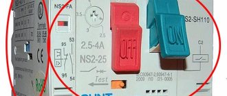
Photo - two-pole circuit breaker
This implementation is provided for by the PUE (Rules for Installing Electrical Equipment), which states that it is prohibited to disconnect the phase wire without disconnecting the neutral. This electrical machine is installed in a panel (located in the vestibule or directly in the apartment) to power individual devices to control their operation. If necessary, you can turn off the electric current yourself.
Photo - two-terminal device in the shield
An automatic two-pole switch consists of two single-pole circuit breakers, which are connected by a lever and have a common internal locking mechanism. When high voltage or surges occur, both devices are switched off at once, which protects the wiring from fire. Therefore, it is strictly forbidden to use two separate single-pole devices instead of one double-pole device. Since in this case only one of them will turn off, while the second will continue to power the apartment or house.
Purpose of machines:
- To protect networks of residential buildings and businesses from fire hazards;
- control of the operation of individual high-power electrical devices (machines, electric stoves, generators, boilers, etc.) installed in the country house, garage, industrial premises, etc.;
- disconnecting the load during voltage surges;
- branching (structuring) of electrical wiring.
Basically, two-pole circuit breakers are used in apartments with two-pole wiring (phase and zero), which is standard for all houses built before 1990. For this purpose, a single-phase two-wire cable is used, which has a phase and neutral conductor.
Photo - machine for an apartment
Despite the fact that both of these wires are considered equivalent, and theoretically they can be swapped, when wiring, it is customary to choose the neutral wire in blue (or install a heat-shrinkable tube of the appropriate shade at its end).
Video: using a two-pole circuit breaker in everyday life
How to choose a two-terminal network
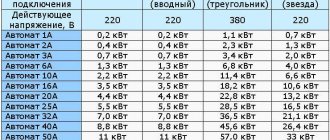
Before installing a two-pole input circuit breaker, you must select its rated current corresponding to the power of the connected equipment. Our table will help simplify the calculations, with the help of which you can easily find the required values in order to connect a two-pole IEC circuit breaker, TN-C, etc.:
| Rated current of a two-terminal network in a single-phase network, A | Power value, kW | Two-phase | Three-phase |
| 1 | 0.2 | 1.1 | 0.7 |
| 2 | 0.4 | 2.3 | 1.3 |
| 3 | 0.7 | 3.4 | 2 |
| 6 | 1.3 | 6.8 | 4 |
| 10 | 2.2 | 11.4 | 6.6 |
| 16 | 3.5 | 18.2 | 10.6 |
| 20 | 4.4 | 22.8 | 13.2 |
| 25 | 5.5 | 28.5 | 16.5 |
| 32 | 7.0 | 36.5 | 21.1 |
| 40 | 8.8 | 45.6 | 26.4 |
| 50 | 11 | 57 | 33 |
| 63 | 13.9 | 71.8 | 41.6 |
There is another simpler way to calculate the total power of a household network. For wiring in an apartment, this is easy to do. For example:
- 0.3 kW – refrigerator;
- 6 kW – electric stove and oven;
- 1.5 kW – other electrical appliances.
This turns out to be 7.8 kW. When choosing switches, you need to start from the nearest larger value. Suppose we have a two-phase electrical network, which means we settle on the indicator 45.6 according to the table. To protect the electrical system in your home, you will need a two-pole 40 Ampere circuit breaker.
Photo – legrand 63 ampere
Always pay attention to the designation on the machine; the rated operating current is indicated there. Check the quality certificate for compliance with operating parameters (thermal radiation, current, voltage).
How to install the machine
The RCD must be installed on a DIN rail. The connection of a two-pole dif circuit breaker is carried out in front of the circuit breakers. You need to install the DIN rail onto the panel body using self-tapping screws, then, using a special latch on the switch, secure it to the rail. When the circuit breaker is securely fixed, you can begin connecting the device to the electrical network.
If several machines will be installed on one rail, then their standard dimensions (modularity) must be taken into account.
Very often, after an old RCD or plugs, burnt wires remain that need to be cut off for convenient connection of the switch. If necessary, the wire can be extended, but changing is not recommended. We remind you that you must strictly follow the connection diagram.
Photo - connecting a two-pole switch
If you have an RCD with adjustment installed, then before turning it on and setting it up, you should check the correct connection. Even experienced electricians sometimes make mistakes and swap the neutral and phase wires. Installation is also possible directly on the shield, but it is much more convenient to work with a DIN rail.
It is necessary to install a two-pole differential circuit breaker in compliance with the rules for installing electrical equipment and safety precautions:
- In any circuits, electrical appliances must be installed by two electricians. In this case, one person carries out the installation, and the second ensures its safety;
- The connection diagram for a two-pole circuit breaker with independent input can be different, an example is provided in the drawing below; Photo - example of connecting an ouzo
- Replacement (installation of a new) RCD and other manipulations with electrical networks are carried out only after receiving special permission;
- To protect yourself from the danger of electric shock, you need to use special protective equipment (rubber gloves, dielectric mats, overhead protective grounding, etc.).
In this article, we will look in detail at the topic of how to connect an automatic switch off . Having at hand instructions with a detailed photo session and detailed comments, this task will be within the power of anyone and
the question of how to connect the circuit breaker will definitely be resolved.
The main function of a circuit breaker is to protect the electrical circuit of an apartment or house from a short circuit. It also performs a current limiting function. For example, let’s take a three-core wire with a cross-section of 2.5 mm, its long-term permissible current is 25 Amperes (see table 1.3.4 “Cable cross-section for long-term permissible current”), this is the current that the wire can withstand for a long time. Anything above 25 Amps will have a detrimental effect on it, it will heat up excessively, which will eventually cause the insulation to deteriorate and, as a result, a short circuit will occur. To prevent this from happening, the current is limited; to protect this wire, a machine with a rating of 25 Amperes is needed. A switch is automatically installed, as a rule, in the power panel, into which suitable wires supplying the house and outgoing wires come, these are the wires that diverge in different directions (rooms, floors) to lights and sockets.
There are circuit breakers of various designs:
- single-pole, used in a 220 volt network, only one phase wire is connected
- bipolar, used in a 220 volt network, two wires are connected, zero and phase
- three-pole, used in a 380 volt network, three phase wires are connected
- four-pole, used in a 380 volt network, three phase wires and one neutral are connected
As an example, we will consider a standard 220 volt household electrical circuit. For such circuits, both single-pole and double-pole circuit breakers can be used. It is optimal to use a two-pole circuit breaker because:
- two wires, phase and zero, are connected into it at once; if necessary, we break the circuit completely (this will be a significant advantage if, for example, overvoltage occurs, since when it appears, the phase turns out to be zero; by turning off the machine, we will save the equipment)
- The contact terminals of the circuit breaker have the most optimal screw clamp, the wire is well fixed over the entire contact area (most standard zero contacts have very poor clamping characteristics, the quality of their performance leaves much to be desired, if the phase is fixed well, and zero is bad, good from this for sure nothing will work)
- ease of installation of the machine (installed with one click on the DIN rail)
- the wires are easy to connect and disconnect if necessary (you just need to unscrew four screws and that’s it)
- if necessary, the circuit breaker can be easily changed to an RCD or a differential circuit breaker (the connection method and the length of the wires are still the same)
Installation
How to properly install circuit breakers in an electrical panel? First, DIN rails are screwed into it with self-tapping screws - these are metal plates, onto which all automatic devices and RCDs are then attached. The length of the DIN rail can be adjusted using a hacksaw. In addition, distribution terminal strips are attached to the shield. They can be for neutral wires and separately for ground wires. The modern configuration of the tires allows them to be mounted directly on a DIN rail.
Installing a two-pole circuit breaker on a DIN rail is very simple. Using a flat-head screwdriver, you need to pull out the snap-on bracket on the top of the case, attach the machine to the DIN rail and release the fastener. Removal is also carried out. According to the rules, the introductory machine is installed in the upper left corner.
Next you need to connect the wires. The scheme must be strictly adhered to. The phase and neutral input wires are connected to the two-pole circuit breaker from above, and the wires from below are discharged into the circuit
It is important not to confuse: the entrance is from above, the exit is from below, otherwise the machine may fail and will not perform its functions
You can connect machines using jumpers made of copper wire of the same cross-section as the circuit wire. Jumpers are required to connect two-pole circuit breakers in a row. And also with the help of combs - these are insulated buses, used to connect single-pole circuit breakers.
The ends of the wires are stripped using a special stripper tool or a sharp knife. Then they crimp the cable lugs with a hand tool using a crimper. If there is no such equipment, then you can simply tin the ends with a soldering iron using rosin and tin. When connecting wires to machines, it is necessary to tighten the bolts firmly with a screwdriver so that weak contact does not cause heating and damage to conductive materials.
The grounding wire always passes past the machines directly to the grounding bus. The neutral wires are connected to the neutral bus.
Results - what's the difference?
- Name and series. The word “RCD” does not necessarily have to appear in the inscription; many manufacturers call it “VTD” (residual current switch).
- Rated voltage value. It must be single-phase (220 V) or three-phase (330 V) at a standard frequency of 50 Hz. If a device is selected for a private home, then you need to take one that is designed for three-phase voltage.
- Rated operating current is the maximum value that the protective device is capable of handling. There are devices for 16, 20, 25, 32, 40, 63, 80 and 100 A.
- The rated differential current is the leakage value at which the protection is triggered and the electricity is automatically turned off. This value can be 6 mA, 10 mA, 30 mA, 100 mA, 300 and 500 mA.
What parameters are used to select an input device?
The selection of an introductory machine is made taking into account a number of characteristics. You need to know them in order to choose the right VA for a specific electrical network:
Maximum short circuit current. If you are selecting a device for a summer house or rural home, in most cases a breaking capacity of 4.5 MA will be sufficient. For an ordinary city apartment, a 6 MA device is suitable. If there is a substation near your machine, you should install the machine at 10 MA.
- Operating current. We described above how to calculate it. Taking into account the obtained value, the rated current VA is selected.
- Time-current characteristic. The most common devices are class B, C and D. Type B machines are installed if high power devices are not included in the circuit. If medium-power devices (for example, a welding machine) are periodically connected to the network, a class C device is installed at the input. If high-power equipment is used, the input device must be type D.
Marking
Particular attention should be paid to the markings of machines.
There are special markings on the body of the machines:
- Rated current of the device (in amperes).
- Overload current group (operation current range).
- Maximum operating current or short circuit current (in amperes).
- Current limiting class (the higher the class, the higher the response speed during a short circuit).
- Graphic designation or schematic diagram of the device.
- Device series.
- The rated voltage at which the machine must be used.
How to connect a two-pole machine
Connecting a two-pole circuit breaker yourself should not cause any particular difficulties, but entrust the matter to an electrician and do not risk working with potentially dangerous devices yourself. Of course, it’s easy to figure out how to connect everything with your own hands, but it is extremely undesirable to install such a mechanism alone - usually even electricians work on the connection in pairs. Therefore, it makes sense to ask someone to help and make sure nothing happens.
The installation of any mechanism of this type is carried out with permission. The procedure for obtaining it is simple; you only need to contact the housing and communal services or management company. If you don't do this, you risk getting a fine.
Attaching the device to a special metal rail is not difficult; just use a regular flat-head screwdriver to pull out the latch located on the back of the object’s body, place it on the special fasteners located on the rail, and release the fastener. The mechanism will latch itself, ensuring reliable fastening to the desired location. The wires are connected to the terminals with special clamping bolts. As a rule, the input wires of zero and phase are connected at the top, and the cores that need to be routed into the circuit are connected at the bottom.
Design
This device received its name because of the peculiarities of its design. Switching elements of the same type are assembled on one axis and represent a single device. The picture below shows the design of a batch type disk switch.
The housing is made of electrical insulating material, with grooves for fixed electrical contacts, and is equipped with arc extinguishing chambers. In the center there is a movable washer made of insulating material, with electrodes located on it. Several such elements are located on the same axis, with the help of which the device is activated.
Which is better: heated floors or radiators?
Warm floorBatteries
The figure below shows another type of packet switches - cam switches, or as they are also called biscuits. An electrical insulating housing with fixed and movable contacts located on it, supported by springs and located on guide insulators that rest against a movable figured washer, with recesses for guide pins.
You can learn more about the device of the packager from this video:
Advantages of application over single-pole circuit breakers
Let's consider a situation where someone confused the phase with zero. Then, when the single-pole circuit breaker is turned off, the zero line is disconnected, and the phase remains in the circuit. A person, thinking that he has protected himself by turning off the machine, starts working and receives an electric shock. To prevent this from happening, after disconnecting the single-pole circuit breaker, you need to check the absence of voltage in the circuit with an indicator. But it is still safer to use a two-pole circuit breaker, which will completely de-energize the circuit.
In the case when the RCD has tripped, it is necessary to find a fault in the circuit. First of all, turn off all electrical appliances from the sockets. If this does not produce results, the branches of the circuit are switched off sequentially, but both zero and phase must be disconnected. A single-pole circuit breaker does not provide this opportunity. You will have to remove the zero on the bus, which is problematic, since it requires dialing to find the right wire. A two-pole machine copes with this task perfectly.
Thus, the advantages:
- Safety - the electrical circuit is completely broken.
- Ease of troubleshooting.
Operating principle
According to the principle of operation, a two-pole circuit breaker is not particularly disconnected from single-pole or three-pole versions of the device. In an emergency, the circuit breaker instantly cuts off the electrical current, shutting down the device connected to it and protecting it from damage.
The main feature of a two-pole circuit breaker is that both circuit lines pass through it. If a fault occurs on any of the lines, regardless of whether it is zero or phase, the device turns off both at the same time, which simultaneously ensures the safety of the unit, since the circuit is instantly broken, cutting off the power completely, and greater convenience when troubleshooting.
Thus, a two-pole circuit breaker is the most important element of protecting the network from overcurrents. If you are not sure of a constant phase or you need to power complex equipment with high energy consumption, you should not hesitate to install a two-pole circuit breaker, otherwise repair costs may be high. And also, do not forget that the device does not protect devices connected to a given network, but only saves the network itself from overcurrents that occur during a short circuit. And it is better to trust any connections of machines to a professional electrician.
How to properly connect machines after the meter
The installation of machines after the meter must be carried out according to the circuit diagram. The circuit should provide for the division of electrical wiring into several independent lines, each of which is protected by a separate circuit breaker and, if necessary, an RCD.
Note! If the dimensions of the distribution panel are limited, then it is possible to install differential circuit breakers that combine the functions of current protection and residual current devices. The cost of difavtomats is higher than the listed devices, but at the same time the wiring in the panel is simplified
The machines that will be installed after the meter must have a lower rating than the input one. If you install stronger ones, a fault in the network will cause the input circuit breaker to trip.
It is enough to protect lighting lines by installing a single-phase circuit breaker, and for sockets, two-pole protective devices are advisable, since a single-pole breaks only one wire.
The machine has turned off: what to do?
An inexperienced user, when a circuit breaker trips and the lights go out, rushes to restore the operation of household appliances, so he simply opens the protective cover and turns on the device. However, this is not an entirely correct solution; it is better to first find out the reason for the shutdown.
The first thing that needs to be done is to check the connected household units and devices, paying attention to the appearance of sockets and plugs, the presence or absence of the smell of burnt plastic. Forks that are too hot should also be a warning.
One of the common reasons is an increase in energy load. If your washing machine and microwave are working, and when you turn on the vacuum cleaner, the protection is triggered, then an operational overload has occurred. There is only one solution - to evenly distribute the load, that is, turn on powerful devices one at a time.
If only one of several devices constantly responds, check the serviceability of all devices related to this circuit (a light bulb has burned out, a short circuit has occurred). The reason may lie in the wiring - in this case, be sure to invite an electrician
If the number of devices has not increased, the load has not changed, and a shutdown occurs, the high temperature may be to blame. When the temperature in the panel increases, the machine may also operate.
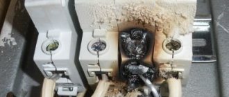
And the last reason is the failure of the circuit breaker itself. After several reactions to a series of increased currents, short-circuit faults, and arc extinguishing, it becomes unusable, which can be determined by external signs. If the terminals are charred or the plastic has melted, the device must be replaced.
Let's move on to connecting the circuit breaker
If there is voltage on your supply wire, it must be turned off before starting work. Then make sure there is no voltage on the connected wire using a voltage indicator. For connection we use VVGngP 3*2.5 three-core wire, with a cross-section of 2.5 mm.
We prepare suitable wires for connection. Our wire has double insulation, common outer and multi-colored inner. Let's decide on the connection colors:
- blue wire - always zero
- yellow with green stripe - earth
- the remaining color, in our case black, will be the phase
Phase and neutral are connected to the terminals of the machine, ground separately to the feed-through terminal. We remove the first layer of insulation, measure the required length, and bite off the excess. Remove the second layer of insulation from the phase and neutral wires, about 1 centimeter.
Unscrew the contact screws and insert the wires into the contacts of the machine. We connect the phase wire on the left, and the neutral wire on the right. Outgoing wires should be connected in the same way. After connecting, be sure to check again. Care must be taken to ensure that the wire insulation does not accidentally get into the clamping contact, as this will cause the copper core to have poor pressure to the machine contact, which will cause the wire to heat up, the contact to burn, and the result will be failure of the machine.
We inserted the wires, tightened the screws with a screwdriver, now you need to make sure that the wires are securely fixed in the contact clamp. We check each wire separately, swing it a little to the left, to the right, pull it up from the contact, if the wire remains motionless, the contact is good.
In our case, a three-wire wire is used; in addition to phase and zero, there is a grounding wire. In no case is it connected through a circuit breaker; a feed-through contact is provided for it. Inside, it is connected by a metal bus so that the wire passes without breaking to its final destination, usually sockets.
If you don’t have a feed-through contact at hand, you can simply twist the incoming and outgoing wires together using a regular twist, but in this case you need to pull it well with pliers. An example is shown in the picture.
The feed-through contact is installed as easily as a machine; it snaps onto the rail with a slight movement of the hand. We measure out the required amount of grounding wire, bite off the excess, remove the insulation (1 centimeter) and connect the wire to the contact.
Do not forget to make sure that the wire is well fixed in the contact clamp.
Suitable wires are connected.
If the circuit breaker trips, the voltage remains only on the upper contacts; this is completely safe and is provided for in the circuit breaker connection diagram. The lower contacts in this case will be completely disconnected from the electric current.
We connect the outgoing wires. By the way, these wires can go anywhere to a light, an outlet, or directly to equipment, for example, to an electric water heater or electric stove.
We remove the outer insulation and measure the amount of wire required for connection.
We remove the insulation from the copper conductors and connect the wires to the machine.
Prepare the ground wire. We measure out the required amount, clean it, connect it. We check the reliability of fixation in contact.
The connection of the circuit breaker has come to its logical conclusion, all wires are connected, and voltage can be applied. At the moment, the machine is in the down position (off), we can safely apply voltage to it and turn it on, to do this we move the lever to the up position (on).
By connecting the circuit breaker with our own hands, we saved:
- calling an electrician - 200 rubles
- installation and connection of a two-pole circuit breaker - 300 rubles
- DIN rail installation - 100 rubles
- installation and connection of a feed-through grounding contact 150 rubles
TOTAL: 750 rubles
*The cost of electrical installation services is shown in the pricing table
The structure and operating principle of a three-pole circuit breaker
A 3-pole circuit breaker consists of 3 single-pole devices housed in one housing and sharing a common switch lever. There are electromagnetic and thermal releases inside the protection device.
Internal organization
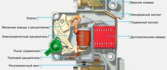
The electromagnetic release responds instantly to short circuit currents. According to the principle of operation, it resembles an ordinary electromagnet. If a short-circuit current flows through the machine, the electromagnetic release attracts the armature and sets the mechanics of the machine in motion. It opens the contacts of power circuits.
Circuit breaker design
The thermal release is similar to a bimetallic plate that is deformed by heat. It is characterized by slow response. To turn off the machine using the thermal release, it takes time for it to warm up to the desired temperature. Heat for heating is taken from the overload current flowing through the machine. Something similar is found in iron thermostats and kettle buttons.
Inside the differential automatic machines there is an additional unit - a current sensor. It is designed to compare currents flowing through phases. This design element allows the differential circuit breaker to turn off when voltage is lost in one of the phases. This function is especially important for the protection of electric motors.
Important! If your machine triggers without obvious overload, then you should pay attention to the reliability of its connection. Often, poor loose contact leads to heating of the machine. And heating leads to involuntary activation of the thermal release
And heating leads to involuntary activation of the thermal release.
Powerful three-pole circuit breakers have arc chutes. They are designed to interrupt the arc that forms between the contacts as quickly as possible at the moment the circuit opens. The use of arc chutes significantly extends the service life of the device. Thanks to them, contacts burn out much more slowly.
External elements
From the outside, the device has a standard design for protective devices. On top there are 3 screw terminals for connecting incoming wires. Below are similar screw contacts, but for the outgoing line. Between them there is an on and off lever. Many three-pole circuit breakers are equipped with a status indicator. Red flag or symbol “1” - the machine is turned on. Green or “0”—off. The main electrical parameters are indicated on the device body: rated current and time characteristic.
Additional Information. The design of some models of machines involves the use of a handle reminiscent of the one installed on the door. This handle is purchased at the buyer's request. Turning it turns the safety device on or off.
Machine device
The circuit breaker is a plastic case with contacts and an on/off handle. The working part is located inside. The stripped wire is inserted into the terminals and clamped with a screw. When cocked, the power contacts are closed - the handle position is “On”. The handle is connected to a cocking mechanism, which, in turn, moves the power contacts. Electromagnetic and thermal splitters ensure that the machine is switched off in case of abnormal circuit conditions. The arc chute prevents combustion and quickly extinguishes the arc. The exhaust channel removes combustion gases from the housing.
Difference between double-pole and single-pole circuit breaker
The difference between a single-pole and a double-pole switch is that the first monitors the technical parameters of several lines. Accordingly, the difference between two and three-pole is that in the first two lines are monitored, and in the second - three lines. When the voltage in one is exceeded, the device protects each line. The second device protects only one power line. At the same time, it is impossible to replace a two-pole circuit breaker with several single-pole ones due to the shutdown lever. The interlock is designed so that if there is a problem, both lines will be disconnected. In addition, the current will not evaporate. It will penetrate into a properly working device and a fire may occur.
Difference between double-pole and single-pole circuit breaker
Advantages and disadvantages
The advantages include reliable protection, the ability to control power, and ease of installation and maintenance. The main advantage is the de-energization of several conductors, regardless of the occurrence of an accident in any of them. Thanks to this, tension is completely removed.
You might be interested in: Installation of an electric meter
The disadvantages of a multi-pole protective device are the possibility of cable breakdown by electric current during a simultaneous short circuit of several electrical networks.
Note! They also include turning off the power to the electrical wiring during a breakdown of the thermal release, the inability to turn on the power after an emergency line breakdown and sensitivity to mechanical damage
Specifications
Technical characteristics of two-pole circuit breakers vary depending on price and manufacturer. The rated voltage is 240 watts, the rated current is from 6 to 63 amperes, the number of poles is from 1 to 4, the time-current characteristic is designated B, C and D.
Technical characteristics of electrical equipment
Installation and connection diagrams
A two-pole circuit breaker is installed according to the electrification plan. The housing is checked for damage and deformation before installation. The operation of the shutdown handle must be of high quality. During installation, the connection of a copper conductor using a lug and the connection of an aluminum cable using an end piece are taken into account. The upper group of stationary circuit breakers, conductor sealing with insulating tubes and protective tape, the distance of nodes and the location of the additional box are also taken into account.
The machine is placed on part of the DIN rail. The latch bracket is removed using a flat-head screwdriver and placed on the rail with fasteners. During installation, the usual scheme is used. An input switch is placed before the meter, after it a two-pole type device is mounted, and a neutral with a phase is connected on top. The cores are routed from below to the circuit. Wired copper jumpers are used to connect multiple devices together. The end is cleaned using a sharp object and crimped using a crimper.
Note! During installation of the device, work must be carried out by two specialists wearing protective rubber gloves after obtaining permission from the housing and communal services. The connection must be made to the panel without damage at the mounting location
Why is electrical knowledge necessary?
Information about electrical devices known from school physics lessons is not enough for practical use.
The average consumer more often encounters circuit breakers, since they are the ones that trip due to network overloads. It is not enough to simply return the lever to its usual position; you must definitely understand the reasons for the shutdown, otherwise the situation may repeat itself in the near future.
To navigate the electrical panel (which, by the way, is a mandatory element of the energy system of private houses), you need to know the composition and purpose of all devices - pulse relays, load switches, RCDs, etc.
Do you need to be able to change the automation yourself? We recommend that you first study the theory, and at the first shutdown, practice.
The fact is that it is not always possible to get quick help from professionals: on days off, electricians rest like everyone else. And if the house is located in a country house or in a village, it is better to become thoroughly familiar with the electrical network and related devices.
How to properly connect machines and RCDs
Before starting work on connecting the machines, it is necessary to prepare all the devices:
- Mounting rail (sometimes it is already included with the finished shield). In other cases, you will need to measure the required length yourself and cut it with metal scissors.
- Screwdriver.
- Wire cutters.
- Wire stripper.
Connecting machines and RCDs - step-by-step instructions
Step 1. To begin, you should attach two buses to a metal DIN rail: neutral and ground. This is easy to do; you just need to insert them at one end and then snap them into place.
This is what the tires should look like after installation.
Step 2. Now you need to secure the machines in series. At the bottom they have a special latch, which you just need to pull down and then secure the machine to the rail.
Each machine must be secured to the rail one by one.
Step 3. Next you need to take a three-core cable. As a rule, the ground wire is yellow, the neutral is blue, and the phase is white or pink (as in our case).
It is important not to mix up the power cable wires
Step 4. First we need to connect the neutral wire to the neutral bus. This is easy to do - you just need to unscrew the bolt with a screwdriver.
There is a hole for cables of different sections
Step 5. Now you need to connect the yellow ground wire to the ground bus.
This is done in the same way as in the previous version.
Step 6. The next step is to secure the power wire (pink). Contrary to many opinions, it should always come from the top. You should connect the wire, but you shouldn’t tighten it right away - the reason is that you will then have to supply the power wire to all other machines.
In this step, the wiring is connected “live”
Step 7. Seventh: you need to insert the power wire into the upper machine, and then insert one end of the additional jumper into the same hole.
Now you need to insert the jumper into the adjacent machine, and then into the other, alternately tightening the screws
Step 8
Now you need to pay attention to the last differential machine. On its body, as a rule, there is a connection diagram
The first input here will be designated by the letter N - this will be zero, the second input will be designated as I (L) - this will be the phase.
Step 9. Now it has become clear that the phase is at the second input, which means that the other end of the yellow jumper wire should be secured there. We tighten the screw by analogy with the previous options.
Thus, we have completed connecting the power cable that comes from the shield
Step 10. Now you need to connect the wires that come from the room. First, you will need to remove the insulation layer from their ends. A special tool is used to strip the ends of the wires.
Here you can turn the screw and set the wire thickness
Step 11. Here you should also connect the neutral wire to the corresponding bus.
You can unscrew any loose bolt
Step 12: Now you need to secure the ground wire again.
The wire must be tightened carefully, without catching the insulation layer.
Step 13. Now from below we fix the power wire that comes from the electrical device.
The following wiring, by the same analogy, will be connected only from below
Step 14. Now you need to take an additional wire, connect it to the zero bus, and then to the first input on the differential machine.
We fix the wire in the first hole of the difavtomat
Electrical panel for meters and machines: choosing an installation location
Let's start with the simplest part - where to place the switchboard in the apartment? It is most convenient to place it near the front door in the hallway. In this case, you will not have to pull the power cable far from the site. The best height option is at the eye level of an adult. And it’s convenient to take meter readings and turn off the machines if necessary.
For those who support pushing everything under the ceiling, “for greater security, like they used to hang meters,” let’s say the following. Old electric meters with fuse plugs were simply mounted on the wall without boxes, and therefore were hung from the ceiling.
A modern electrical panel has a durable casing and is locked, so children will not get in unless you leave the key in a visible place.
When choosing a location for installing a panel in a private house or cottage, you need to consider where and how the cable from the overhead line or underground supply line is or will be installed. Data on external networks can be obtained from local energy sales.
Buy a ready-made one or assemble an electrical panel yourself
As they say in the old song “what progress has come”, you can buy a ready-made shield with a full filling or assemble a ready-made one. If your electrician suggests such a “proprietary” assembly design, then do not be alarmed. The panels are assembled by enterprises and electrical installation companies, including on order or for standard residential wiring projects.
The main point that needs to be clarified is whether your master has worked with ready-made shields before or this is his first experience. If he has installed a dozen or two such assemblies and knows their features, then feel free to agree. But if you are a “guinea pig” for the first experiment, refuse. It’s better to let him assemble it himself, with his own hands, the old fashioned way.
Areas of application
3-phase circuit breakers are used wherever there is a three-phase power supply. Connecting consumers without these protective devices is a gross violation of the rules for electrical installations. It is pointless to list all examples of the use of three-phase machines. Too many of them. Therefore, below are electrical devices that are protected by three-phase circuit breakers, but to some extent are found in the life of every person:
- street lighting networks;
- three-phase asynchronous motors of elevator equipment;
- input distribution devices of residential buildings;
- protection of engines of children's attractions;
- engines of pumping stations that pump water to residential buildings;
- pumps pumping out sewage water are protected by three-phase circuit breakers.
Three-pole circuit breakers are used everywhere. Their use is mandatory wherever there is a 3-phase power supply. Three-pole protection devices are almost no different from single-pole ones. The differences lie only in the number of protected phases, maximum operating currents and overall dimensions.
When connecting a three-terminal network, it is necessary to take into account its timing characteristics and rated current. These parameters are indicated on the body of the protective device
You should also pay attention to the series of the machine. It is determined based on the conditions of future operation, that is, how often the device will be triggered by a short circuit, how many times a day it will be switched by hand
Description of the main parameters
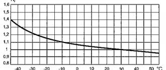
The rated current of any (including double) 25 Ampere machine is indicated in its marking. It means the value at which the device operates for a long time without turning off. This parameter is entered taking into account the average air temperature of 30°C. If it decreases, it will increase, and if it increases, on the contrary, it will decrease.
The current limit class indicates how long it takes to extinguish an arc that occurs when switching high currents. There are 3 known classes of switches that differ in this parameter:
- In the third class, the arc goes out in 3-5 milliseconds.
- In devices of the second group, it takes 5-10 milliseconds to extinguish it.
- For devices of the first class, the restriction is not standardized. The process usually occurs in 10 milliseconds or more.
The class marking is applied to the body in the form of numbers 3 or 2 placed in a frame.
| Rated current of the circuit breaker, A | Electrical circuit load, 220 V |
| 10 | Lighting, alarm |
| 16 | General purpose sockets |
| 25 | Air conditioners, water heaters |
| 32 | Electric stoves, ovens |
| 40; 50 | General input |
Expert opinion
Strebizh Viktor Fedorovich, leading construction foreman
In order to decide which RCD is the best, when purchasing it, you must take into account all the parameters and technical characteristics. If you need an explanation of unclear points, write to me!
Overview of circuit breakers
The machine is connected between the current source and the electrical wiring, which should be protected. A three-pole circuit breaker consists of three contact pairs, each of which is connected in series with thermal and electromagnetic releases. The machine only disconnects the phases without breaking the neutral, which is not connected to it. If there is a need to disconnect the neutral wire, four-pole models are used. They are usually used on main inputs.
In apartments and private houses, class C machines are used for moderate loads. The current strength is selected according to the power of the connected devices, where the threshold value is twice the nominal value in order to eliminate false alarms.
The products of the companies IEK, EKF, DEK, INTES and Kontaktor are widely distributed. Domestic products have sufficient reliability and reasonable prices. Automatic machines with 16 A and 25 A are widely used. Imported ones are more expensive, but well-known companies produce high-quality and reliable models. For a three-pole automatic switch, the price of well-known companies may vary greatly, but it is quite consistent with the quality.
A protective device with three-phase current is used at the entrance to the house and to power professional machines with a voltage of 380 V, for example, a three-pole 100A automatic switch.
The meter must correspond to this power if it is located after the switch. Usually it is no more than 63 A. A more powerful three-pole circuit breaker is used in industry.
From the reviews and advice of experienced electricians, it follows that machines with inflated ratings should never be used. This poses a risk of fire or equipment failure.
A four-core wire with three phases and a working zero is supplied to residential buildings. They rarely use equipment designed for 380 V. The phases in the distribution panel are separated. This results in 3 separate lines with a voltage of 220 V.
The advantage of multi-pole machines is the ability to control several lines simultaneously. By installing a three-pole 25A automatic switch on three devices of the appropriate power, you can control each individual line. If a short circuit occurs on one of them, all of them will turn off at once. Typically, additional single-phase switches are installed on each line. If one of them fails, the three-phase one will operate, which increases the reliability of the system.
Types of packet switches: ouzo, contactors, packets
- A machine with which type of electromagnetic release to choose. In everyday life, machines of categories “B” and “C” are most often used. This is due to the fastest possible operation of package switches when the rated current is exceeded. This is extremely important when using appliances such as electric kettles, toasters and irons. Depending on the type of equipment used, you should choose a specific category; it is advisable to give preference to category “B” switches.
- A machine with a maximum switching capacity to choose. Depends on the location of the electricity input from the substation to the apartment, if in close proximity, then you should choose one with a switching capacity of 10,000 amperes, otherwise for city apartments there are enough devices for 5,000–6,000 amperes. You can play it safe and choose the option of 10,000 amperes; ultimately, this indicator only affects whether the machine will be operational after a short circuit.
- What type of wire to choose: aluminum or copper We strongly do not recommend purchasing aluminum conductors. Copper wiring is more durable and can handle higher currents.