There are times in life when a low-voltage power source for fluorescent lamps . Such a lamp can be powered by a rechargeable battery while camping or in the country, and can also easily find its use in the garage and at home; it can even start a burnt-out fluorescent lamp.
Main functions
It is not possible to connect fluorescent light sources directly to the electrical network. There are the following reasons for this:
- to create a persistent discharge in a fluorescent lamp, it is necessary to preheat its electrodes and apply a starting pulse to them;
- Since gas-discharge light sources have a negative differential resistance, they are characterized by an increase in current strength after entering the operating mode. It must be limited to prevent the light source from failing.
Based on the reasons described above, it is necessary to use ballasts.
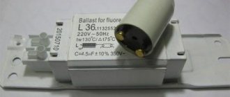
Electromagnetic type ballasts
Principle of operation
Let's consider the principle of operation of an electromagnetic choke using the example of a typical connection diagram for gas-discharge lamps.
Typical connection diagram
The diagram shows:
- EL – gas-discharge (fluorescent) type lamp;
- SF is a starter, it is a device consisting of a flask filled with an inert gas, inside it there are bimetal contacts. A capacitor is installed parallel to the flask;
- LL – choke (electromagnetic);
- lamp spirals (1 and 2);
- C – capacitor (compensates for reactive power), its capacity depends on the power of the lamp, the correspondence table is shown below.
| Gas discharge source power (W) | Capacitor capacity (uF) |
| 15 | 4,50 |
| 18 | 4,50 |
| 30 | 4,50 |
| 36 | 4,50 |
| 58 | 7,00 |
There are devices in the circuits of which there is no compensating capacitor; this is unacceptable, since reactive load leads to the following negative consequences:
- there is an increase in power consumption, which leads to increased energy consumption;
- The service life of the equipment is significantly reduced.
Now let's move directly to the principle of operation of the above typical scheme. Conventionally, it can be divided into the following stages:
- when connected to the mains, a current begins to flow through the circuit inductor “LL” – spiral “1” – starter “SF” – spiral “2”, the strength of which is from 40 to 50 mA;
- under the influence of this process, an inert gas is ionized in the starter flask, which leads to an increase in current strength and heating of the bimetallic contacts;
- the heated electrodes in the starter close, this causes a sharp increase in current, up to approximately 600 mA. Its further growth limits the inductance of the inductor;
- due to the increased current in the circuit, the spirals (1 and 2) are heated, as a result of which electrons are emitted by them, the gas mixture is heated, which leads to a discharge;
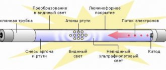
- Under the influence of the discharge, ultraviolet radiation appears, which hits the phosphor coating. As a result, it glows in the visible spectrum;
- when the light source “lights up”, its resistance decreases, and accordingly, the voltage at the inductor decreases (up to 110 V);
- The starter contacts cool down and open.
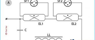
Tandem connection
Below is a diagram where two fluorescent type lamps are connected in series.
Tandem connection diagram
The operating principle of the presented circuit does not differ from a standard connection, the only difference is in the parameters of the starters. For a two-lamp connection, starters are used whose “breakdown” voltage is 110 V (type S2), for a single-lamp connection - 220 V (type S10).
Starters S10 and S2 for 220 and 110 V respectively
Converter for fluorescent lamp - assembly
To demonstrate the functionality of the circuit, it was assembled on a breadboard. The circuit is powered from the breadboard power supply - 5V. The transformer is removed from the power supply and turned on in reverse, i.e. a winding with a large number of turns goes to the contacts of the fluorescent lamp. The transistor heats up during operation, it is advisable to install it on at least a small radiator. After an hour of working with the radiator, it became simply warm.
Our very first test lamp was an 8 W lamp. The glow is quite bright, its brightness is slightly different from turning it on in the standard way.
The second 18 W lamp came on, but very dimly. The power that this voltage converter produces for such a fluorescent lamp is clearly not enough.
In general, given the simplicity of this circuit, it can be safely recommended for assembly. If necessary, the circuit can be powered from 12 V , but in this case 5 V stabilizer is required to power the microcircuit.
comments powered by HyperComments
Features of electromagnetic type chokes
Speaking about the features of electromagnetic ballasts, it should be noted that the only advantages of these devices are their relatively low price, simple operation and simple installation. The classical connection scheme has much more disadvantages :
- the presence of a bulky and “noisy” throttle;
- starters, unfortunately, are not reliable;
- the presence of a strobe effect (the lamp flickers at a frequency of 50 Hz) causes increased fatigue in a person, which leads to a decrease in his performance;
- when the starters fail, a false start occurs, that is, the lamp flashes several times before “lighting up”, this reduces the working life of the light source;
- approximately 25% of the power is spent on electromagnetic ballast, resulting in a significant reduction in efficiency.
The use of electronic ballasts allows you to get rid of most of the disadvantages listed above.
Welcome to our store
Recessed ceiling fluorescent luminaires produced by Philips Lighting have gone on sale.
Designed to meet energy-efficient primary lighting needs, the TBS165 (260) saves energy by replacing legacy electromagnetic installations with Philips TL5 technology. With innovative dedicated TL5 optics, a choice of ballasts, sensors (occupancy detection, daylight control) and emergency lighting, the TBS165(260) series can be used for general lighting in a wide range of applications including offices, corridors, schools and shops.
By combining high-frequency ballasts, sensors and MASTER TL5 lamps, this allows for significant energy savings. Low height recessed luminaire suitable for open ceilings. Conveniently, it does not need to be opened since it has pre-installed lamps and can be connected from the outside.
TBS260 4xTL5-14W/840 HFS P PI Features: - High frequency ballast - Prismatic diffuser
TBS165 G 4xTL5-14W/840 HFS M2 PIP SC Features: - High frequency ballast - Brushed aluminum grille with matte cross plates - Anti-pull clamp
TBS165 K 4X14W/840 HFP C6 EL1 PIP SC Features: - High frequency hot start ballast - High reflective aluminum grille with 3D reflective plates - Emergency lighting (built-in): 1 hour (EL1) - Anti-pull clamp
also offer to your attention
waterproof
wall lamp Philips myGarden
from the OuterStylers collection. Thanks to IP44 protection against dust and moisture, as well as a matte diffuser, this lamp will create a cozy atmosphere outdoors, in the garden or on the veranda.
You can learn more about the characteristics of these lamps, get advice or check the price by calling: (495) 925-15-06, or by visiting our retail store at: Simferopol Boulevard 11/12, TC “Moskvoretsky”.
Reduced prices for electronic ballasts for metal halide lamps
Dear customers and site guests! In continuation of the campaign to reduce prices for metal halide lamps, we would like to bring to your attention electronic ballasts for metal halide lamps Osram Powertrotic PTi
– also at new reduced prices.
| Powertrotic PTi 35/220-240 S , Powertrotic PTi 70/220-240 S | Powertroinc PT-Fit 35W/220-240 S , Powertroinc PT-Fit 70W/220-240 S | Tridonic 35W/70W |
The presented electronic ballasts are designed to start metal halide lamps with a power of 35 W and 70 W, respectively. The low weight and compact dimensions of Powertronic electronic ballasts ensure a very wide range of applications in small, elegant luminaires. The devices have a long service life, which is ensured by excellent thermal characteristics, allowing the device to remain operational at high temperatures. This is also facilitated by a high-quality metal housing for optimal contact between the electronic ballast and the luminaire.
A separate niche is occupied by universal electronic ballasts for metal halide lamps of the Tridonic series. These are the so-called Multiwatt electronic ballasts - they are designed to work with both a 35-watt metal halide lamp and a 70-watt one.
| Powertrotic PTi 150/220-240 S | Powertronic PTi 20/220-240 S |
Electronic ballast for low-power metal halide lamps (20 W). Increased lumen stability and reduced light scattering extends lamp life. The devices have the function of turning off faulty lamps. The ability to control the thermal regime completely eliminates system overheating and short circuits. Compact dimensions and low weight allow the electronic ballast to be placed next to the lamp or built into it.
Metal halide lamps – promotion!
sale!
Despite the growing popularity of LED light sources, metal halide lamps confidently occupy a leading position among professional lighting systems and architectural lighting.
The brightness of metal halide lamps remains virtually unchanged throughout their entire service life, and the operation of the lamps is very stable. High color rendering ensures realistic lighting and allows you to convey a variety of colors and shades. Thanks to this, metal halide lamps have found wide application in lighting exhibitions and trade pavilions.
announces the promotion “Metal halide lamps at a super price”. The following products are included in the promotion:
| Metal halide lamps with ceramic burners POWERBALL HCI-T | |||||||
| Name | Code | Power | Light flow | Base | Price | ||
| HCI-T 35/830 WDL PB | 520258 (005625) | 35 W | 3600 lm | G12 | |||
| HCI-T 70/830 WDL PB | 523402 (873664) | 70 W | 7300 lm | G12 | |||
| Metal halide lamps with quartz burners POWERSTAR HQI-T | |||||||
| Name | Code | Power | Light flow | Base | Price | ||
| HQI-T 70/830 WDL | 524775 (873008) | 70 W | 5300 lm | G12 | |||
| HQI-T 70/942 NDL | 527899 (872988) | 70 W | 5800 lm | G12 | |||
| HQI-T 150/830 WDL | 524836 (872865) | 150 W | 13000 lm | G12 | |||
| Metal halide lamps MASTER Color CDM-T | |||||||
| Name | Code | Power | Light flow | Base | Price | ||
| CDM-T 35W/830 | 19697215 | 35 W | 3300 lm | G12 | |||
| Metal halide lamps with ceramic burners POWERBALL HCI-TS | |||||||
| Name | Code | Power | Light flow | Base | Price | ||
| HCI-TS 70/830 WDL PB | 523525 (784069) | 70 W | 6800 lm | RX7s | |||
| HCI-TS 70/942 NDL PB | 523549 (784106) | 70 W | 6500 lm | RX7s | |||
| HCI-TS 150/830 WDL PB | 517814 (783987) | 150 W | 14500 lm | RX7s-24 | |||
| HCI-TS 250/830 WDL MD PB | 519672 (637730) | 250 W | 25000 lm | Fc2 | |||
| HCI-TS 250/942 NDL MD PB | 519696 (552245) | 250 W | 25000 lm | Fc2 | |||
| Metal halide lamps with quartz burners POWERSTAR HQI-TS | |||||||
| Name | Code | Power | Light flow | Base | Price | ||
| HQI-TS 250/830 WDL | 525130 (689177) | 250 W | 22000 lm | Fc2 | |||
| HQI-TS 250/942 NDL | 525178 | 250 W | 20000lm | Fc2 | |||
| Metal halide lamps MASTER Color CDM-TD | |||||||
| Name | Code | Power | Light flow | Base | Price | ||
| CDM-TD 70W/942 | 20002015 | 70 W | 6000 lm | RX7s | |||
| CDM-TD 150W/942 | 20025915 | 150 W | 14200 lm | RX7s | |||
| Metal halide lamps with ceramic burners POWERBALL HCI-TC | |||||||
| Name | Code | Power | Light flow | Base | Price | ||
| HCI-TC 35/830 WDL PB | 517739 (876870) | 35 W | 3500 lm | G8.5 | |||
| HCI-TC 70/830 WDL PB | 521040 (907639) | 70 W | 6900 lm | G8.5 | |||
| Metal halide lamps MASTER Color CDM-TC | |||||||
| Name | Code | Power | Light flow | Base | Price | ||
| CDM-TC 70/830 | 20167615 | 70 W | 6500 lm | G8.5 | |||
| Metal halide lamps MASTER Color CDM-T Elite | |||||||
| Name | Code | Power | Light flow | Base | Price | ||
| CDM-T Elite 70W/930 | 20815615 | 70 W | 7300 lm | G12 | |||
| Metal halide lamps MASTER Color CDM-TC Elite | ||||||
| Name | Code | Power | Light flow | Base | Price | |
| CDM-TC Elite 70W/930 | 091153400 | 70 W | 7300 lm | G8.5 | ||
| Metal halide lamps MASTER Color CDM-R111 | |||||||
| Name | Code | Power | Corner | Light intensity | Base | Price | |
| CDM-R111 35W/830 | 20448610 | 35 W | 10* | 35000 CD | GX8.5 | ||
| CDM-R111 35W/830 | 20450910 | 35 W | 24* | 8500 cd | GX8.5 | ||
| CDM-R111 35W/830 | 20452310 | 35 W | 40* | 4000 cd | GX8.5 | ||
| CDM-R111 70W/830 | 20719710 | 70 W | 10* | 50000 cd | GX8.5 | ||
| CDM-R111 70W/830 | 20721010 | 70 W | 24* | 15000 cd | GX8.5 | ||
| CDM-R111 70W/830 | 20723410 | 70 W | 40* | 9000 CD | GX8.5 | ||
| Miniature metal halide lamps MASTER Color CDM-Tm Mini | |||||||
| Name | Code | Power | Light flow | Base | Price | ||
| CDM-Tm Mini 20W/830 | 20751715 | 20 W | 1650 lm | PGj5 | |||
| CDM-Tm Mini 35W/930 | 21149115 | 35 W | 3000 lm | PGj5 | |||
Sale! New lamps at reduced prices.
| High pressure mercury lamps (HPL) | |||||||
| Name | Code | Power | Light flow | Base | Price | ||
| HPL-N 250W/542 | 18060515 | 250 W | 12700 lm | E40 | |||
| Mixed light mercury lamps (MLVs) | |||||||
| Name | Code | Power | Light flow | Base | Price | ||
| ML 250W/534 | 20129415 | 250 W | 5500 lm | E40 | |||
| ML 500W/534 | 20133110 | 500 W | 13000 lm | E40 | |||
| Quartz metal halide lamps | |||||||
| Name | Code | Power | Light flow | Base | Price | ||
| HPI Plus 400W/645 | 18252400 | 400 W | 32500 lm | E40 | |||
| Quartz metal halide lamps with tubular bulb | |||||||
| Name | Code | Power | Light flow | Base | Price | ||
| HPI-T Plus 250W/645 | 17989015 | 250 W | 20500 lm | E40 | |||
| HPI-T Plus 400W/645 | 17990615 | 400 W | 35000 lm | E40 | |||
| High pressure sodium lamps with tubular bulb | |||||||
| Name | Code | Power | Light flow | Base | Price | ||
| SON-T PIA Plus 250W | 17987615 | 250 W | 33200 lm | E40 | |||
| GreenPower high pressure sodium lamps (for greenhouses) | |||||||
| Name | Code | Power | Light flow | Base | Price | ||
| GreenPower 600W 230V | 20202415 | 600 W | 88000 lm | E40 | |||
| GreenPower 600W 400V | 20307615 | 600 W | 87500 lm | E40 | |||
read more
Electronic ballast (EPG)
Electronic ballasts appeared en masse not so long ago, about thirty years ago, and now they have practically replaced electromagnetic devices. This was facilitated by numerous advantages over the classical switching circuit; we will name the main ones:
- increasing the luminous efficiency of fluorescent lamps due to high-frequency discharge;
- absence of noise characteristic of low-frequency electromagnetic chokes;
- reducing the gating effect significantly expanded the scope of application;
- the absence of a false start increases the service life of luminescent sources;
- Efficiency can reach 97%;
- compared to electromagnetic type ballasts, energy consumption is reduced by 30%;
- there is no need to compensate for reactive load;
- Some models of electronic devices provide control of the power of the lighting source; this is done by adjusting the frequency in the voltage converter.
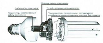
EPLA appearance and internal structure
It is also worth noting: due to the absence of a bulky inductor, it became possible to reduce the size of the electronic ballast, which made it possible to place it in the base. This significantly expands the scope of application, making it possible to use it in lighting devices instead of sources that use a filament.
Electronic ballast located in the base
As an example, let's take a simple electronic ballast circuit, typical of most inexpensive devices.
Diagram of a typical electronic ballast
List of elements:
- resistor ratings: R1 and R2 -15 Ohm, R3 and R4 – 2.2 Ohm, R5 – 620 kOhm, R6 – 1.6 Mohm;
- capacitors used: C1 – 47 nF 400 V, C2 – 6800 pF 1200 V, C3 – 2200 pF, C4 – 22 nF, C5 – 4.7 µF 350 V;
- diodes: VD1-VD7 – 1N400;
- transistors: T1 and T2 – 13003;
- diode triac VS – DB3.
Concluding the topic of electronic ballasts, it is necessary to note that their significant drawback is the relatively high cost of high-quality devices. As for inexpensive models, their reliability leaves much to be desired.
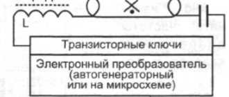
Energy-saving lamp from a low-voltage power source - diagram
The voltage converter for a fluorescent lamp conventionally consists of three parts.
- Master generator of rectangular pulses on the K155LA3 or K555LA3 (you can take any other analogue). Our generator is assembled on K555LA3.
- Field effect transistor IFRZ44N , controlled by a generator, the load of which includes the transformer winding
- Step-up transformer
The rectangular pulse generator on the K155LA3 microcircuit is controlled using a construction resistor R1. T1 KT315 transistor with an LED is connected to the output of the generator , which will visually help control the frequency and operation of the generator.
At different frequencies, the operating modes of the transistor and transformer will change, and the fluorescent lamp will glow with different brightness. Using a construction resistor, it is necessary to select the frequency at which there will be an optimal balance between the current flowing through transistor T2 and the brightness of the fluorescent lamp. The frequency will be approximately 70 - 120 Hz .
Connection without ballast
If necessary, gas-discharge light sources can be connected to the power supply without electromagnetic or electronic ballast. The diagram of such a connection is shown below.
Throttleless connection method
To implement such a connection you will need:
- fluorescent lamp - 40 W and incandescent lamp - 60 W (the latter will work as a ballast resistance);
- two capacitors 0.47 uF 400 V (play the role of a multiplier);
- diode bridge KTs404A or similar, you can use four diodes designed for a current of at least 1 A and a reverse pulse voltage of 600 V.
This circuit is inferior in its parameters to connection using an electromagnetic choke and electronic ballasts. It is provided for informational purposes only.
A simple voltage converter for powering a fluorescent lamp
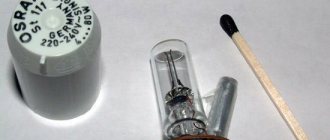
The technical literature describes many voltage converter circuits for powering fluorescent lamps, but for most of them it is necessary to make a transformer yourself. The author offers his own version of the converter using as a transformer a television TBC (output line transformer - “line transformer”) type TVS-110LA from a black-and-white TV with a slight modification.
TVS-110LA
The converter ensures operation of a fluorescent lamp from a 12 V power source. It provides ignition and combustion of fluorescent lamps with a power of 6 to 40 W. A special feature of the device is that it can work with a fluorescent lamp whose filaments are broken (burnt out).
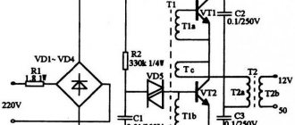
The electrical circuit diagram of the converter is shown in Figure . As can be seen from the diagram, the basis of the device is a classic multivibrator. TVS-110LA with minor modifications was used as the converter transformer. The mounting aluminum plate in the transformer is removed and instead of this plate a strip of fiberglass is installed, in which two holes must be drilled for the studs.
Voltage converter circuit for powering a fluorescent lamp
There is no need to disassemble the TBC, except to remove the high-voltage winding, but this is not necessary. Then the ferrite rod, together with the installed strip, must be wrapped in thick paper and wound 16 turns into two PEV-2 wires with a diameter of 0.8 mm - these will be windings I and II, which must be connected in series in phase, i.e. connecting the end of the first winding to the beginning of the second. The remaining TBC windings are used unchanged. The number of turns of TVS-110LA windings, in accordance with [1], is:
- high-voltage winding: 1200 turns of PEV-2 wire with a diameter of 0.1 mm;
- winding III (pins 4-9) contains 960 turns, of which winding 4-5 contains 80 turns of PEV-2 wire with a diameter of 0.41 mm, the rest - PEV-2 with a diameter of 0.23 mm;
- winding IV (terminals 1-3) - 96 turns PEV-2 0.23 mm.
To power the fluorescent lamp, two series-connected windings III and IV are used.
If there is a need to increase the output voltage, then to do this you should reduce the number of turns of windings I and II, but leave at least 10 turns. Transistors VT1, VT2 must be installed on radiators with S=50 cm2. Instead of the KT808A transistor, you can use KT805 transistors with any letter indices.
The converter can be powered from a TP7-12 battery (12 V, 7 Ah).
In conclusion, we note the following:
- as experiments show, the high-voltage winding (V) is also suitable for powering a fluorescent lamp;
- If the high-voltage winding in the transformer is faulty, then it is better to remove it.
Literature
- Kuznets L.M., Sokolov V.S. Television receiver units. Ref. - M.: Radio and Communications, 1987.
- Brezhnev KM and others. Transistors for equipment of wide application. Ref. — M.: Radio and communications. 1981.
Author: Svyatoslav Babyn, village Kelmentsi, Chernivtsi region.
Source: Radioamator No. 2, 2015