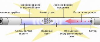
When the lamp is turned on, an electronic discharge occurs in the mercury vapor that fills the test tube and the resulting UV radiation affects the phosphor coating. Let's consider several options.
Tandem connection Below is a diagram where two fluorescent type lamps are connected in series. Connecting a fluorescent lamp Electronic ballast for two fluorescent lamps The advantages of electronic ballasts are described in the video. The simplest option is a self-oscillator converter circuit with 1 transistor.
To eliminate these shortcomings, electronic ballast control equipment circuits have been developed. After the time has elapsed, a high-voltage pulse is applied, which causes the discharge to ignite between the electrodes.
The switching circuit is designed in such a way that it has one choke for two light bulbs.
Perhaps one of the electrode threads has burned out. After which, due to the energy accumulated in the inductor, a voltage surge occurs and a glow discharge occurs in the lamp.
Scheme for switching fluorescent fluorescent lamps through an electromagnetic choke and starter.
The device of fluorescent lamps
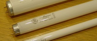
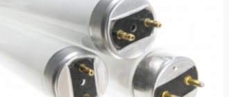
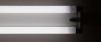
In most light bulbs, the bulb is shaped like a cylinder. More complex geometric shapes are found. At the ends of the lamp there are electrodes, reminiscent in design of the spirals of incandescent light bulbs. The electrodes are made of tungsten and soldered to the pins located on the outside. Voltage is applied to these pins.
A gas environment is created inside the fluorescent lamp, which is characterized by negative resistance, which manifests itself when the voltage between the electrodes located opposite each other decreases.
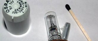
The lamp switching circuit uses a choke (ballast). Its task is to generate a significant voltage pulse, due to which the light bulb will turn on. The kit includes a starter, which is a glow discharge lamp with a pair of electrodes in an inert gas environment. One of the electrodes is a bimetallic plate. When turned off, the electrodes of the fluorescent light bulb are open.
The figure below shows a diagram of the operation of a fluorescent lamp.
Warm-up time
DRL 250 lamps begin to burn as much as possible (the characteristics of the devices will be indicated below) approximately 7-10 minutes after they are put into operation. It takes so much time because mercury in an unheated state, located in a quartz burner, is presented in the form of droplets or a thin layer on the walls of the glass flask. But after turning on the lamp, high temperature begins to act on this liquid metal, and this in turn leads to the evaporation of mercury and a gradual improvement in the discharge between the existing electrodes. At the moment when all the mercury is completely converted into gaseous form, the DRL lamp will begin to operate in its nominal mode.
How does a fluorescent lamp work?
The operating principles of fluorescent light sources are based on the following principles:
- Voltage is sent to the circuit. However, at first the current does not reach the light bulb due to the high voltage of the environment. The current moves through the spirals of the diodes, gradually heating them. The current is supplied to the starter, where the voltage is sufficient to produce a glow discharge.
- As a result of the heating of the starter contacts by the current, the bimetallic plate shorts. The metal takes on the functions of a conductor, and the discharge ends.
- The temperature in the bimetallic conductor drops, and the contact in the network opens. The inductor creates a high voltage pulse as a result of self-induction. As a result, the fluorescent light bulb lights up.
- A current flows through the lighting fixture, which is halved as the voltage across the inductor is reduced. It is not enough to start the starter again, the contacts of which are open when the light is on.
To create a circuit for switching on two light bulbs installed in one lighting fixture, you need a common choke. The lamps are connected in series, but each light source has a parallel starter.
Life time
Machine 16k20f3: technical characteristics and description
, according to the manufacturers, such a light source is capable of burning for at least 12,000 hours. Here everything depends on such a characteristic as power - the more powerful the lamp, the longer it lasts.
Popular models and how many hours of service they are designed for:
- DRL 125 - 12000 hours;
- 250 - 12000 hours;
- 400 - 15000 hours;
- 700 - 20000 hours.
Note! In practice, the numbers may be different. The fact is that electrodes, like the phosphor, can fail faster
As a rule, light bulbs cannot be repaired; they are easier to replace, since a worn-out product shines 50% worse.
Products are designed for at least 12,000 operating hours
There are several varieties of DRL (meaning mercury arc lamp), which are applicable both in everyday life and in industrial conditions. Products are classified by power, with the most popular models being 250 and 500 W. Using them, street lighting systems are still being created. Mercury devices are good due to their accessibility and powerful luminous flux. However, more innovative samples are appearing, safer and with better glow quality.
Connection options
Let's consider different options for connecting a fluorescent lamp.
Connection using electromagnetic balance (EMB)
The most common type of connection for a fluorescent light source is a circuit with a starter, where electronic ballasts are used. The principle of operation of the circuit is based on the fact that as a result of connecting the power, a discharge occurs in the starter and the bimetallic electrodes are short-circuited.
The current in the electrical circuit of the conductors and starter is limited only by the internal choke resistance. As a result, the operating current in the light bulb increases almost threefold, the electrodes rapidly heat up, and after the conductors lose temperature, self-induction occurs and the lamp ignites.
Disadvantages of the scheme:
- Compared to other methods, this is a rather expensive option in terms of energy consumption.
- Start-up takes at least 1 – 3 seconds (depending on the degree of wear of the light source).
- Inability to work at low air temperatures (for example, in an unheated basement or garage).
- There is a stroboscopic effect of flashing the light bulb. This factor negatively affects human vision. Such lighting cannot be used for production purposes, because fast moving objects (for example, a workpiece in a lathe) appear motionless.
- Unpleasant humming of the throttle plates. As the device wears out, the sound increases.
The switching circuit is designed in such a way that it has one choke for two light bulbs. The inductance of the inductor should be enough for both light sources. 127 volt starters are used. They are not suitable for a single-lamp circuit; 220 Volt devices are needed there.
The picture below shows a chokeless connection. The starter is missing. The circuit is used in case of burnout of filament lamps. A step-up transformer T1 and a capacitor C1 are used, which limits the current flowing through the light bulb from a 220-volt network.
The following circuit is used for light bulbs with burnt out filaments. However, there is no need for a step-up transformer, making the design of the device simpler.
Below is shown a method of using a diode rectifier bridge, which eliminates the flickering of a light bulb.
The figure below shows the same technique, but in a more complex design.
Two tubes and two chokes
To connect a fluorescent lamp, you can use a serial connection:
- The phase from the wiring is sent to the inductor input.
- From the inductor output, the phase goes to the contact of the light source (1). From the second contact it is sent to the starter (1).
- From the starter (1) it goes to the second contact pair of the same light bulb (1). The remaining contact is connected to zero (N).
Connect the second tube in the same way. First the inductor, then one contact of the light bulb (2). The second contact of the group is sent to the second starter. The starter output is combined with the second pair of light source contacts (2). The remaining contact should be connected to input zero.
Connection diagram for two lamps from one choke
The scheme provides for the presence of two starters and one choke. The most expensive element of the circuit is the inductor. A more economical option is a two-lamp lamp with a choke. The video explains how to implement the scheme.
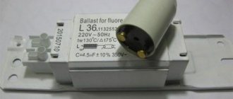
Electronic ballast
The disadvantages of the electronic ballast circuit necessitated the search for a more optimal connection method. During the research, a method involving electronic ballast was invented. In this case, it is not the mains frequency (50 Hz) that is used, but high frequencies (20 – 60 kHz). It is possible to get rid of the flashing light that is harmful to the eyes.
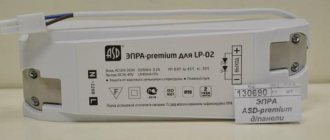
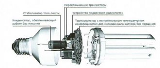
Externally, the electronic ballast is a block with terminals exposed to the outside. The inside of the device contains a printed circuit board on which the entire circuit can be assembled. The unit is small in size, thanks to which it fits into the housing of even a small lighting device. Switching on is much faster compared to the EMPA standard. The operation of the device does not cause acoustic discomfort. This connection method is called starterless.
It is not difficult to understand the principle of operation of a device of this type, since there is a diagram on its reverse side. It shows the number of lamps for connection and explanatory notes. There is information about the power of the light bulbs and other technical parameters of the device.
The connection is made as follows:
- The first and second contacts are connected to a pair of lamp contacts.
- The third and fourth contacts are directed to the remaining pair.
- Power is supplied to the input.
Using Voltage Multipliers
This option allows you to connect a fluorescent lamp without using an electromagnetic balance. Usually used to increase the service life of light bulbs. The connection diagram for burnt-out lamps makes it possible for the light sources to work for some more time, provided that their power is no more than 20 - 40 W. Filaments are allowed both suitable for work and burnt out. In any case, the thread leads must be short-circuited.
As a result of rectification, the voltage doubles, so the light bulb turns on almost instantly. Capacitors C1 and C2 are selected based on an operating voltage of 600 Volts. The disadvantage of capacitors is their large size. As capacitors C3 and C4, preference is given to mica devices rated at 1000 Volts.
Fluorescent lamps are not compatible with direct current. Very soon, so much mercury accumulates in the device that the light becomes noticeably weaker. To restore the brightness of the glow, change the polarity by turning the bulb over. Alternatively, you can install a switch so you don't have to remove the lamp every time.
Connection without starter
The method using a starter involves prolonged heating of the light bulb. In addition, this part must be changed frequently. A scheme where the electrodes are heated using old transformer windings allows you to do without a starter. The transformer acts as ballast.
Bulbs used without a starter must be marked RS (quick start). A light source started through a starter is not suitable, since its conductors take a long time to heat up and the spirals burn out quickly.
Serial connection of two light bulbs
In this case, it is necessary to connect two fluorescent lamps with one ballast. All devices are connected in series.
To carry out electrical work you will need the following parts:
- induction throttle;
- starters (2 units);
- fluorescent light bulbs.
The connection is made in the following order:
- We connect starters to each light bulb. The connection is made in parallel. The connection point is the pin input at the ends of the lighting device.
- We direct free contacts to the electrical network. We use a choke for connection.
- We connect capacitors to the contacts of the light source. They will allow you to reduce the intensity of interference in the network and compensate for power reactivity.
Note! In standard household switches (especially in inexpensive models), contacts often stick due to too high starting currents. In this regard, it is recommended to purchase high-quality switches for use in conjunction with fluorescent lamps.
Types of DRL
There are several main types of DRL lamps:
- Standard mercury arc fluorescent - characterized by weak color rendering, and during the glow a large amount of heat is released. It takes about five minutes from the moment it is plugged into the network to reach operating mode. They are extremely unstable to voltage surges, so operation is permissible in circuits with a constant power source. Designs that use these lamps must have heat-resistant wires.
- Arc mercury erythema tungsten (DRVED) is a lamp that operates without a choke. Connects via active ballast in the same way as standard incandescent light bulbs. Due to the presence of metal iodides, light transmission increases and energy consumption decreases. For greater brightness, uviol glass is used. Best suited for rooms with little natural light.
- DRLF is an improved DRL used to accelerate plant photosynthesis. The inside of the bulb is covered with reflective material, which is why the light bulb got its second name - reflector. Ideal for AC connection. It is used in greenhouses and greenhouses where an additional light source is required.
- Arc mercury tungsten - increased luminous efficiency, long service life without a ballast. An excellent option for lighting streets, parking lots, open areas, etc.
- https://lampagid.ru/vidy/lyuminestsentnye/drossel-dlya-drl
- https://fb.ru/article/336784/lampa-drl—harakteristiki-osobennosti-printsip-deystviya-i-otzyivyi
- https://proosveschenie.ru/proizvodstvennye-pomeshheniya/pravilnoe-podklyuchenie-lampy-drl.html
- https://www.asutpp.ru/lampy-drl.html
- https://svetosmotr.ru/5-oshibok-pri-podklyuchenii-lampy-dnat/
- https://220.guru/osveshhenie/istochniki-sveta/lampa-drl.html
- https://strojdvor.ru/elektrosnabzhenie/texnicheskie-parametry-i-sxemy-podklyucheniya-lamp-drl/
- https://lampaexpert.ru/vidy-i-tipy-lamp/fitolampy/drl-125-250-400-watt-harakteristiki
Replacing the lamp
If there is no light and the cause of the problem is only to replace a burnt out light bulb, proceed as follows:
- Let's disassemble the lamp. We do this carefully so as not to damage the device. Rotate the tube along its axis. The direction of movement is indicated on the holders in the form of arrows.
- When the tube is rotated 90 degrees, lower it down. The contacts should come out through the holes in the holders.
- The contacts of the new light bulb must be in a vertical plane and fit into the hole. When the lamp is installed, turn the tube in the opposite direction. All that remains is to turn on the power supply and check the system for functionality.
- The final step is the installation of a diffuser lamp.
Selection criteria: assessment of technical indicators
When determining the optimal lighting fixture, you should take into account the following characteristics:
- power;
- shape/size of the base;
- luminous flux brightness;
- duration of work.
Power. When choosing this option, you should focus on the purpose and location of the lamp. If a device is purchased to illuminate the road, then you need to take into account the distance between the lamps - the greater it is, the more efficient the lamps should be.
The range of power characteristics of DRL illuminators is in the range of 80-1000 W. This value is displayed in the lamp markings, for example, DRL 250, DRL 400, etc.
Light flow. The main indicator of light radiation directed in different directions. The parameter is measured in lumens (Lm). It is by this criterion, and not by power, that it is necessary to compare the performance of different types of lamps.
Lamps with a DRL lamp consume more electricity to produce the required luminous flux than their LED counterparts and DNAT illuminators. The brightness of an LED device of 100 W corresponds to the illumination indicator of its mercury-arc counterpart of 400 W
Significant savings on energy resources are a strong argument in favor of LEDs. The high cost of LED lamps pays off in the first year of operation.
Base. DRL illuminators are available with the two most popular types of bases:
- E27 – screw shape, diameter – 27 mm. Mercury-arc devices of 80 W and 125 W are equipped with this base.
- E40 is the largest size in the “E” category. The 40 mm base is used in lamps rated at 250 W and above, intended for lighting large areas.
In addition to the type of screwing into the socket, you should also take into account the dimensions of the lamp shade.
The width and length of the gas discharge lamp depends on the power of the device. The higher the performance of the DRL illuminator, the larger and heavier it is
Duration of service. This parameter is largely determined by the quality of workmanship, namely the responsibility of the manufacturer. It is better to choose lamps with a maximum service life. As a rule, high-power devices have a longer service life.
For clarity, the general characteristics of lamps of different powers are shown in the summary table. All electrical appliances operate on alternating current, the standard frequency is 50 Hz
Some information about the characteristics of lamps is included in the labeling. In domestic practice, the letter abbreviation denotes the name of the illuminator, and the digital abbreviation denotes power. The production of mercury lamps is regulated by GOST 27682-88 and GOST 53074-2008.
Foreign products of the DRL type are marked QE according to the international ILCOS system. Some manufacturers adhere to the pan-European ZVEI and German LBS designation order.
Markers for mercury lamps from popular companies:
- HPL – Philips;
- HRL – Radium;
- MBF – General Electric;
- HQL - Osram;
- HSL and HSB – Sylvania.
Additional designations according to ILCOS: QB – models with built-in ballast, QG – spherical bulb, QR – lamps with a reflective inner layer.
System health check
After connecting the fluorescent lamp, you should make sure that it is working and that the ballasts are in good working order. To carry out the tests, you will need a tester with which to check the cathode filaments. The permissible resistance level is 10 ohms.
If the tester determines the resistance to be infinite, it is not necessary to throw away the light bulb. This light source still retains functionality, but it must be used in cold start mode. In the normal state, the starter contacts are open, and its capacitor does not allow direct current to pass through. In other words, the ringing should show a very high resistance, which sometimes reaches hundreds of ohms.
After touching the choke terminals with the ohmmeter probes, the resistance gradually decreases to a constant value inherent in the winding (several tens of Ohms).
Note! The faulty state of the throttle is indicated by the burnout of a recently installed light bulb.
It is not possible to reliably determine the turn-to-turn short circuit in the inductor winding using a conventional ohmmeter. However, if the device has an inductance measurement function and data on electronic ballasts, a discrepancy between the values will indicate a problem.
Application area
This light source was good in its time, but now there are more effective modern solutions. Technically, DVRs can also be used for street lighting, but they are used very rarely in this capacity. But they are still found in park areas, parking lots, and construction sites. This is due to the initial short service life.
More often they can be found indoors. They mainly illuminate production areas of industrial facilities and warehouses.
Thanks to the emission spectrum, DRV-250 can be successfully used for supplementary lighting of plants in greenhouse conditions. This applies only to the DRV-250 model.
Considering the shortcomings of these illuminators and their imminent removal from production, this lighting technology is losing its relevance.
- Related Posts
- Features and types of halogen lamps (hb4,h11,hb3,g9).
- Reasons for blinking tape
- Let's figure out what it is and what types of outdoor lighting there are for country houses and cottages