What is a resistor
A resistor is resistance.
It is a passive element in the circuit and is only capable of reducing current. The origin of the name comes from the Latin “resisto”, which literally means “I resist” in Russian. A conductor is designed to convert voltage into current and vice versa; it absorbs some of the energy and limits the current. The main application is in electrical and electronic devices.
Reference! The connection of conductors can be serial, parallel or mixed.
There are also two types of semiconductors:
- linear, the resistance of which does not depend on current and voltage;
- nonlinear, capable of changing resistance depending on the values of the flowing current and voltage.
The main parameter of resistors is the rated voltage.
What does it look like
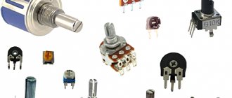
Elements can be wire or non-wire. The latter will perfectly perform their function in a high-frequency circuit; their appearance and manufacturing process are different. There are resistors for general use and special ones. The former do not exceed 10 megaohms, while the latter are capable of operating at voltages of 600 volts and higher. They also differ in appearance. In the photo below it is easy to see the difference and understand what the resistor looks like.
Difference in appearance and size
What does it consist of?
By winding the wire around a frame made of ceramic or pressed powder, you get a wirewound resistor. In this case, the wire itself must be made of nichrome, constantan or manganin. This will create a semiconductor with high resistivity.
Non-wire elements are made on a dielectric basis from conductive mixtures and films. They are divided into thin-layer and composite, but they all have increased accuracy and stability in operation.
The adjusting and tuning elements are a ring resistive plate along which the slider moves. It slides in a circle, changing the distance of the points on the resistive layer, as a result the resistance changes. You need to understand what a resistor does for a device.
What is it used for?
What is a resistor for? Using this part in an electrical circuit, you can limit the amount of current conducted; as a result of a correctly selected part, it is easy to obtain the required value. The higher the resistance, the lower the output current will be, provided the voltage is stable.
It’s easy to understand how resistors work; they can be used as a voltage-to-current converter and vice versa, in measuring devices they are used to divide voltage, and they can also reduce or completely eliminate radio interference.
Designation on diagrams
In Russia and Europe, the resistor in the diagram is indicated by a rectangle with dimensions of 4 * 10 mm. There are symbols to determine resistance values. The permanent element in the diagram is designated as follows:
Designations of permanent elements in the diagram
Variables, including tuning ones, as well as non-linear ones as follows:
Designations of variable conductors
Important! There is always an error in the resistance declared by the manufacturer; it is indicated using letters and numbers in percentage terms.
Characteristics and parameters
A resistor, like any other radio element, is characterized by various parameters that determine its properties. The main one, known even to “dummies,” is the nominal resistance. But few novice radio amateurs know that in addition to it, there are a number of other important characteristics.
The main parameters of the resistor include:
- Working resistance. The main parameter, the value of which indicates how much resistance the element has to the passage of current.
- Limit power dissipation. Shows what maximum energy a radio component can absorb without changing its other characteristics.
- Temperature coefficient. Depicted as a function and indicated in manufacturers' reference books. Characterizes the change in resistance value depending on temperature.
- Error tolerance. Indicates the percentage within which the resistance can vary depending on the declared value.
- Operating voltage. The amount that an element can withstand while maintaining proper performance.
- Excessive noise. This coefficient indicates how much distortion the signal receives after passing through the resistor.
- Moisture and heat resistance. They show how the influence of moisture and heat affects changes in the parameters of the element.
- Voltage factor. Takes into account the dependence of resistance on applied voltage.
- Parasitic component. Characterized by the value of capacitance and inductance.
At the same time, some characteristics may be insignificant, while others play a major role. This depends on the operating mode of the circuit in which it is used. For example, on the frequency of the signal. If the resistor operates at high frequencies, then due to the presence of foreign components, the resistance value may increase or decrease.
Types of resistors
Resistors come in three types:
- Constant - the resistance value of which does not change. It should be noted that small changes do occur due to temperature changes. But these changes are not significant, since they do not affect the operation of the circuit.
- Variables - their resistance varies within certain limits. For example, rheostats. When we turn a radio knob to change the sound or move a slider, we change the resistance of the circuit.
- Adjustable - change the value using a screw. This is rarely done to obtain the desired circuit parameters.
Classification of resistors
Resistors differ not only in their ability to adjust resistance. They can be made from different resistive materials, have different numbers of contacts, and have other features.
By type of resistive material
The elements can be wire, non-wire or metal foil. High-resistance wire is a feature of a wire element; alloys such as nichrome, constantan or nickel are used for its manufacture. Films with increased resistivity are the basis of non-wire elements. Metal foils use special foil. Now let's find out what resistors are made of.
Semiconductor design
Non-wire are divided into thin-layer and composite, the thickness of the former is measured in nanometers, and the latter in fractions of a millimeter. Thin-layers are divided into:
- metal oxide;
- metallized;
- borocarbons;
- metal-dielectric;
- carbonaceous.
Composite ones, in turn, are divided into volumetric and film. The latter can be with an organic or inorganic dielectric. To understand whether a resistor has polarity, you should know that their sides are identical.
By purpose resistance
Permanent and variable semiconductors also have some differences in characteristics. Permanent ones are divided into general and special purpose conductors. The latter may be:
- high frequency;
- high voltage;
- high-megaohm;
- precision.
Such parts are used in precision measuring instruments; they are particularly stable.
Variable resistors can be divided into trimming and adjusting. The latter can be with a linear or nonlinear functional characteristic.
By number of contacts
Depending on the purpose of the resistor, it may have one, two or more contacts. The contacts themselves are also different, for example, for SMD resistors it is a contact pad, for wire resistors it is a special wire composition. There are metal film resistors with quantum point contacts, and in variables they are moving.
Different number of contacts on elements
Other
Resistors differ in the shape and type of resistance, as well as in the nature of the dependence of the resistance value on voltage. The description of the dependence of a quantity can be linear or nonlinear. Using the element is simple, the capacity is indicated on the body, minus and plus are the same.
Resistors may or may not be sealed against moisture, and the housing may be varnished, vacuum sealed, sealed, pressed into plastic, or compounded. Nonlinear ones are divided into:
- varistors;
- magnetoresistors;
- photoresistors;
- posistors;
- strain gauges;
- thermistors.
They all perform their specific function, some change resistance based on temperature, others on voltage, and others on radiant energy.
How to maintain polarity when soldering a reed switch?
The reed switch has no polarity. The resistor does too. Therefore, he can solder them in any way he likes, as long as it is in series and in the gap between the desired I/O pin and VDD (power supply, which is taken from the same circuit). Also, in theory, there should be a high resistance resistor going from the I/O pin to GND to remove noise. But it depends where “there” is.
Let the reed switch break the positive wire
don't care how. they both stand in an OPEN WIRE OF THE SAME POLARITY
weird question. I don't care how
if you connect + - there will be a short circuit, if on the contrary there will be a short circuit XD
touch.otvet.mail.ru
Types of resistors
There are many types of resistors that are used in the electronics industry. Let's look at the main ones.
Fixed resistors
Constant resistors look something like this:
On the left we see a large green resistor that dissipates a lot of power. On the right is a small tiny SMD resistor that dissipates very little power, but still performs its function perfectly. You can read about how to determine the resistance of a resistor in the article marking resistors.
This is what a constant resistor looks like on electrical circuits:
Our domestic image of a resistor is depicted as a rectangle (on the left), and the overseas version (on the right), or as they say - bourgeois, is used in foreign radio circuits.
This is how power is marked on Soviet resistors:
Next, the power is marked using Roman numerals. V – 5 Watt, X – 10 Watt, L -50 Watt, etc.
What other types of resistors are there? Let's look at the most common ones:
20 watt glass with wire leads, 20 watt with mounting tabs, 30 watt in vitreous enamel, 5 watt and 20 watt with mounting tabs
1, 3, 5 watt ceramic; 5,10,25, 50 watt with conductive heat exchange
2, 1, 0.5, 0.25, 0.125 watt carbon structure; SMD resistors of standard sizes 2010, 1206, 0805, 0603,0402; SMD resistor assembly, 6,8,10 pin resistor assemblies for through-hole mounting, resistor in DIP package
Variable resistors
Variable resistors look like this:
On the diagrams they are indicated as follows:
Accordingly, domestic and foreign versions.
And here is their pinout (location of pins):
The variable resistor that controls the voltage is called a potentiometer, and the one that controls the current is called a rheostat. Here lies the principle of a voltage divider and a current divider, respectively. The difference between a potentiometer and a rheostat is in the connection diagram of the variable resistor itself. In a circuit with a rheostat, a variable resistor connects the middle and outer terminals.
Variable resistors whose resistance can only be changed using a screwdriver or hex wrench are called variable tuning resistors. They have special grooves for adjusting the resistance (marked with a red frame):
And this is how trimming resistors and their connection circuits in rheostat and potentiometer mode are designated.
Thermistors
Thermistors are resistors based on semiconductor materials. Their resistance depends sharply on the ambient temperature. There is such an important parameter of thermistors as TCR - thermal coefficient of resistance. Roughly speaking, this coefficient shows how much the resistance of the thermistor will change when the ambient temperature changes.
This coefficient can be either negative or positive. If the TCR is negative, then such a thermistor is called a thermistor, and if the TCR is positive, then such a thermistor is called a posistor. For thermistors, as the ambient temperature increases, the resistance decreases. For posistors, as the ambient temperature increases, the resistance also increases.
Since thermistors have a negative coefficient (NTC - Negative Temperature Coefficient - negative TCS), and posistors have a positive coefficient (RTS - Positive Temperature Coefficient - positive TCS), they will be designated accordingly in the diagrams.
Varistors
There is also a special class of resistors that sharply change their resistance as the voltage increases - these are varistors.
This property of varistors is widely used to protect against overvoltage in a circuit, as well as against pulsed voltage surges. Let’s say our voltage “jumped”. The varistor “snapped” the whole thing and immediately sharply changed the resistance downward. Since the resistance of the varistor has become very small, all electric current will immediately begin to flow through it, thereby protecting the main circuit of the radio-electronic device. In this case, the varistor takes all the power of the pulse onto itself and very often pays for it with its life, then it burns out completely
In the diagrams, varistors are designated as follows:
Photoresistors
Photoresistors are also very popular. They change their resistance when you shine light on them. For these purposes, you can use both sunlight and artificial light, for example, from a flashlight.
In the diagrams they are designated as follows:
Strain gauges
The principle of their operation is based on stretching thin printed conductors. When stretched they become even thinner. It's like pulling out chewing gum. The more you stretch it, the thinner it becomes. And as you know, the thinner the conductor, the greater the resistance it has.
In the diagrams, the strain gauge looks like this:
Here is an animation of the strain gauge in action, borrowed from Wikipedia.
Well, as you guessed, strain gauges are used in electronic scales, as well as in various sensors where any pressure or force is applied.
The principle of operation of a resistor in simple terms
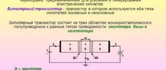
All electronic devices consist of radio components, which are divided into two large types: active and passive.
Active ones amplify electrical signals. A weak signal at the input controls a strong one at the output. In this case, the gain is greater than unity.
The resistor is a passive type of part whose gain is less than unity.
In Soviet times, resistors were called resistances. These days these parts are called resistors. This was done because all parts used in electronics have resistance. To avoid confusion, active resistances are called resistors.
All conductors have resistance, which is considered harmful, since it leads to heating of the element through which the current flows. In addition, electrical power is lost. The value of the resistor is useful. It heats up and produces heat. Heating stoves and lamps used in everyday life operate on this principle.
Thermal effect of electric current
When electric current passes through a conductor, it has a thermal effect—the conductor heats up. The degree of heating is determined by the amount of current and resistance in accordance with the Joule-Lenz law.
Q = I²*R*t, where Q is the amount of heat, I is the current strength, R is the resistance, t is time
Soldering irons and all kinds of heaters operate on this principle.
Concluding the first part of the article, the resistor in the electronic circuit also heats up to one degree or another.
Resistors can carry different currents, so they can dissipate different amounts of power.
Thermal power is dissipated in the form of radiation. The radiation intensity is determined, among other things, by the radiation surface area.
Therefore, in order to dissipate more power, a larger radiation surface is required, and, accordingly, larger resistor dimensions.
Operating principle of a variable resistor
Potentiometer circuit
By turning the knob, the length of the resistor changes, and as a result, the current strength. The figure shows a variable resistor with three terminals - a potentiometer. The resistance between ends 1 and 3 varies from 0 to maximum, depending on the position of the handle. The same picture occurs between ends 2 and 3, but in reverse. That is, if resistance 1 – 3 increases, 2 – 3 decreases. When a variable resistor has two ends, we have a rheostat.
The figure shows a rotary variable resistor. There are also sliders, where the slider moves in a straight line. By turning the knob, the resistance changes from zero to maximum. Potentiometers are widely used in audio equipment.
Potentiometer
Potentiometers are recessed into cylindrical and parallelepiped housings. Inside the housing there is a horseshoe-shaped resistive element. Along the axis of the part there is a metal handle, turning which changes the position of the current collector, which is located at the opposite end.
The current collector plate is securely pressed against the resistive element due to elastic force. It is made of steel or bronze. Voltage is applied to the extreme ends of the potentiometer. By rotating the handle, the current collector slides along the resistive element, changing the voltage between the extreme and middle ends.
The figure shows a wirewound potentiometer in which the resistive layer is made of wire. A high-resistance wire is wound around a horseshoe-shaped frame. The contact surface of the ring is then ground and polished. This is done to ensure a reliable connection between the slider and the conductive layer.
Non-wire potentiometers are also manufactured. In them, a resistive layer is applied to a ring-shaped or rectangular base made of insulating material.
Visual inspection
Violation of the normal operating mode causes overheating of the part, therefore, in most cases, the problematic element can be identified by its appearance. This can be either a change in the color of the case or its complete or partial destruction. In such cases, it is necessary to replace the burnt element.
Figure 4. A clear example of how a resistor can burn out
Pay attention to the photo above, the component clearly needs to be replaced, while the neighboring parts “2” and “3” may be working, but they need to be checked.
The operating principle of a trimmer resistor
After installing parts of an electronic device, its characteristics usually differ from the nominal ones. To fine-tune the performance of the device, trimming resistors are used. In principle, these are the same variable resistors, but separated into a separate group because they are structurally different from variable resistors. They don't have knobs that you can turn to change. Instead, there are holes for a slotted or straight screwdriver.
Trimmer resistor with cross slot
During operation of the device, after some time, its parameters change. To bring them to the nominal value, trimming resistors are used.
Depending on the type of slider movement, there are trimmer resistors with straight movement and circular movement.
To fine-tune the parameters of an electronic device, trimming resistors with a high number of revolutions are used. In them, the change in resistance from minimum to maximum is carried out in several revolutions or even tens of revolutions of the tuning shaft. In these resistors, the contact movement occurs using a worm gear.
which side to solder the resistor? which side is which?
The absolute majority of resistors are non-polar, problems arise when wiring variable resistors and photoresistors; the rest, as written above, makes no difference
A resistor is not a diode, it’s a bit of a problem to solder.
The resistor has leads or legs, so it needs to be soldered to them.
And yet there is a difference in how you solder the resistor. If the resistor is new, you need to bend the leads so that the markings are up and there is a small margin in height. All this will make possible repairs easier. It is useful to solder and tin the leads before installation.
Northern, through the compass!
touch.otvet.mail.ru
The principle of operation of a car heater resistor
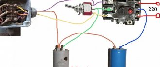
Car heater diagram
A regular VAZ stove has four speeds. As we can see from the figure, the rotation speed of the stove motor depends on the resistors. The resistor switch is the heater speed switch. In order for the air entering the cabin from the stove to be warm, the engine must be warmed up. Drivers often turn on the heater to cool the engine if it overheats.
If there is no need to heat the car interior (in warm weather), then air is pumped into the cabin directly, bypassing the heater radiator, through the heater filter. For this purpose, there is a special damper, which is switched from inside the car by the driver.
Knowing the connection diagram of the stove resistor, you can easily replace this resistance if it fails. You can do this yourself, rather than paying a lot of money at a car service center.
Properties in theory and practice
The main property of this radio component is resistance. Measured in ohms (ohms).
Let us first examine the concept of active resistance. It is so called because all materials have it (even superconductors, even if it is 0.00001 Ohm). And it is this that is fundamental for resistors.
What the theory says
In theory, a resistor has a constant resistance, which does not depend on external conditions (temperature, pressure, voltage, etc.).
The graph of current versus voltage is straightforward.
Under ideal and mathematical conditions, a resistor has only active resistance. There are nonlinear and linear resistors by type.
What really
In fact, all resistors have a non-linear dependence of current on voltage. That is, its resistance also depends on external conditions, specifically on temperature.
Of course, this dependence is not the same as for semiconductors, but it exists. And most importantly, this radio component has capacitance and inductance. In addition to active resistance, there is also reactive resistance.
Reactance differs from active resistance in that it passes electric current differently at different frequencies.
For example, for direct current the resistance is 200 Ohms, and if there are high inductance values, then at frequencies above 2 kHz, the resistance will already be 250 Ohms.
This is why resistors are made from different materials. They come in ceramic, carbon, wire and have different tolerances and errors. An SMD part has lower capacitance and inductance than a DIP part.
There are also special types of resistors with a more pronounced nonlinear current-voltage characteristic. If for ordinary resistors the current-voltage graph is slightly non-linear, then for this type of part it is avalanche-like.
Their resistance depends sharply on external conditions, not so. as usual:
- Thermistor. Increases or decreases resistance due to the influence of temperature;
- Varistor. Changes its properties depending on the applied voltage;
- Photoresistor. Resistance decreases when exposed to light;
- Strain gauge. When deformed (compression, mechanical stress), its resistance changes.
In addition, another feature of active resistance is the generation of heat when electric current passes. When electric current flows in a closed circuit, electrons strike atoms. And therefore heat is released. Heat is measured in power. It is calculated based on voltage and current.
One of the popular functions of resistors is to reduce voltage and limit current. For example, if a current of 0.25 A passes through a resistor and there is a voltage drop across it of 1 V, then the power that will be dissipated across it is 0.25 W.
Therefore, some parts change their resistance, even if they are not intended for this. These are already the properties of the material. And if the resistor is made of wire, then when heated it expands and its conductivity deteriorates. Therefore, parts have a tolerance, which is measured as a percentage.
And because of this, there are resistors with different power dissipation. You cannot put a 0.125 W resistor in place of a 1 W resistor. It will begin to heat up, crack, and turn black. And then it will burn. Because it is not designed for such power.
LED device
LEDs are semiconductor devices with an electron-hole junction that creates optical radiation when an electric current is passed through it in the forward direction.
The light emitted by an LED lies in a narrow range of the spectrum. In other words, its crystal initially emits a specific color (if we are talking about LEDs in the visible range) - in contrast to a lamp that emits a wider spectrum, where the desired color can only be obtained by using an external light filter. The emission range of an LED largely depends on the chemical composition of the semiconductors used.
Resistor markings.
The resistor designations on the diagrams vary depending on the country. In our country, you can understand where the resistor is marked by a rectangle marked in the form of inclined or vertical lines, V or X signs, with the letter “R” at the top of the rectangle. On foreign (American) circuits, the resistor is indicated by a solid line with several breaks.
The figure below shows the resistor markings:
Slanted lines indicate resistor power up to 1 W. Vertical lines and V and X (Roman numerals) indicate the resistor's power of several watts, according to the Roman numeral value.
Variable resistor.
A variable resistor is a resistor in which the electrical resistance between the moving contact and the terminals of the resistive element can be changed mechanically.
Variable resistors, also called rheostats or potentiometers, are designed to gradually regulate current and voltage.
The difference is that a rheostat regulates the current in an electrical circuit, and a potentiometer regulates the voltage. On radio circuits, variable resistors are designated by a rectangle with an arrow attached to their body.
In the diagrams, numbers 1 to 3 indicate the location of the resistor outputs.
You can adjust the resistance power of variable resistors by rotating a special knob. Those resistors in which the resistance of the resistor can be adjusted only with a screwdriver or a special hex key are called tuning variable resistors. They look like this:
LED Polarity
If turned on incorrectly, the LED may break. Therefore, it is important to be able to determine the polarity of a light source. Polarity is the ability to pass electric current in one direction.
Mono polarity can be determined in several ways:
- Visually. This is the easiest way. To find the plus and minus of a cylindrical diode with a glass bulb, you need to look inside. The cathode area will be larger than the anode area. If you can’t look inside, the polarity is determined by the contacts - the long leg corresponds to the positive electrode. SMD LEDs have markings indicating polarity. They are called a bevel or a key, which is aimed at the negative electrode. Small smds are marked with pictograms in the form of a triangle, the letter T or P. The corner or protrusion indicates the direction of the current - which means this pin is a minus. Also, some LEDs may have a mark that indicates polarity. It could be a dot, a ring strip.
- Using power connection. By applying a low voltage, you can check the polarity of the LED. To do this, you need a current source (battery, accumulator), to the contact of which an LED is applied, and a current-limiting resistor through which the connection occurs. The voltage needs to be increased and the LED should light up when turned on correctly.
- With the help of testers. The multimeter allows you to check the polarity in three ways. The first is in the resistance test position. When the red probe touches the anode and the black probe touches the cathode, a number other than 1 should light up on the display. Otherwise, the number 1 will light up on the screen. The second method is in the dial position. When the red probe touches the anode, the LED will light up. Otherwise he will not react. The third method is by installing an LED in the transistor socket. If a cathode is placed in hole C (collector), the LED will light up.
- According to technical documentation. Each LED has its own marking, which can be used to find information about the component. The polarity of the electrodes will also be indicated there.
The choice of polarity determination method depends on the situation and whether the user has the right tool.
Thermistors, varistors and photoresistors.
In addition to rheostats and potentiometers, there are other types of resistors: thermistors, varistors and photoresistors. This is interesting, but thermistors, in turn, are divided into thermistors and posistors. A posistor is a thermistor whose resistance increases with increasing ambient temperature. With thermistors, on the contrary, the higher the temperature around, the lower the resistance. This property is referred to as TCR - thermal coefficient of resistance.
Depending on the TKS (it is negative or positive), thermistors are designated on the diagram as follows:
The next special class of resistors are varistors. They change the resistance force depending on the voltage applied to them. In the picture below you can see what varistors look like
Knowing the properties of a varistor, you can guess that such a resistor protects the electrical circuit from overvoltage. In the diagrams, varistors are designated as follows:
Depending on the light intensity, another type of resistor changes its resistance - photoresistors. Moreover, it does not matter what the source of lighting is: artificial or natural. Their peculiarity is also that the current flows in them both in one and in the other direction, that is, they also say that photoresistors do not have a pn junction. Photoresistors look like this:
And the diagrams look like this:
Today it is impossible to manufacture a single, somewhat functional electronic device without resistors. They are used everywhere: from computers to security systems.
How to calculate power in a circuit
For circuits, knowledge about current strength and resistance is also required; without knowledge of these parameters, calculations will be impossible.
Thermal losses on the resistor are formed from the square of the current multiplied by the resistance: P = I² * R (the amount of heat on the resistor formula). It is relevant only when calculating a ready-made and known circuit; in all cases of preliminary calculation, the direct value of the current strength is used, and not its square. The value is indicated exclusively in Ohms; if values in kilo- or mega-ohms are used, then they must be rounded to the classic value of one unit of resistance - Ohm.
Circuit with serial connection of elements
Series connection means the fact that the same current value passes through all elements of the circuit. This means that the dissipation will be identical for all resistants. To calculate you need:
- Sum the values in all sections, that is: 200 Ohm + 100 Ohm + 51 Ohm + 39 Ohm = 390 Ohm. The current strength is calculated according to the law: I = U/R. Algebraically, the value is formed in the following form: I = 100 V / 390 Ohm = 0.256 A.
- Calculate parameter: P = 0.256² * 390 Ohm = 25.549
This is the answer to the question of how much thermal power will be released by resistor r1 in the circuit.
In this way, it becomes possible to calculate individual dispersion at each site indicated in the diagram.
Symbols on diagrams
On diagrams in Europe and the CIS it is indicated by a rectangle and a Latin letter R. According to GOST, on domestic diagrams the resistance rating is not indicated, but only the part number (R). However, if there is a number below the part image, such as 120, it will default to read 120 ohms.
The table contains examples of part designations.
| Basic designation |
| 0.125 W |
| 0.25 W |
| 0.5 W |
| 1 W |
| 2 W |
| 5 W |
| Variable |
| Trimmer |
How to measure the resistance of a resistor
Any resistor has resistance. For those who don’t know what resistance is and how it is measured, read this article as a matter of urgency. Resistance is measured in Ohms. But how do we find out the resistance of the resistor? There are direct and indirect methods.
The direct method is the simplest. We need to take a multimeter and simply measure the resistance of the resistor. Let's take a look at what this all looks like. I take a multimeter, set the knob to measure resistance and touch the resistor terminals.
Resistance measurement
I took a 1 kOhm resistor. He showed me 976 Ohms, which in principle is also normal, since such resistors always have some error.
The indirect measurement method is that we will calculate the resistance of the resistor through Ohm's law.
resistance formula through Ohm's law
Therefore, to find out the resistance of the resistor, we need to divide the voltage at the ends of the resistor by the current that flows through the resistor. It's quite simple!
Let's say I want to know the resistance of a light bulb's filament when it emits light. I think some of you are aware that the resistance of a cold tungsten filament and a hot one are completely different resistances. I can’t measure a red-hot tungsten filament of an incandescent lamp with a multimeter in resistance measurement mode, right? Therefore, this formula comes in handy for us.
Let's find out by experience. I have a laboratory power supply that immediately shows the voltage and current that flows through the load. I take a lamp, set the voltage on the power supply, which is written on the lamp itself, and connect it to the terminals of the power supply.
Incandescent lamp current consumption
So, it turns out that the voltage at the lamp terminals is now 12 Volts, and the current that flows in the circuit, and therefore through the lamp, is 0.71 Ampere.
We find that the resistance of the hot filament of the lamp in this case is.
Checking the resistor for suitability with a multimeter
Let's consider such questions as the polarity of the resistor, how to determine the resistor on the board, how to measure it with a multimeter, when you need to connect a soldering iron, how alternating current affects measurements.
- Connect the test leads to the digital multimeter. Connect the black probe to the com (common) port and the red probe to the port marked with the Ohm symbol, which looks like an inverted horseshoe. For those of you who remember Greek, the symbol for Om is the Greek letter Omega. This digital multimeter has banana jack port connectors. Other digital multimeters may have screw terminals or BNC connectors.
- Connect alligator clips to each resistor terminal. The most common resistors have a 4-color stripe. The first two colors indicate the values, the 3rd bar indicates the multiplier, and the 4th bar indicates the % tolerance of the resistor value. The resistor pictured is red (2), purple (7), orange (x 1000) and gold (5%). This resistor should theoretically have a value of 2700 ohms with a tolerance of 5% of the value. The lower the tolerance value, the better the resistor.
- Set the multimeter's digital dial to Ohms (Omega). Some less expensive digital multimeters have ohm settings with multipliers (x 100, x 1000, etc.). The DMM shown is autoranging, so the multiplier will be displayed on the screen along with the readings, which will allow you to measure the data.
- Take readings from your digital multimeter. The test pictured shows a value of 27.02 kΩ. Therefore, the resistor value is 2702 ohms. This value is within 5% deviation from 2700 ohms. The resistor is ready for your project.
- Take readings from your digital multimeter. This resistor is color coded green, brown, gold and should therefore have a value of 510 ohms. The digital multimeter shows 509 ohms. The DMM test shows a good resistor.
Oscilloscope S1-94 - characteristics, electrical diagram
Checking the resistance of a fixed resistor
One of the important measurements you can take with a multimeter is resistance measurement. Not only can they be made to test the accuracy of a resistor or verify that it is working correctly, but resistance measurements may be required in many other scenarios as well. For proper quality, the multimeter must be configured correctly
In fact, there are many cases where measuring resistance is of great interest and importance. In all these cases, a multimeter is the ideal test equipment to measure resistance in order to properly desolder the board.
Series and parallel connection of resistors
All of the above resistors can be connected in parallel or in series. In a parallel connection, the resistor leads are connected at common points.
In this case, to find out the total resistance of all resistors in the circuit, it will be enough to use the formula, where the resistance between points A and B (RAB) is the same R total:
When connected in series, the resistor values are simply summed up stupidly
In this case
Good video on the topic
The thermal power of 10 W is released on the external circuit resistor of the battery
This parameter and condition are relevant when three batteries are connected in series. If an external circuit with a battery is connected to the ends, then for each subsequent battery the value will increase by 2 times. But since power depends on voltage through current, for the third battery the increase in power will be 25%. Thermal losses will be 26.9 W.
Using the information presented in this article, you can independently and quickly select the necessary electrical circuit elements in an electrical appliance for replacement. To this end, there are currently many electronics stores that will satisfy the needs of the most demanding customers.
This article can be used as a specific guide to the selection of resistors not only for household electrical appliances, but also for industrial installations.
Inclusion types and usage examples
The main types of connection are serial and parallel connections.
Series resistance is calculated simply. It's enough to put everything together.
In a series connection, the voltage is distributed across the resistors according to their resistances.
This is Kirchhoff's second rule. For example, the voltage is 12 V, and a pair of resistors are 1 kOhm each.
Accordingly, each of them has 6 V. This is a simple example of a voltage divider. Here a couple of parts share the voltage and through this the required voltage can be obtained.
However, if you want to use a voltage divider to power a circuit, you must remember that you need to match the resistances. In this circuit the resistance is 1 kOhm. If you connect a load less than this resistance to it, then it will not receive the full voltage at its terminals. Therefore, all circuits with voltage dividers must be calculated and coordinated with each other.
Let's look at the example of a transistor amplifier.
Here R1 and R2 form a voltage divider, they act as a voltage divider. A current flows between these two resistors and the base of the transistor, which turns on the transistor.
This is necessary for it to work without distortion.
Parallel connection
When connecting radio components in parallel, the overall resistance of the circuit decreases. If two 1 kOhm resistors are connected in parallel, then the total will be less than 0.5 kOhm, i.e. The circuit resistance (equivalent) is equal to half the smallest.
In such a connection, Kirchhoff's first rule is observed. A current of 1 A is sent to the connection point, and at the node it diverges into two directions of 0.5 A each.
Calculation formulas
For two resistors:
For more:
For current, a parallel connection is like a second road or bypass. This type of connection is also called bypassing. An example is an ammeter. To increase its reading scale, it is enough to connect another shunt resistor in parallel with the resistor.
Its resistance is calculated by the formula:
Equivalent connection
In the amplifier circuit, a pair of resistor R3 and capacitor C2 is connected to the emitter of transistor VT1.
In this case, VT1 and R3 are connected in series to each other. Why is this necessary? When the amplifier is running, the transistor begins to heat up and its resistance decreases. R3, as in the case of the LED, prevents the transistor from overheating. It balances the total resistance so that the transistor does not distort the signal. This is called thermal stabilization mode.
And capacitor C2 is connected to R3 in parallel. And this is necessary so that during normal operation of the amplifier, the alternating signal passes through without loss. This is how a parallel filter works.
If there was only one R3, then the amplifier's power would be much less due to the fact that it takes the AC voltage onto itself. A capacitor transmits without loss, but does not transmit DC voltage.
Features of using resistors in circuits
Resistors can be connected in series or in parallel.
[Resistance of series connected resistors
] = [
Resistance R1
] + [
Resistance R2
]
[Resistance of parallel connected resistors
] = 1 / (1 / [
Resistance R1
] + 1 / [
Resistance R2
])
The figure shows typical resistor circuits. (A) – 'Current to voltage converter'. The voltage across a resistor is equal to its resistance times the current. (B) – 'Voltage to current converter'. The current through a resistor is equal to the voltage across it divided by its resistance. (B), (D) – Voltage divider. The voltage at the divider output is equal to the input voltage multiplied by the resistance of the lower resistor, divided by the sum of the resistances of both resistors. Circuit (D) is an adjustable divider formed by two halves of a variable resistor. It can be used to mechanically regulate the output voltage level. (D) – current source. A resistor works well as a current source if a fixed voltage is applied to it. Yes, in the diagram shown, both the upper and lower resistors are current sources, and not at all a voltage divider, as it might seem at first glance. The fact is that the voltage drop between the base and emitter of the transistor depends little on the current. So both the lower resistor and the upper one operate under fixed voltage conditions. The voltage across the lower resistor is equal to the base-emitter saturation voltage, and the voltage across the top resistor is equal to the supply voltage minus the base-emitter saturation voltage.
(read more...) :: (to the beginning of the article)
Contents :: SearchSafety :: Help
Unfortunately, errors are periodically found in articles; they are corrected, articles are supplemented, developed, and new ones are prepared. Subscribe to the news to stay informed.
If something is unclear, be sure to ask!Ask a question. Discussion of the article.
More articles
Checking resistors, capacitors, diodes, rectifier bridges. About...How to check a resistor, capacitor, diode, bridge. Test method….
Practice of electronic circuit design. Self-instruction manual for electronics….The art of device development. Element base of radio electronics. Typical schemes...
Voltage divider. Scheme, calculation, formula. Calculate. Application. O...Voltage divider. Online payment. Application using an oscilloscope as an example...
Linear series compensating voltage stabilizer continuous...How to design and calculate a continuous voltage stabilizer in...
Step-down switching power supply. Voltage feedback. ...Step 4. Method for calculating error amplifier compensation circuits. How to use field t...
Switching time of the field effect transistor. Capacitance gate - drain, source.... Switching of the field-effect transistor. Input containers. Built-in diode. ...
Dynamic, differential resistance. Nonlinear elements. Pon...The concept of differential, dynamic resistance. Definition. Properties….
Low Dropout Adjustable Series Regulator...How to Design and Calculate a Low Dropout Adjustable Series Regulator...