A lighting control system based on pulse relays can no longer be called some kind of know-how.
She appeared a very long time ago. However, the widespread practice of introducing and using bistable relays, as they are also called scientifically, instead of the old time-tested pass-through switches, is becoming increasingly widespread right now.
Of course, there are more modern devices based on control via a Wi-Fi signal or connected to a PLC, but impulse switches (blocking relays) are more affordable for a wide range of ordinary users.
On average, their price ranges from 1000 - 1500 rubles per piece, depending on the manufacturer and functionality (built-in timer, central control function, etc.)
They are also more repairable. If one relay fails, only one lighting zone will stop working, and the light will not go out in the whole house, as will happen with a PLC.
Let's look at how it all works, what circuits it is connected to, and try to figure out whether it is better or worse than pass-through switches.
Impulse relays or pass-through switches
In long corridors, on stairs when going from the first to the second floor, in bedrooms, it is very convenient to turn on the light at the entrance, and turn it off in a completely different place (at the exit or near the bed).
In such cases, electricians recommend installing pass-through (flight) and cross switches.
What is the significant difference between them and impulse relays? And why does everyone refuse switches?
What does the connection diagram look like at the checkpoints? As a rule, power is first supplied to the branch box under the ceiling, and then from it to the switches themselves. For installation, a three-core cable VVGng-Ls 3*1.5mm2 is used.
The more switches you install, the more wires you will need.
When installing pass-through two-key switches, you already have 6 contacts, wires need to be connected to each of them.
Would you like to try connecting such a bundle correctly in a junction box? Not every electrician can immediately figure out such a connection diagram.
In this case, each of the switches passes directly through itself the entire load current. This means that during switching or a short circuit, contact burnout is quite possible.
Another feature of pass-throughs is the absence of a fixed key position. You cannot understand from its state whether the switch is on or off, as is done on a single-keyboard.
This will directly depend on other “brothers” collected in one chain. Which is not always convenient and takes some getting used to.
Operating principle
Table of degrees of protection
The main function of the RF is the formation of a time delay for switching control groups of contacts. The implementation of the delay depends on the design features of the device. There are many varieties of RV. From a functional point of view, they are pneumatic, motor, electromagnetic, electronic, as well as clockwork devices. They differ in parameters, appearance and installation method, and have the following technical characteristics:
- maximum switching current;
- rated switching voltage;
- type of contacts, their number;
- wear resistance (estimated number of inclusions);
- IP protection degree.
Electronic timers indicate the rated supply voltage and power consumption. As well as the period for storing programmed data in memory in the event of a power failure. The presence of an information screen and control system makes it possible to support several tasks simultaneously.
Devices are divided into devices with a switch-off or switch-on delay. Many relays have two options at once, changing the type of switching. The operating algorithm is as follows:
- During startup, the contact group is activated - the contacts are closed for the relay with a turn-off delay.
- The time delay mechanism is cocked.
- After the programmed interval has expired, the contact group changes order.
The on-delay relay works in a similar way. In cyclic type devices, a given sequence is repeated many times.
Why only push-button ones?
When using pulse relays, other types of switches are used - push-button, bell or push-type.
Please note that simple single-key or two-key keyboards will not work here.
With rare exceptions, for example for the Meander RIO-2 relay. But more on that later.
Based on this fact, a signal cannot be applied to pulse relays for too long, otherwise its coil will burn out. Some manufacturers warn that the continuous signal time on their models should be no more than 1 minute.
And some children really like to play with such buttons, after which they fail.
Push-button switches resemble ordinary ones in appearance, only inside their design there is a return spring, which after each press returns the key and contact to its original position.
There are also two-key buttons in one housing.
They will come in handy when you want to connect general lighting in the kitchen from one relay and at the same time illumination of the work area of the countertop.
Or in the hall - a chandelier and lighting around the perimeter, plus a separate sconce.
Many people use spring-loaded buttons for doorbells instead of special switches.
What to look for when purchasing
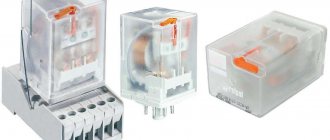
Various relay models
To select the appropriate model, you should be guided by the basic parameters of the device. Various models can be connected to a household network of 220 V, as well as to reduced control networks of 12, 42 and 127 V.
The contact capacity without overheating depends on the permissible load current. Where conditions do not allow contact switching due to explosion hazard, contactless devices must be installed.
Indicators of protection from moisture and temperature conditions determine the acceptable parameters of the operating environment. For correct operation of the relay, you should pay attention to the following nuances:
- preference should be given to devices with a wide range of time settings;
- the control panel should be simple and understandable;
- The display picture is clear and bright;
- numbers and icons are clearly visible and easy to read.
A simple programming language and the ability to transition from outdated systems based on relay-contactor circuits to microprocessor-based devices have allowed programmable relays to take their rightful place in the market of new automation devices.
Comparison of circuits using pass-through switches and pulse relays
The most important advantage of all these relays is that the buttons are connected to each other in parallel and a two-wire wire is enough for this.
Regardless of how many buttons you use - two, three, four, etc.
This significantly saves cable costs and simplifies lighting connections.
Visually compare the diagram and number of wires in the same room when installing pass-through switches and impulse relays.
Scheme on pass-through switches
Scheme on a pulse relay
As you can see, in the second case there is at least double savings (two-core cable instead of four-core, fewer connections, more free space in junction boxes). The functionality of the lighting in the room was not affected at all by this.
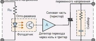
Control driver circuit for relays
Specifications:
- Driver power supply – 12 V at 40 mA
- Relay output – 5 A at 230 V
- Input Control – 2-15 VDC
- LED indicator shows relay status
- Board dimensions 27 x 70 mm
This is a single channel relay driver suitable for a variety of projects. A very simple and convenient way to interact with a relay to switch powerful consumers, which itself is controlled by weak current and voltage.
How to connect a pulse relay
To correctly connect a pulse relay, you need to understand what contacts it has and what they are responsible for.
Typically this is:
- two contacts per power coil A1-A2
On one of them, phase or zero constantly arrives, and on the other, an impulse is given after pressing the button.
- power contacts 1-2, 3-4, etc.
Passing through them, the current flows to the lamp.
Here is the simplest diagram for connecting one pulse relay to a group of push-button switches.
Scheme No. 1
Please note that in a pulse relay the load does not pass through the button at all. By pressing it, you just give an impulse to the coil, which closes the power contact.
In some models, a control pulse can be supplied both through the phase conductor and through the neutral conductor.
Imagine that a significant and extensive part of the electrical wiring in your house will not even be constantly energized, as is the case with conventional light switches. How much this will improve fire and electrical safety!
Some varieties have several contacts at once. You can connect two, three or more lighting groups from them.
Passing the entire load through the relay means that burning or burnout of the contacts on the buttons is virtually impossible. Many, rejoicing at this circumstance, boldly lower the cross-section of the lighting lines to 0.5mm2 or 0.75mm2. Or they simply “throw away” the twisted pair cable.
However, do not forget about the rules, which clearly state that all group lines to lamps in residential premises must be carried out with conductors with a cross-section of at least 1.5 mm2.
Please note that all relays (group or single) must be connected after the machine.
He protects:
- reel
- control cable
- the lamp itself
Without it, in the event of a short circuit, your electrical wiring will simply burn out.
The relay itself does not protect against overloads or short circuits.
Therefore, when assembling the circuit in the panel, you seem to “hang” one or more pulse relays on each lighting circuit breaker.
Other features
Time relay screen and control panel
Modern control systems have a variety of capabilities. On some models, additional programmable relay functions are displayed in three main and two mixed modes, which are designated as follows:
- H – weekly timer;
- U – voltage relay;
- F – photo relay;
- HU – weekly timer with controlled voltage;
- FU – photo relay with voltage control.
The weekly timer automatically performs an important daily function. For example, optimizing the parameters of a greenhouse or hatchery. Can control the operation of fountain devices and advertising structures.
Relay U provides protection of electrical equipment from possible fluctuations in the mains voltage. The connected device displays its actual value on the display.
If the value is within the specified limits, the load is turned on. When the voltage goes beyond the upper or lower threshold, the load is not connected.
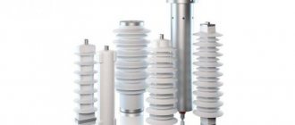
Photo relay for street lighting
Photo relay is the optimal option for programmable operation of lighting fixtures. It can be used both in everyday life and to control the lighting of various structures, lighting of garden and park areas, streets, and other public places.
There are also devices that combine the functions of a timer, photo relay and voltage relay. The non-volatile memory of such a device allows you to save programmed parameters not only during voltage surges, but even during power outages. Typically, the permissible load current for the device relay is up to 16 amperes. If the operating current is higher, the equipment is equipped with a magnetic starter or contactor.
The listed devices are designed to switch the load according to a set time, control voltage and disconnect consumers in case of significant fluctuations in the electrical network. Moreover, after the parameters are restored, they are automatically turned on. The set illumination level is switched and other programmable actions are performed.
Centralized lighting control with one button
On models with so-called central or centralized control, in addition to the above, there are additional ON and OFF terminals.
When voltage is applied to them, the relay is forced to either turn off (OFF) or turn on (ON).
They are used when assembling a circuit with a master button or master switch. That is, when leaving the house, with just one button you can centrally turn off the lights on all floors and in all rooms.
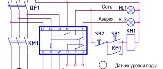
Here is a circuit assembled into several group lamps connected from different impulse relays. Please note that in this case all relays must be centrally controlled, otherwise the circuit will not work.
Scheme No. 2 - with central control
For ABB pulse generators, the central control unit can be purchased separately and connected to the left side of the E290 relay.
Just be extremely careful when assembling such a control circuit in a three-phase 380V switchboard.
If there is a three-phase system, some lighting groups are powered from different phases in order to evenly distribute the load.
In this case, it is impossible to connect all the OFF and ON contacts on the switches with jumpers, as is often done in single-phase panels. You will have to transfer all control circuits to a separate machine and it is from it that you will supply the phase of the same name to turn on and off all pulse relays simultaneously.
And then, this is possible when using electromechanical models. For electronic ones, you will have to decouple through intermediate relays.
What are timers, pause relays, delays
Let’s make a reservation right away: homemade auto-timers adjust the delay from a few seconds to 10–15 minutes. There are schemes only for incl. and for on/off load, as well as for activation at certain times of the day. But their delay range and options are limited; there is no function of periodically operating independently several times and adjusting the intervals between such cycles, like in factory outlet devices. However, the homemade capabilities (there are also ready-made similar simple modules on sale) are enough to activate garage ventilation, lighting in the pantry and similar not too demanding operations.
A temporary relay (timer, pause, delay relay) is an automatic release that is triggered at the moment set by the user, turning on/off (closing/opening contacts) of an electrical appliance. The timer is extremely practical in situations where the user needs the device to be activated or deactivated while he is in another location. Also, such a unit will help out in ordinary everyday situations, for example, it will protect you when you forget to turn off/on the equipment.
Thus, the temporary relay will eliminate situations where you left an electrical appliance on, forgot to turn it off, and, accordingly, it burned out or, even worse, caused a fire. By turning on the timer, you can go about your business without worrying about having to return at a certain time to service the equipment. The system is automated, the unit itself will turn off when the set period on the release has expired.
Where is it used?
Many people are familiar with the clicking sounds in Soviet washing machines, when large graduated selectors set a certain delay before turning on/off. This is a vivid example of this device: for example, they set it to work for 10–15 minutes, the drum spun for this time, then, when the clock inside reached zero, the washing machine turned itself off.
Manufacturers always install temporary relays in microwave ovens, electric ovens, electric water heaters, and automatic watering systems. At the same time, many devices do not have it, for example, lighting, ventilation (hood), then you can buy an additional timer. In its simplest form, it looks like a small rectangular block with time selectors and a plug for a regular socket (“daily” timer sockets) into which it is inserted. Then the power cable plug of the device being serviced is inserted into it, and the delay time is adjusted using the controls on the body. There are also standard sizes for placement by connecting to a line (with wires, wiring, for switchboards), for integration inside devices.
Device, types, features
Mostly timers in factory electrical appliances with trip units are based on a microcontroller, which often also controls all operating modes of the automated device where they are installed. The described combination of functions is cheaper for the manufacturer, since there is no need to manufacture separate microcircuits.
We will describe the simplest time delay relay circuits, only with an on/off option. and selecting a time pause in a small range (up to 15–20 minutes):
- for low-voltage power supply (5–14 V) - on transistors;
- on diodes - for power supply directly from a 220 Volt network;
- on microcircuits (NE555, TL431).
There are special factory modules, they can be bought on online sites (Aliexpress, similar and specialized resources), on radio markets, in special stores. Completely handicraft products are created according to similar schemes, mainly for simple tasks: elementary disengagement/coupling of contacts at a certain, specified point in time, while the delay range is small from seconds to 15–20 minutes.
Relay operation in non-standard situations
Many people wonder what will happen to the relay when the voltage in the house disappears and then reappears? Wouldn't all the lights turn on at once in this case? No, that won't happen.
However, the pin position status will vary depending on the specific model. Whether they have memory or not. If the memory is present, the previously turned on lights will light up again. Where there is no memory, the contacts will simply open.
What happens if two people press two buttons at the same time? This will be perceived as a one-time click. That is, the light will either light up or go out, depending on its previous position.
The pulse relay for installation in an electrical panel has the form factor of a modular contactor and is mounted on a DIN rail. The rated current of most models is 10-16A.
This is quite enough to organize lighting in an apartment or country house.
If you want to connect a more powerful load, then you will have to use a starter in the circuit, or choose models with higher currents.
The principle of operation of turn signals
Turn signals (direction indicators) are an essential part of the lighting equipment of any vehicle. On each vehicle they must be installed on both sides, front and rear (on trailers - only the rear) and are orange lights (in some countries red is allowed). Before starting the maneuver (the exact distance or time is not regulated by traffic regulations), the driver must turn on these lights on the side in which the turn will be made (in addition to the function of indicating a change in direction of movement, the turning lights provide an emergency signal).
The lamps should operate in flashing mode. This requirement is related to the peculiarities of human perception - we better notice not the intensity (brightness) of the signal, but its change. Therefore, a flashing flashlight quickly attracts attention, even if it is visible in peripheral vision. In addition, it is more difficult to confuse it with marker lights or other lighting equipment. Intermittent lighting in the most modern cars is provided using electronic units that include other operating functions. In machines developed in previous years (and they are the majority), the blinking function is provided by relay interrupters.
Pulse relay for installation in a distribution box
In addition to panel-mounted options, there are also mounted ones, for installation behind a suspended ceiling or directly into a distribution box.
With their help, you can organize the switching of lighting in your apartment from single-key switches to pulse switches. You replace the switches in the wiring boxes with buttons and switch the wires in the junction box.
This is what this diagram looks like when connecting a pulse relay directly in the distribution box under the ceiling.
Scheme No. 3
In this case, little changes in your electrical panel, and you get an excellent lighting control option, similar to pass-through switches.
When connecting several lamps at once from a standard impulse switch in a switchboard room, rather than just one light bulb, be sure to install a cross-module or terminal blocks.
It is unlikely that it will be possible to run two or three cables per relay (the limitation on the thickness of the wire will not allow it). You'll have to scatter them across different pads.
Advantages of a time relay
Time relay saves energy
Analogue and digital time relays are very convenient for controlling executive circuits of various household and industrial devices.
The on and off relay has a number of positive factors:
- optimizes the operation of household electrical and pumping appliances;
- saving energy resources when connecting a smart home system;
- switching of production equipment, mechanisms and other devices;
- settings allow you to select a mode that is convenient for an individual user;
- it is possible to set cyclic shutdown and on;
- A sound signal notifies you when the device is triggered.
In everyday life, a timer is used to operate a fan, refrigerator, air conditioner, and optimize lighting. The device can be used in educational organizations, workshops and schools, for example, to make a bell. Farms install special artificial light for the growth and development of animals. In production, various machines and mechanisms are switched on and off using relays. In agriculture, the relay controls irrigation and watering systems, pumping stations and ventilation units.
Types of pulse relays
What other types of pulse relays exist? For example, there is a time delay function.
It can be used to delay both when the light is turned on and when it is turned off. You leave your own cottage in the evening and press a special button in the house.
This gives you time to calmly walk along the illuminated paths to the gate and only after that the light will automatically turn off.
This method does not even require the installation of separate switches on the street.
You can also connect an exhaust fan in the bathroom to such relays. When leaving the bathroom, you press the button, and the fan continues to run for the period of time you set.
Switching on from different places using relays and limit switches
At the request of reader Zoltan, I quickly sketched out a circuit that turns on and off two groups of lighting on the street and in the garage. In this case, pushbuttons, limit buttons and relays are used.
Scheme for turning on the light through the end buttons, Start, Stop buttons and relays
I took inspiration from here:
Algorithm and discussion of the scheme in the comments, starting January 16.
By January 26, after several intermediate options, the following scheme was born:
Lighting circuit on a relay with a motion sensor, limit switch and time relay
And then the author of the video sent Zoltan his diagram, here it is!
Automation circuit for turning on lights from different places
Specifications
In accordance with clause 2.1. GOST 16121-86 parameters of pulse relays must comply with the technical specifications and standards on the basis of which they are manufactured. The most relevant for the operation of bistable switches are:
- the number of push-button switches that can be connected together with a certain type of lamp;
- limits of permissible voltage for switching;
- maximum current load permissible for switching;
- permissible number or power of light bulbs of a certain type;
- overall dimensions must correspond to passport data in accordance with clause 2.2.1 of GOST 16121-86
Fig.7. Example of overall dimensions of a pulse relay
- signal time and response delay;
- mechanical and electrical strength of structural elements;
- wear resistance by number of cycles;
- Climatic performance.
Some of this data can be found on the body of the pulse relay (see example in Figure 8), others only in the device passport.
Rice. 8. Relay characteristics
10 V devices
10 V relays are manufactured for making contactors. Resistors for devices are suitable of an adjustable type with an overload of 2 A. If we talk about simple modifications, then the coil can be safely used with a lining. It should also be noted that only two capacitors are required to assemble the relay.
The conductivity of the elements must be at least 5 microns. If the rated voltage increases significantly, it is recommended to check the resistance. The expanders of the modifications are of the wave type. The negative resistance of the elements reaches a maximum of 55 Ohms. In some cases, phase resistors are used. They have a low overload parameter, but they cope well with impulse noise.
Purpose of switches
An electromechanical relay is designed to connect a load to a circuit when a signal is applied to the contacts. Such a switch is called a pulse switch because it turns on when a corresponding signal is sent to the control input. The automation remembers the position of the contacts even when disconnected from the network and then, when power is restored, the device does not change its state until new control signals are received.
Today, such relays are used in electrical engineering, devices responsible for lighting control, power equipment and powerful power supplies. The switch may differ in its power, design and purpose. By correctly selecting and properly planning a circuit with pulse relays, it will be possible to ensure the operation of devices in a fully automatic mode, significantly simplifying their operation.
Model with microcontroller
Devices with microcontrollers are very common. They are suitable for pushbutton switches. The devices are also actively used in switches. Experts recommend using only capacitive resistors for assembly. In total, the relay will require three capacitors. The rated voltage is on average 24 V. With a conductivity of 2 μ, the resistor should produce an overload of 10 A.
The modulator for relays can be used as a line type. As a rule, modifications with three outputs are produced. The bistable relay (microcontroller) is controlled by a switch. It is also worth noting that there are devices with wired stabilizers. The resistance value of the elements should not exceed 45 Ohms.