LEDs have been used in electrical engineering for quite some time. But if previously they were used exclusively as various indicators, today the scope of application of these elements has expanded significantly.
Using infrared diodes, signals are transmitted from remote controls and all kinds of sensors; they are also used in surveillance cameras, control equipment and other devices.
Another variety - super-bright elements, having finally learned to truly glow, are quite confidently crowding out traditional lighting sources - incandescent lamps and even more advanced and economical fluorescent lamps.
It’s unlikely that anyone these days has not heard of LED strips (for plants, for example), and almost everyone has a flashlight with this type of light bulb. One way or another, LEDs are being used more and more widely, and therefore we are increasingly faced with the need (when trying to find out the reason for the breakdown of a particular device) to check their performance.
Next, we will talk about several ways to solve this problem easily and professionally.
Super bright
Testing yellow, blue and white LEDs used as lighting sources and called super-bright LEDs is not particularly difficult. To do this, it is enough to connect the element’s terminals to a power source with a voltage of 3 to 4.2 V (no more!).
As such a source, it is most convenient to use a pair of one-and-a-half-volt batteries connected in series. But the fact of the matter is that they are not always at hand.
Is it possible to carry out the test using a conventional multimeter, which every radio amateur has, especially since modern versions of this device provide a special mode for checking diodes?
It turns out there is such a possibility. Although the mentioned mode, due to insufficient power supply, will not help in this case. Instead, we will use the mode for measuring transistor parameters , which is also provided in every modern digital multimeter model.
To study transistors, the tester is equipped with a special connector to which the element leads are connected. It is labeled with the letters PHP. The cathode of the ultra-bright LED (this is the shortest pin) must be connected instead of the collector (position “C” on the connector), and the anode - instead of the emitter (position “E”). If the element is valid, it will begin to glow, and the position of the measurement mode switch in this case does not matter.
In most cases, the lighting element is part of the LED circuit and it will not be possible to plug it directly into the PHP connector without unsoldering. It is not possible to check it using probes, since they cannot be connected to the connector.
The problem can be solved by making a simple design consisting of an adapter and probes connected to it from an old or broken multimeter.
How to make probes with an adapter for a PHP connector
We need very little:
- two unnecessary probes (the plugs must be cut off);
- a small fragment of double-sided textolite;
- a pair of metal clips;
- SMD LED (necessary for ease of use, but the device will work without it).
A paper clip should be soldered to the textolite plate on each side, having first bent their ends 180 degrees. The result will be something like an electric plug.
The thickness of the PCB fragment should be such that the distance between the pins of the “plug” corresponds to the distance between the inputs “C” and “E” on the PHP connector. That's all, the adapter is ready. All that remains is to solder the wires from the probes to it (again on both sides).
It is better to place the textolite between the paper clips asymmetrically. This will make it easier to understand which side the adapter should be plugged into the transistor connector of the multimeter, so as not to confuse the polarity.
The design can be supplemented with an SMD type LED, which will serve as an indicator.
How to make a dipstick with your own hands
If you don't have standard probes to sacrifice, you can use homemade ones instead. To make them you will need:
- a pair of needles;
- tinned wire with a diameter of 0.2 mm (removed from a stranded wire).
The wire should be wound around the needle so that its turns fit snugly against each other, and then soldered. It is very convenient to use nickel-plated needles for this purpose , then soldering is done as easily and quickly as possible. Often such a probe provides better contact than a standard one.
Algorithm for troubleshooting an LED lamp driver or Hercule Poirot resting
Recently, a friend asked me to help with a problem. He is developing LED lamps, selling them along the way. He has accumulated a number of lamps that are not working correctly. Outwardly, this is expressed as follows: when turned on, the lamp flashes for a short time (less than a second), goes out for a second, and so repeats endlessly. He gave me three such lamps to study, I solved the problem, the fault turned out to be very interesting (just in the style of Hercule Poirot) and I want to tell you about the way to find the fault. The LED lamp looks like this:
Fig 1. Appearance of a disassembled LED lamp
The developer has used an interesting solution - the heat from the operating LEDs is taken by a heat pipe and transferred to a classic aluminum radiator. According to the author, this solution allows for the correct thermal conditions for LEDs, minimizing thermal degradation and ensuring the longest possible service life of the diodes. At the same time, the service life of the diode power driver increases, since the driver board is removed from the thermal circuit and the board temperature does not exceed 50 degrees Celsius.
This solution - to separate the functional zones of light emission, heat removal and power current generation - made it possible to obtain high performance characteristics of the lamp in terms of reliability, durability and maintainability. The disadvantage of such lamps, oddly enough, directly follows from its advantages - manufacturers do not need a durable lamp :). Does everyone remember the story about the conspiracy among incandescent lamp manufacturers about the maximum service life of 1000 hours?
Well, I can’t help but note the characteristic appearance of the product. My “state control” (wife) did not allow me to put these lamps in the chandelier where they are visible.
Let's return to the driver problems.
This is what the driver board looks like:
Fig 2. Appearance of the LED driver board from the surface mount side
And on the reverse side:
Fig 3. Appearance of the LED driver board from the power parts side
Studying it under a microscope made it possible to determine the type of control chip - it is MT7930. This is a flyback converter control chip (Fly Back), hung with various protections, like a Christmas tree with toys.
The MT7930 has built-in protection:
• from excess current of the key element • decrease in supply voltage • increase in supply voltage • short circuit in the load and load break. • from exceeding the temperature of the crystal
Declaration of protection against short circuit in the load for a current source is rather of a marketing nature 
It was not possible to obtain a schematic diagram for just such a driver, but a search on the Internet yielded several very similar diagrams. The closest one is shown in the figure:
Fig 4. LED Driver MT7930. Electrical circuit diagram
Analysis of this circuit and thoughtful reading of the manual for the microcircuit led me to the conclusion that the source of the blinking problem is the activation of the protection after the start. Those. the initial start-up procedure goes through (the lamp flashes - that’s what it is), but then the converter turns off due to one of the protections, the power capacitors are discharged and the cycle begins again.
Attention! The circuit contains life-threatening voltages! Do not repeat without proper understanding of what you are doing!
To study signals with an oscilloscope, you need to decouple the circuit from the network so that there is no galvanic contact. For this I used an isolation transformer. On the balcony, two Soviet-made TN36 transformers, dated 1975, were found in the reserves. Well, these are timeless devices, massive, covered in completely green varnish. I connected it according to the scheme 220 – 24 – 24 -220. Those. First I lowered the voltage to 24 volts (4 secondary windings of 6.3 volts each), and then increased it. Having multiple tapped primary windings gave me the opportunity to play with different supply voltages - from 110 volts to 238 volts. This solution is, of course, somewhat redundant, but quite suitable for one-time measurements.
Fig 5. Photo of the isolation transformer
From the description of the start in the manual it follows that when power is applied, capacitor C8 begins to charge through resistors R1 and R2 with a total resistance of about 600 kohms. Two resistors are used for safety reasons, so that if one breaks down, the current through this circuit does not exceed the safe value.
So, the power capacitor slowly charges (this time is about 300-400 ms) and when the voltage on it reaches 18.5 volts, the converter start procedure starts. The microcircuit begins to generate a sequence of pulses to the key field-effect transistor, which leads to the appearance of voltage on the Na winding. This voltage is used in two ways - to generate feedback pulses to control the output current (circuit R5 R6 C5) and to generate the operating supply voltage of the microcircuit (circuit D2 R9). At the same time, a current arises in the output circuit, which leads to the ignition of the lamp.
Why does the protection work and by what parameter?
First guess
Triggering of protection when output voltage is exceeded?
To test this assumption, I unsoldered and tested the resistors in the divider circuit (R5 10 kohm and R6 39 kohm). You can't check them without soldering them, since they are paralleled through the transformer winding. The elements turned out to be fine, but at some point the circuit started working!
I checked the shapes and voltages of the signals at all points of the converter with an oscilloscope and was surprised to see that they were all completely certified. No deviations from the norm...
I let the circuit run for an hour - everything was OK.
What if you let it cool? After 20 minutes in the off state it does not work.
Very good, apparently it’s a matter of heating some element?
But which one? And what element parameters can float away?
At this point I concluded that there was some kind of temperature sensitive element on the converter board. Heating this element completely normalizes the operation of the circuit. What is this element?
Second guess
Suspicion fell on the transformer. The problem was thought of as follows: the transformer, due to manufacturing inaccuracies (say, the winding is under-wound by a couple of turns), operates in the saturation region, and due to a sharp drop in inductance and a sharp increase in current, the current protection of the field switch is triggered. This is a resistor R4 R8 R19 in the drain circuit, the signal from which is supplied to pin 8 (CS, apparently Current Sense) of the microcircuit and is used for the current feedback circuit and, when the setting of 2.4 volts is exceeded, turns off generation to protect the field-effect transistor and transformer from damage. On the board under study there are two resistors R15 R16 in parallel with an equivalent resistance of 2.3 ohms.
But as far as I know, the parameters of the transformer deteriorate when heated, i.e. The behavior of the system should be different - turn on, work for 5-10 minutes and turn off. The transformer on the board is quite massive and its thermal constant is no less than a few minutes. Maybe, of course, there is a short-circuited turn in it that disappears when heated?
Resoldering the transformer to a guaranteed working one was impossible at that moment (they had not yet delivered a guaranteed working board), so I left this option for later, when there were no versions left at all :). Plus the intuitive feeling is not it. I trust my engineering intuition.
At this point, I tested the hypothesis about the operation of the current protection by reducing the current resistor by half by soldering the same one in parallel to it - this did not affect the blinking of the lamp in any way.
This means that everything is normal with the current of the field-effect transistor and there is no excess current. This was clearly visible from the signal shape on the oscilloscope screen. The peak of the sawtooth signal was 1.8 volts and clearly did not reach the value of 2.4 volts, at which the microcircuit turns off generation.
The circuit also turned out to be insensitive to changes in load - neither connecting the second head in parallel, nor switching a warm head to a cold one and back changed anything.
Third guess
I examined the supply voltage of the microcircuit. When operating in normal mode, all voltages were absolutely normal. In flashing mode too, as far as one could judge from the waveforms on the oscilloscope screen.
As before, the system blinked in a cold state and began to work normally when the transformer leg was warmed up with a soldering iron. Warm it up for 15 seconds and everything starts up fine.
Warming up the microcircuit with a soldering iron did nothing.
And the short heating time was very confusing... what could change in 15 seconds?
At some point, I sat down and methodically, logically cut off everything that was guaranteed to work. Once the lamp lights up, it means the starting circuits are working properly. If heating the board manages to start the system and it works for hours, it means that the power systems are working properly. It cools down and stops working - something depends on the temperature... Is there a crack on the board in the feedback circuit? It cools and contracts, the contact is broken, it heats up, expands and the contact is restored? I climbed a cold board with a tester - there were no breaks.
What else can interfere with the transition from startup mode to operating mode?!!!
Out of complete hopelessness, I intuitively soldered a 10 uF 35 volt electrolytic capacitor in parallel to power the same microcircuit.
And then happiness came. It's working!
Replacing the 10 uF capacitor with a 22 uF capacitor completely solved the problem.
Here it is, the culprit of the problem:
Figure 6. Capacitor with incorrect capacitance
Now the mechanism of the malfunction has become clear. The circuit has two power circuits for the microcircuit. The first, triggering, slowly charges capacitor C8 when 220 volts are supplied through a 600 kΩ resistor. After it is charged, the microcircuit begins to generate impulses for the field operator, starting the power part of the circuit. This leads to the generation of power for the microcircuit in operating mode on a separate winding, which is supplied to the capacitor through a diode with a resistor. The signal from this winding is also used to stabilize the output current.
Until the system reaches operating mode, the microcircuit is powered by the stored energy in the capacitor. And it was missing a little - literally a couple or three percent. The voltage drop was enough for the microcircuit protection system to trigger due to low power and turn off everything. And the cycle began again.
It was not possible to detect this drop in the supply voltage with an oscilloscope - it was too rough an estimate. It seemed to me that everything was fine.
Warming up the board increased the capacitor capacity by the missing percentage - and there was already enough energy for a normal start-up.
It is clear why only some of the drivers failed despite the elements being fully functional. A bizarre combination of the following factors played a role:
• Low power supply capacitance. The tolerance for the capacitance of electrolytic capacitors (-20% +80%) played a positive role, i.e. capacitances with a nominal value of 10 microfarads in 80% of cases have a real capacity of about 18 microfarads. Over time, the capacity decreases due to the drying out of the electrolyte. • Positive temperature dependence of the capacitance of electrolytic capacitors on temperature. Increased temperature at the output control point - just a couple of degrees is enough and the capacity is enough for normal startup. If we assume that at the exit control site it was not 20 degrees, but 25-27, then this turned out to be enough for almost 100% passing of the exit control.
The driver manufacturer saved money, of course, by using capacitors with a lower nominal value compared to the reference design from the manual (22 µF is indicated there), but fresh capacitors at elevated temperatures and taking into account the +80% spread allowed the batch of drivers to be delivered to the customer. The customer received seemingly working drivers, but over time they began to fail for some unknown reason. It would be interesting to know whether the manufacturer’s engineers took into account the peculiarities of the behavior of electrolytic capacitors with increasing temperature and the natural scatter, or did this happen by chance?
Infrared
As we acquire consumer electronic devices, each of us gradually becomes the owner of a whole battery of remote controls. As long as the equipment obediently responds to your commands, there is nothing to worry about.
But it is quite possible that desperate attempts to change the channel or turn down the brightness of the chandelier do not lead to any result. In such cases, first check the status of the infrared LED, through which the remote control transmits your requirements to the main device.
Read also: Do-it-yourself stationary electric planer
There are several ways to check the IR LED in a remote control or other device. Let's start with the simplest:
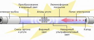
Direct the diode radiation into the lens of a digital camera. Not only a camera will do, but also a phone, laptop, video recorder, web camera, etc. IR radiation is absolutely invisible to the human eye, but electronic “eyes” register it very well. If the LED is performing its functions properly, purple flashes will be observed on the matrix.
If you don’t have a gadget that can remove it, the suspected LED can be dismantled by replacing it with a super-bright or SMD-type LED. Just make sure that the operating voltage of both elements is the same.
If the test LED emits visible light when pressing buttons on the remote control (most likely, it will be dim), then the IR LED has already served its purpose.
A more complicated method, but it does not require a camera or soldering. You can use an infrared photodiode. When infrared radiation hits the sensor of this element, a potential difference is formed at its terminals.
To test any IR LED, its radiation must be directed to the sensitive area of a photodiode previously connected to the open input of the oscilloscope.
If pulse curves appear on the device screen, the LED under test is in working condition. If you observe complete calm, then it’s time to buy a new IR LED.
Diagnostics of the LED in the flashlight
An LED flashlight, battery-powered or other types, is a fairly reliable device, but it is not immune to breakdowns. If, even after installing new batteries, the glow remains weak or completely absent, you need to check the functionality of the LEDs and their drivers.
Before diagnosing a flashlight, it would be a good idea to check the batteries (even if they have just been unpacked) on some known good device. This advice may seem trivial to some, but quite often, as practice has shown, the cause of “showdowns” with household electronics is defective batteries, which is the last thing the home craftsman realizes.
Checking the flashlight is carried out in the following sequence:
- Unscrew the cap or conical part at the front of the housing.
- We remove the LED module.
- There are two contact pads on the LED board, to which the red and black wires are connected. The red wire corresponds to the positive polarity (marked “+” on the board), and the black wire corresponds to the negative polarity (marked “-”). In accordance with the polarity, a voltage of 3–4 V (no more than 4.2 V!) should be briefly applied to the contacts. If the brightness of the LED has not changed, then it needs to be replaced. Otherwise (the LED lights up properly), the driver must be replaced.
- Replacing an LED is only possible if its board is attached to the LED module capsule with screws. If the board is mounted on hot-melt adhesive, replacement will be impractical; in this case, the entire module is replaced.
After unscrewing the board, unsolder the LED and then install a new one.
In flashlights, LEDs are installed on aluminum radiators. To ensure effective heat dissipation, a fresh coat of special heat-conducting paste, also called thermal paste, should be applied to the heatsink before installing a new LED. The old dried layer, even if quite thick, cannot be reused and must be removed.
The test of a separate LED and the simplicity of the tester’s design are clearly demonstrated in the following video from the largest supplier of electrical equipment in Russia.
Often, when one or another electronic device breaks down, we without hesitation take the victim to repair, where we are presented with a hefty bill. Meanwhile, the cause of the accident may simply be a failure of the LED, which can easily be replaced on your own.
Thus, the ability to check the performance of these elements, which are used quite widely today, will save money and reduce repair time to a minimum.
LED lamps are popular and have many advantages, but their complex design means that the location of the breakdown is not always obvious. Checking the LEDs for functionality, if they break down, allows you to determine the cause of the malfunction and decide the fate of the problematic device. Let's look at how you can find out the condition of lamps at home using a standard tester.
Device
Conventionally, all LED light bulbs can be divided into 2 categories: those made taking into account all the features of LEDs and those assembled without taking these features into account. The first category includes expensive branded designs that have a high-quality current driver and a good system for removing heat from LED chips.
this article
It is worth noting that recently some manufacturers from the first category have been producing high-power LED lamps with an ineffective cooling system. This leads to rapid degradation of LEDs and, as a result, loss of brightness of the lamp.
Continuity of individual LEDs
This type of test is one of the simplest and is done using a multimeter. A standard LED has two long contacts - an anode and a cathode. The cathode leg is slightly longer, and when viewed against the light, its electrode inside the housing is larger. In order to ring the LED, you must perform the following steps:
- move the switch to the Hfe position (this is the transistor test mode);
- find the connector on the panel marked PNP and NPN;
- The anode is inserted into slot C of the PNP zone, and the cathode is inserted into slot E of the NPN zone.
These pins are the positive and negative electrodes and cause the LED to glow. If this does not happen, then either the polarity is reversed (the diode leads must be swapped), or the element is faulty. Before checking an LED with a multimeter, it is recommended to determine where its anode and cathode are.
Since multimeters have different designs and characteristics, there are several types of sockets for testing transistors.
Read also: How to find out the expiration date of a gas cylinder
Despite the differences, they all have the required slots.
Checking the infrared diode
There is an IR diode in every remote control (television or other device). The procedure is exactly the same as in the case of testing a conventional LED with a multimeter. But checking an infrared diode is more difficult, since it is impossible to see its glow with the naked eye. When you press a button on the remote control, nothing happens externally.
Similar diodes are used to illuminate surveillance cameras in night mode. You can use your phone's camera, which sees the glow and will help resolve the issue with visual control. If you need to check the general condition and determine the source of the problem, you can simply solder a regular LED in parallel. If it starts to blink, then the IR diode is to blame, and if this does not happen, the cause of the malfunction is in the remote control itself.
Checking the diode on the board
It is often necessary to test an LED without desoldering it from the circuit. In such cases, the technique remains the same, but the technology changes. Since it is impossible to insert the LED legs into the multimeter slots, probes are used. The hole sizes of the slots for testing transistors are too small, so the probes will have to be modified. Thin contacts should be attached to the free ends, which can be used as:
- sewing needles;
- straightened paper clips;
- pieces of thin wire, etc.
Some craftsmen use a small plate of getinax or textolite foil on both sides, to which pieces of wire are soldered, forming something like a fork. It is inserted into the required slots of the multimeter, after which you can use standard (not modified) probes.
Attention! Testing LEDs in a flashlight is done in a similar way, but the design of the device most often does not allow access to the board. You have to carefully solder it from the battery pack, remove it from the case, after which you can check the elements using multimeter probes in the usual way.
How to ring an LED lamp
Let's look at how to check an LED light bulb with an E27 base, suitable for ordinary household lamps and chandeliers. Before you test an LED lamp with a multimeter, you will have to disassemble it. First you need to disconnect the diffuser. It is usually glued to the body, so you need to carefully insert a piece of thin plastic (plastic card, pick or other object) into the slot and, gradually moving it along the gluing line, separate the parts. If the seam is too strong and does not give in, you can warm it up with a hairdryer. Testing the open board with a multimeter is done using probes.
Alternatively, you can use a Krona battery. You need to select the desired polarity and check the status of the LEDs with short touches. You cannot maintain contact for a long time because the battery voltage is too high.
What you need to fix an LED light bulb
You don't have to purchase anything fancy from tools. Every family usually has a soldering iron, preferably one with a thin tip. Along with it there is usually solder and rosin (or flux containing solder) or soldering acid. You will also need tweezers - you can’t go anywhere without them.
In addition, for comfortable work, it is advisable to have a holder (third hand) or an assistant who will hold the board with LEDs. To quickly heat up the board with LEDs, we recommend using a compact gas burner. It will allow you to quickly unsolder a burnt-out LED and instantly solder the old one in its place. You can buy a gas burner at any tobacco store and the cost is about 350 rubles. But, if you do not intend to spend a lot, a turbo lighter will do.
But the main component of our repair kit is another failed LED lamp, preferably of the same type. It is she who will serve as a donor of spare parts for the light bulb being repaired. Because Usually only 1 LED burns out, then 7 others will be useful to you for repairing faulty devices.
And yes, after you fix the light bulb, you will need to glue its shade back to its original place, which means you need to stock up on super glue (or similar transparent glue for plastic).
Checking the LED spotlight
First you need to determine what type of LED is installed in the spotlight. There may be two options:
- board with small SMDs;
- one large yellow element.
The LED is checked for serviceability based on its type. For a board with SMD, the already discussed method of testing with a multimeter is used. This method is not suitable for large yellow samples, since their supply voltage ranges from 10 to 30 V, which is too high for a multimeter. There is only one way to check such a device yourself - using a known working, serviceable driver that matches the operating parameters of the LED being tested.
How to check LED strip for performance
It is difficult to check the entire LED strip using a multimeter at once. It will not be possible to make it glow; only sometimes a faint glow occurs when checking in Hfe mode. You can check all the LEDs one by one.
Most often, contact tracks fail, which are checked along the entire length of the tape. It is conventionally divided into equal sections consisting of 3 LEDs. The border of each is marked on the tape with a transverse line with contacts. Touching them, check each segment, identifying the damaged area. In addition, it is necessary to check the power supply of the tape with a multimeter, since it is also subject to stress and periodically fails.
How to choose
To select an LED driver, it is necessary to comprehensively consider the characteristics of the device:
- input and output voltage;
- output current;
- power;
- level of protection from harmful influences.
First, determine the power source. A standard AC voltage network, battery, power supply and much more are used. The main thing is that the input voltage is within the range specified in the device passport. The current must also be suitable for the input network and the connected load.
Figure 5. Types of blocks
Manufacturers produce devices with or without housings. The housings effectively protect against moisture, dust and negative environmental influences. However, to integrate the device directly into the lamp, the housing is not a necessary component.
Other verification methods
In addition to a multimeter, you can check LEDs using a battery. The best option is a CR2032 battery, which is used in the computer motherboard. Its voltage is 3 V, which is enough for most LEDs.
It is possible to use 4.5 or 9V batteries, but in such cases you will need to connect a ballast resistor, which gives a voltage drop to safe levels. For Krona you will need 750 Ohms, for 4.5V batteries - 150-200 Ohms.
The LED strip can be checked with a 12 V battery. These are found in remote controls and doorbells. By connecting the contacts of the tape to the corresponding poles of the battery, areas with burnt-out elements are determined. No less problematic elements are the connection areas of individual parts of the LED strip - connectors that oxidize and stop conducting current. Before you start dialing, you need to check their condition - perhaps the problem lies there.
Important! If you need to test a UV LED, you should be careful when connecting it to a power source. Such devices are sensitive to overvoltage and easily fail. The nominal value for which the ultraviolet LED is designed is 3.4-4 V, these figures cannot be exceeded.
Device and circuit of the LED chandelier driver.
LEDs just need current, that is, a source with a high output resistance. If the LED is connected to a voltage source (whose output resistance is much lower than the resistance of the diode), then the current after a certain voltage will increase very quickly until the diode burns out.
Power supply (inverter) for sequential switching of chandelier LEDs
And this driver is the simplest device, I soldered these in the 7th grade, in a radio club. It is a stretch to call it a current source, due to the fact that its output resistance is greater than or equal to the load resistance. We calculated this above.
We open it up and see a simple board without a single active element:
Let's disassemble the LED driver
Brown barrels are ballast (limiting) capacitors. They are for an operating voltage of 400 V, a capacitance of 0.33 μF:
LED Driver Limiting Capacitor
and 0.82 µF:
LED Driver Limiting Capacitor
On the cases they say 334 and 824, respectively. What does this mean - look for “Alphabetical designations on capacitors”. I wrote about this in an article on repairing a chandelier controller with a remote control, link above.
View from the soldering side:
Driver for powering serial chandelier LEDs. Solder side diagram.
And finally,
Main conclusions
It is not difficult to check LEDs with a multimeter if you understand the principle of their operation. The main task is to prepare the conditions, modify the probes or make special contacts. The correct polarity plays an important role, changing which will not allow even a working element to glow. The process does not take much time; preparation, dismantling or disassembling of devices takes longer. The general principle is to apply the appropriate voltage to the problem element, from which it should light up if it is in working condition. If the glow is not observed even when the polarity is changed, it means that the LED (or section of the strip) is faulty and must be replaced.
Read also: Rating of budget wood routers
Testing an LED with a multimeter is the easiest and most correct way to determine its performance. A digital multimeter (tester) is a multifunctional measuring instrument, the capabilities of which are reflected in the switch positions on the front panel. LEDs are checked for functionality using functions present in any tester. Let's look at the testing methods using the DT9208A digital multimeter as an example. But first, let’s touch a little on the topic of the reasons for the malfunction of new light-emitting diodes and the failure of old ones.
Solving driver problems
Driver problems are a fairly common problem with LED lamps. Most often, a resistor or capacitor burns in the driver.
Using the measuring instruments available to the home craftsman, it is quite problematic to determine the level of performance of this element. Therefore, it is recommended to simply replace it with a working one with similar parameters.
The reasons why a capacitor fails may be an initial manufacturing defect or regular overheating of the module as a result of poor-quality heat dissipation.
It is not always possible to find a suitable part in lighting stores. It is better to immediately go to the radio market or to a place where radio electronics are sold and try to find the thing you need there.
When it is purchased, you will need to dismantle the faulty unit and put a working element in its place.
To correctly disassemble and repair LED light bulbs, you do not need complex, expensive equipment. A minimal set of simple tools will help you troubleshoot problems.
A multimeter will allow you to check the presence of voltage in the circuit, make it possible to detect the presence of breaks and show how efficient the remaining parts of the circuit are.
A multimeter is a universal device designed to measure the main basic parameters of various electronic products. With its help you can find out what condition the LEDs of any LED product are in.
The heating temperature at the time of soldering should not exceed 260°. A simple soldering iron heats up more, so you need to wind a piece of copper wire with a cross-section of no more than 4 mm onto its tip in a tight spiral. The more you can lengthen the tip, the lower its operating temperature will be.
A soldering device with rosin and solder will be required to repair breaks found in the circuit and subsequently replace damaged parts and elements.
With a small screwdriver you can carefully separate the control elements from the lamp body, and with a thin, durable stationery knife you can delicately detach the parts from the circuit board.
Users also often encounter problems such as blinking light bulbs and burning lamps when the switch is off. What causes these malfunctions and how to eliminate them we discussed in our other articles:
- Why LED lights blink: troubleshooting + how to fix
- Why LED lamps burn when the switch is off: reasons and solutions
The main causes of malfunction and failure of LEDs
A feature of any emitting diode is its low reverse voltage limit, which is only a few volts higher than the drop across it in the open state. Any electrostatic discharge or incorrect connection during circuit adjustment can cause the LED (abbreviation for Light-emitting diode) to fail. Ultra-bright, low-current LEDs, used as power indicators for various devices, often burn out as a result of power surges. Their planar counterparts (SMD LEDs) are widely used in 12V and 220V lamps, strips and flashlights. You can also verify their serviceability using a tester.
It is worth noting that a small proportion of defective LEDs (about 2%) are supplied from the manufacturer. Therefore, additional checking of the LED with a tester before mounting it on a printed circuit board will not hurt.
How to connect to LEDs
You can connect the driver to LEDs even without special skills. Contacts and connectors are marked on the housing.
INPUT marks the input current contacts, OUTPUT indicates the output. It is important to maintain polarity. If the connected voltage is constant, then the “+” contact must be connected to the positive pole of the battery.
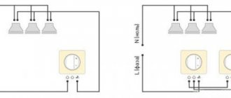
When using alternating voltage, take into account the marking of the input wires. Phase is applied to “L”, zero is applied to “N”. The phase can be found with an indicator screwdriver.
If the markings “~”, “AC” are present or there are no symbols, polarity is not required.
Figure 6. Connecting diodes in series.
When connecting LEDs to the output, it is important to observe polarity in any case. In this case, the “plus” from the driver is connected to the anode of the first LED in the circuit, and the “minus” to the cathode of the last one.
Figure 7. Parallel connection.
The presence of a large number of LEDs in a circuit may necessitate dividing them into several groups connected in parallel. The power will be the sum of the powers of all groups, while the operating voltage will be equal to that of one group in the circuit. The currents in this case also add up.