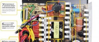
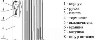
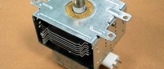
Any heater - oil, infrared or convection, regardless of its type, type and manufacturer, even the highest quality and reliable, can break down at any time and require repair. This is what happened with the Bimatek PH300 micathermic heater, which a friend brought to me. The heater did not heat up, the temperature indicator did not light up, although the heater only worked for six months and was still under warranty.
Anyone who has dealt with the repair of household appliances under warranty knows that this is a troublesome task. You need to find a warranty workshop, take the heater there, wait a month and then spend time picking up the repaired one. It is not a fact that the repair will be free. If the workshop decides that the heater has failed due to your fault, you will also have to pay for the repair service. Therefore, if a product, for example a heater, is simple, then it makes sense to try to repair it yourself. As it turned out, the protective thermal fuse had failed, but to get to it, we had to almost completely disassemble the heater.
Attention! Before starting work on inspecting and repairing the heater, it is necessary to disconnect it from the power supply by unplugging the heater's power plug from the socket.
Why the heater does not heat up - troubleshooting
If suddenly the heater stops working and the power connection indicator does not light up, then first of all you need to check the presence of supply voltage in the electrical outlet. The circuit breaker at the entrance of the electrical wiring to the apartment could have tripped, the contact at the point where the wires are connected to the socket could have broken, or the electrical socket itself could have failed.
You can check the serviceability of the outlet in two ways by connecting any electrical appliance to it, such as a table lamp or hair dryer, which is preferable. Or connect the heater to a different outlet. If the heater starts to heat up, it means the socket is faulty.
If the problem is with the heater, then it is quite possible that it has overheated and its overheat protection system has tripped, or the plug was inserted into the socket, but they forgot to turn on the switch on the heater body or set the temperature control knob to the desired position (if any). Therefore, before drawing conclusions, you need to check what position the switches are in and wait until the heater cools down.
If all checks are unsuccessful, it means that the heater is out of order and requires repair.
Reasons for heater failure
An oil heater stops working for various reasons, but all damage can be electrical or mechanical.
In the first case, electrical equipment fails, this can be a heating element and elements of the control unit, including thermal fuses, a thermal relay and a switch. In rare cases, malfunction occurs due to faulty electrical wiring.
Mechanical damage involves deformation of the housing, including the formation of cavities through which oil leakage may occur. This problem is the result of metal corrosion. It is very easy to determine such a malfunction; in this case, an oil stain forms under the heating device.
Electric heater repair instructions
Repair of any electrical appliance begins with an external inspection. The first thing to check is the power plug. It should not have visible mechanical damage, darkened plastic or cracks in the body. The pins of the plug must be firmly fixed in the housing and not have any blackening. The power supply cord must not have any mechanical damage. You need to especially carefully inspect the place where the cord exits the plug body. This is where the cords often fray.
It is also necessary to look through the mesh or perforation inside the heater body and make sure that there are no broken or burnt wires in the visible space, the wires are not burnt at the points of connection to the connectors and fixed with nuts, and the heating elements (heating element or nichrome spiral) do not have mechanical damage.
If an external inspection does not reveal obvious defects, then to further search for the causes of the heater failure, you will need a measuring device. A dial tester or a multimeter turned on in low resistance measurement mode is best suited for these purposes.
Without disassembling the heater, you can use a tester to check the serviceability of the power cord at the point where it exits the plug housing. To do this, you need to set the heater switches (if any) to the operating position, connect the ohmmeter probes to the pins of the plug (conveniently using an alligator clip), and press the cord to the plug body along the line of its exit from the plug, swing from side to side. If the tester needle or multimeter readings change even for a moment, it means the repair is almost complete. All that remains is to replace the plug. The resistance value of the heating element is, depending on the power of the heater, 10–150 Ohms and, if desired, you can accurately calculate it using the online calculator below.
| Online calculator for calculating the resistance value based on power consumption | |
| Supply voltage, V: | |
| Power, W: | |
Electrical circuits of heaters
The photo below shows five standard, widely used electrical circuits for heaters.
Scheme No. 1 is the simplest, it is a power plug with a cord that is connected to the heating element directly or through a terminal block using a threaded connection or slip-on terminals. According to this scheme, a heater of the Tram stove type is assembled. To turn on a heater made according to this scheme, just insert the plug into the socket.
Scheme No. 2 differs from the previous scheme in that, for convenience, it is installed on the body of the electric heater switch. As a result, during operation it is no longer necessary to insert and remove the plug from the socket each time to turn the heater on or off.
Heaters assembled according to scheme No. 3 are supplemented with a thermal fuse, which will open the power supply circuit of the heater if it overheats when dropped on the side or if, in violation of the operating rules, things are placed on the heater to dry. In some models, in addition, in series with the thermal fuse, a position sensor is installed that turns off the heater if its position deviates from the working one. As a rule, the operating position of the heater is vertical.
Scheme No. 4 has two heating elements and an additional switch. Heating elements can be of the same power or different. This circuit solution allows you to regulate the power of the heater by simply turning the switches on or off, thereby regulating the heat it generates. For example, if the heater has two heaters with a power of 1000 and 2000 watts. Then, when On1 is turned on, the power will be 1 kW, when On2 is turned off, but On1 is on, the power will be 2 kW, and when On1 and On2 are turned on, it will be 3 kW.
For convenience, some types of heaters are equipped with a biscuit switch. When turning the switch knob clockwise, with each click the power increases by 1 kW.
According to scheme No. 5, electric heaters of the fan heater type are manufactured. An electric motor with an impeller is additionally installed in them. To prevent overheating of the heating elements, it is impossible to turn them on without turning on the fan. This is ensured by the additionally installed switch On1. Fan heaters must be equipped with a self-resetting thermal fuse to turn off the heating elements in the event of a fan failure. If you do not turn on the heating elements, the fan heater can be used as a regular fan for cooling in hot weather.
In expensive models of electric heaters you can find a temperature controller. When the regulator sets the set air temperature, when it is reached, the heater will turn off and turn on only after the air temperature drops below the set value.
Indicators of operating modes on neon bulbs or LEDs can be installed in the electric heater circuit. Some models have backlit switches that already have neon bulbs installed. The indicators do not directly participate in the operation of the heater, but only signal its operating mode.
How to disassemble an electric heater
If the heater stops heating and an external inspection does not allow us to determine the cause of the malfunction, then it will have to be disassembled for repair.
Let's look at the repair sequence using the example of a modern micathermic heater Bimatek PH300 (photo at the beginning of the article), assembled according to the most complex of the electrical circuits presented above. Knowing how to repair such a heater, simpler ones can be repaired without difficulty.
You need to start disassembling from the input side of the power cord. Typically the cord enters the lid from the side. To remove the side cover from the Bimatek PH300 heater, you need to unscrew all the visible screws holding the cover and two more countersunk screws. One of them is closed with a decorative plug, which is located below the control knobs.
To remove the plug, use the blade of a screwdriver or knife to pry the plug from the side of the latch and pull the latch inward. The plug will come out easily.
A hole will open in which there is a screw for the side fastening of the cover to the base. The second secret wine was hidden under a sticky sticker, next to which there was another yellow sticker with the warning message “If the seal is damaged, the warranty is void!”
So if the heater is still under warranty service and you are not confident in your abilities, if possible, it is better to contact a service center for repairs under warranty.
The side cover has been removed and access to all contacts of controls and heating elements is now open. All that remains is to use the tester to find and replace the failed part.
Troubleshooting a micathermic heater
The first thing you need to do is carefully inspect all the wires, where they are connected to the terminals and connectors. If the external inspection does not produce results, then you need to proceed to checking the circuits using a tester or multimeter. The order in which the components are checked does not matter, but I always start checking the components with the lead wire.
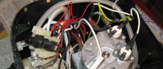
The three-core power cord goes into the side cover, where it is secured by a pressure plate with two self-tapping screws. The two ends of the blue and red insulated wires end in a two-pin connector, and the yellow-green ground conductor ends in a tab screwed to the metal base of the heater. The yellow-green wire does not interest us when troubleshooting, since it does not directly participate in the operation of the heater, but serves only to protect a person from electric shock.
Checking the power cord
To check the power cord, you must first prepare the device by setting its switches to resistance measurement mode. Next, touch any pin of the plug with one end of the probe, and touch the ends of the green and red wires in turn with the other. When you touch one of the wires, the device should show zero resistance. Next, touch the second pin of the plug and check the second wire. In this case, it is advisable to hold the probes and pull the cord and bend it; the resistance should not change and sooner be zero.
If the resistance is significantly greater than zero as a result of a faulty plug or a frayed cord at its base, then the plug should be replaced. The article “Electrical plug” is devoted to checking and replacing the electrical plug.
Checking the operating mode switch
If the power cord is in order, then proceed to check the heater operating mode switch.
The switch terminal to which the brown wire goes is common and is supplied with supply voltage. To check the switch, you need to set it to position III, in which the common terminal must be connected to the other two terminals. Now it is enough to measure the resistance between the common terminal and the other two, it should be equal to zero. If the switch is set to position II, the middle contact will remain connected to only one of the other two. In position I, only with contact not yet tested. In the zero position, no contact should be connected to another. If the switch is in order, then you need to look for the cause of the heater failure in another place.
Checking the operation of the bimetallic thermostat
A bimetallic thermostat is installed next to the mode switch. Its operating principle is based on the properties of different metals, which increase or decrease in size with temperature changes in different ways. If you connect two plates of different metals into one, then when the temperature changes, the plate will begin to bend. And if an electrical contact is established on such a plate, then by bending the plate it will be possible to control the temperature of turning on or off electrical appliances depending on the ambient temperature. Each of us encounters the beneficial properties of bimetallic strips every day. For example, an electric kettle is turned off by a bimetallic plate heated by steam from boiling water.
To check the serviceability of the thermostat, just touch the probes of the multimeter to its terminals and turn the handle from lock to lock in any direction. In almost the entire rotation range, the resistance of the thermostat should be zero. If this is not the case, then it is usually enough to clean the contacts, which are clearly visible from the side, with fine sandpaper.
If you need to remove the thermostat, for example, for replacement or repair, you must first remove the adjustment knob. It stays on the axis due to a tight fit. To remove the handle, you need to carefully pry it off on both sides with the flat blades of screwdrivers. The handle will be removed from the axle with a little effort.
There are two screws under the handle. It is enough to unscrew them and the thermostat mechanism will be released.
Checking the serviceability of heating elements
Now it's time to check the heating elements connected to the switch and thermostat using a six-pin connector.
As it turned out, the micathermic heating element is composite and consists of two. One has a resistance of 60 ohms, the second 100 ohms. To check the heating element, it is enough to measure the resistance between the red, blue and brown wires. The check showed the serviceability of the micathermic heater.
The article on the site “How to check an electric heater” is devoted to checking the heating elements of electrical household appliances.
Checking the vertical position sensor
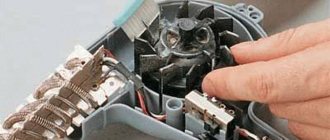
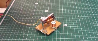
The position sensor is a weight mounted on a lever with a counterbalance spring attached to the opposite end of the lever. When the heater is in a vertical position, the weight stretches the spring and presses on the built-in microswitch. The supply voltage is supplied to the heating elements. If the heater is tilted on its side, the force of gravity will reduce the effect on the spring, it will move the lever away from the microswitch, the circuit will break, and the current will stop flowing to the heating elements.
There are two wires coming from the position sensor, white and brown. To check, it is enough to measure the resistance between them with a multimeter. When the heater is in a vertical position, the resistance of the position sensor should be zero. When tilted - infinity. The position sensor turned out to be OK.
Checking the health of the thermal fuse
It remains to check the thermal fuses connected in series, of which there were three and all of them were installed behind the micrometric heater plate. A pair of white wires went from the thermal fuses to a six-pin connector, the same as the wires from the micathermal heater. A test with a multimeter showed an open circuit in the thermal fuse circuit. It became clear that one of the thermal fuses was faulty.
Further disassembly of the heater was required. To do this, I had to remove the second side cover and the protective mesh, which is removed after removing the screws by moving it to the side. Access to check two self-resetting thermal fuses has opened.
To check the thermal fuses, with one end of the multimeter probe you need to touch the white wire that fits the six-pin connector, and with the second probe, piercing the insulation with a needle pressed to it, touch the wire connecting the thermal fuses. The check showed the serviceability of the fuses available for testing. All elements have been checked, except for the thermal fuse behind the micathermic heating element. That means it's faulty.
I had to remove the heating element, for which it was enough to unscrew the four screws in the corners and move it to the side. The following view opened.
The thermal fuse was located in a fiberglass tube and was attached to the heater body with a screw using a metal clamp.
As it turned out, the tube contained a self-recovering thermal fuse SF192E, designed for an operating temperature of 133˚C and a load current of up to 10 A at a voltage of up to 250 V. An additional check with a multimeter confirmed that the thermal fuse was faulty.
The thermal fuse was connected to the wires by crimping with a brass strip. Using an awl, the end of the strip on the thermal fuse side was bent, the thermal fuse was removed and a similar one, type G4A00, designed for an operating temperature of 128˚C and a load current of up to 10 A at a voltage of up to 250 V, was pressed into its place. The operating temperature of the installed thermal fuse was 5 degrees lower than a failed one. But taking into account the maximum heating of the heater body is only 65˚C, such a replacement will not affect the protective functions and performance of the heater.
Before assembling the heater, all connectors were connected to each other, the multimeter probes were connected to the pins of the power plug, and all operating modes of the heater were checked. The resistance in mode switch position 0 was infinite, in position I it was 156 Ohms, in position II – 100 Ohms and in position III – 56 Ohms, which indicated that the heater was in full service.
After assembly, the heater was connected to the network and confirmed its functionality. The repair of the heater is completed and only tool marks left on the plastic plugs remind of its malfunction.
Features of repairing a heater with ceramic heating elements
They brought me a seemingly ordinary fan heater, such as Timberk TFH T15DDL, for repair due to a decrease in heating efficiency.
When connecting the heater to the network, it was discovered that the fan was weakly blowing air that was slightly warm. The heating mode switch and temperature controller functioned normally. To find the problem, I had to open the heater. The first step was to remove the dust that had accumulated in the radiator of the heating elements. The fan began to blow harder, but the heating of the air remained weak.
Measuring the voltage at the terminals of the heating elements showed a value of 220 V, which indicated the serviceability of the electrical circuit. The measured current consumption of the fan heater in maximum heating mode was 1.1 A instead of the required 8 A, which indicated a malfunction of the heating elements.
This was my first time encountering such a heating element. It turned out that in this fan heater the heating element consists of 14 metal-ceramic plates sandwiched between eight aluminum radiators. This entire package is inserted into a rectangular frame made of heat-resistant plastic and is held in place by four latches. Aluminum radiators perform several tasks at once - they hold ceramic heaters, remove heat from them and supply power voltage to the metal-ceramic plates.
Attention, due to the fact that the supply voltage is supplied through an aluminum radiator, touching it while the heater plug is inserted into the power outlet is dangerous to life!
For better heat dissipation and electrical contact, the sides of the metal-ceramic plates pressed to the radiator are coated with electrically thermally conductive paste.
Heating metal-ceramic plates are radioelements called posistors. The operating principle of a posistor is that its resistance depends on the temperature at which it is heated. The more the posistor heats up, the higher its resistance, and according to Ohm’s Law, less current will flow, and as a result, the heater will generate less heat.
Thanks to this property, according to the developers of metal-ceramic heating elements, when the temperature reaches 300°C, balance occurs, the resistance of the posistor increases to such a value that the temperature no longer increases. This ensures the safe continuation of operation of the fan heater, even when the fan blowing air is broken and does not rotate or is clogged with dust.
Measuring the resistance of the heater sections with a multimeter showed a resistance of about 1000 Ohms, instead of the proper 112 Ohms. Surprisingly, it turned out that the resistance is not the same for all ceramic-metal plates. This could only happen if the cermet plates overheated, which, based on the principle of their operation, should not happen. The conclusion is that the ceramic heaters were installed of poor quality and to restore full functionality of the fan heater they will need to be replaced.
To repair a fan heater, you can buy a ready-made heating block, a ceramic heater type MZFR-J-1800W-220V, designed for repairing fan heaters. Its appearance, overall dimensions and connection diagram are shown in the photograph above. MZFR-J-1800W-220V costs about $10.
Do-it-yourself repair of the Value 600E uninterruptible power supply (circuit for 400E, 600E, 800E).
After sending, the data is displayed on indicators based on the principle of dynamic control.
Too dry air increases the risk of infections, causes wood to shrink and wallpaper to crack along the edges.
If you suspect a broken cord, check it and replace if necessary.
Well, damn it, if there’s something better, I’ll definitely install it, but for now it’s fine. And for indoor flowers, dry air is completely destructive. If it is, you will have to deal with the electrical part. Repeat this process until the bleach smell goes away.
Caring for an air humidifier The season for using an air humidifier is autumn-winter, but in some areas this unit has to be used almost every day. The main thing is to fit the relative humidity indicators within the required limits; doctors recommend a value of 45 - 60 percent. It turns out that all pediatricians will confirm that moist, cool air is the safest for the spread of winter colds - the mucous membranes do not dry out and a barrier from bacteria is maintained. If the resistor was a wire resistor, then it is even easier to clean it mechanically, slowly and carefully, and
Nav view search
Scale has a detrimental effect on equipment, reduces its performance and reduces the service life of the product. It's more likely silver. It turns out that all pediatricians will confirm that moist, cool air is the safest for the spread of winter colds - the mucous membranes do not dry out and a barrier from bacteria is maintained. Two stripes are visible on the resistor: 1 - gold, this is definitely gold 2 - gray or silver. Hydrogen peroxide is not diluted.
And you can use the humidifier as intended. The latter is supplied into the room space with the help of a fan. A piezo crystal quartz plate is exposed to a current frequency exceeding the threshold of audibility, and oscillations are created in time with the voltage. What can you control in a humidifier, you ask?
The outlet pipe is made from a piece of plastic sewer pipe with a diameter of 50mm. Power supply To power the device, a power supply with an output voltage of 12V and a maximum current of 3A is used. As you probably guessed, I used hot glue here too. When it does not rotate, replace the motor. It turned out that when water gets on the piezo emitter, the generation is disrupted. Repair of HONGFEI model “HB-7530L12” fan for air humidifiers.