A surge protector is a useful device that protects sensitive electrical appliances from power surges and impulse noise.
Externally, a household filter resembles a regular extension cord, but it is additionally equipped with a built-in unit that absorbs all frequency fluctuations.
To protect against large surges, the device is equipped with a fuse, which in case of critical overloads instantly disconnects electrical appliances from the network.
Like any other devices, surge protectors can break down during intensive use.
One of the most common reasons for the failure of a surge protector is a breakdown of the on-off button, or rather, burning of the contacts inside this button.
First, when turned on, it begins to spark, heat up and make strange sounds, and over time it stops working altogether. If the filter is used frequently, the button may wear out physically or become mechanically damaged.
Attention! If the surge protector button begins to spark, heat up and/or crackle, further operation of the device is unsafe! You should immediately disconnect the filter from the mains to avoid fire! For safe operation of the filter, you need to check the condition of the switch contacts and, if necessary, clean them of carbon deposits.
Let's look at the button diagram of a typical surge protector:
As can be seen from this diagram, there is nothing complicated in the design of the surge protector power button , so you can repair it or replace it with a new one yourself.
Repair - what to do if the surge protector button is broken
If, when you turn on the surge protector button, extraneous sounds begin to be heard, which are accompanied by the smell of melting plastic, the device should be immediately de-energized. Next, you need to disassemble the surge protector and check the condition of the contacts on the switch.
To do this you will need the following tools:
- soldering iron,
- crosshead screwdriver,
- tester,
- sandpaper-zero.
If the contacts are burnt out, the tester readings will confirm this (in this case, there will be no voltage at the output from the button in the “On” position). To clean the contacts, the switch needs:
- Disassemble the surge protector housing by unscrewing the mounting screws;
- Unsolder the button and remove it from the filter housing. The button is held in the housing by plastic clips, which should be carefully squeezed out.
- Disassemble. To do this, you need to disconnect the key by picking it up with a flat-head screwdriver.
- Take out the contacts and clean off any black deposits.
- Assemble the button. After this, we assemble the button in the reverse order, install it in place and solder it.
If the contacts have burned very badly and melted the plastic of the switch housing, it should be completely replaced.
To do this you need:
- Disassemble the filter;
- Unsolder the button;
- Remove the switch from the housing;
- Install a new one in its place (sold in radio parts stores, costs about 30 rubles);
- Solder the button and assemble the filter housing.
Often the button on the surge protector does not work due to mechanical damage. The most common case is the breakdown of the latches that hold the switch key in the housing. In this case, it is not necessary to buy a new button - the latches can be restored.
To do this you will need the following materials and tools:
- screwdriver (or drill) and drill with a diameter of 3.5 mm;
- toothpick;
- cotton swab;
- side cutters.
The process itself is very simple:
- A through hole is drilled in the key into which a cotton swab is inserted (it will act as a latch).
- A toothpick is inserted inside the cotton swab for greater rigidity. On both sides, the improvised retainer is trimmed with side cutters so that on each side it protrudes approximately 3-4 mm.
- Now all that remains is to insert the key into the body - to do this, just slightly bend the sides of the seat with a screwdriver.
VIDEO INSTRUCTIONS » alt=»»>
How to make a surge protector directly, without a button
If the old button has completely failed and you don’t have a new one at hand, you can connect the surge protector directly, turning it into a regular extension cord.
To do this you need to do the following:
- Open the mains voltage filter housing by unscrewing the mounting screws with a screwdriver;
- Unsolder the wires from the button and solder them according to color, bypassing the button;
- Insulate the joint with insulating tape or heat shrink;
- Assemble the extension cord and test its functionality.
To avoid the surge protector switch problems described in this article, consider the maximum power rating of the connected load and the maximum load current when selecting a device.
VIDEO REVIEW » alt=»»> If the total power of the equipment exceeds the maximum permissible filter power, then you should opt for a more powerful model.
The uninterruptible power supply turns off by itself
Everyone knows that power surges are dangerous for household and computer equipment, as well as electronic components of power tools and industrial equipment. Unfortunately, power surges are not uncommon in the power grids of our cities, and even more so in villages.
To protect equipment from these phenomena, the UPS device was invented, which is an abbreviation of its name: uninterruptible power supply. UPS is his English. abbreviation.
Thanks to modern technologies, the UPS effectively smoothes out voltage surges and radio frequency interference, and in the event of a complete power outage, it switches to powering consumers from the backup battery.
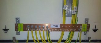
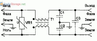
Scheme of SF protection against network interference
A typical network filter circuit is the basis of all devices of this type, with the exception of additional details. The classic is connecting to the points: Ground, Phase and Zero. A varistor VDR 1 is installed at the input. It suppresses voltage surges in the mains current. With a high voltage surge, the resistance of the varistor drops sharply, thereby preventing the interference from passing further through the circuit.
To dampen small voltage changes, inductor Tr1 and three capacitors C are used. Capacitors C1, C2 and C3 are reactive radio components that constantly change the resistance level. It increases sharply when the current frequency changes.
Normal current passes through the filter unimpeded. At the same time, high-frequency interference is delayed in the SF. The filter resistance is directly proportional to the current frequency. Both indicators increase simultaneously, which makes it possible to delay interference on the way to the consumer.
Note! A three-wire power supply network may be subject to interference in the phase-zero, ground-phase, and ground-zero sections. Effective suppression of such negative phenomena is carried out by normal standard grounding of the SF.
How to make a surge protector directly, without a button
If the old button has completely failed and you don’t have a new one at hand, you can connect the surge protector directly, turning it into a regular extension cord.
To do this you need to do the following:
- Open the mains voltage filter housing by unscrewing the mounting screws with a screwdriver;
- Unsolder the wires from the button and solder them according to color, bypassing the button;
- Insulate the joint with insulating tape or heat shrink;
- Assemble the extension cord and test its functionality.
To avoid the surge protector switch problems described in this article, consider the maximum power rating of the connected load and the maximum load current when selecting a device.
VIDEO REVIEW
POWER FILTER FOR A COMPUTER FROM A REGULAR EXTENSION CORDE
Nowadays, the 220 volt electrical network is heavily polluted with a lot of interference and short-term voltage surges that penetrate from the network and prevent the equipment from working properly.
Workwear in Simferopol High-quality workwear in Simferopol only on Elab and at a promotional price.
To combat interference in a 220 Volt household network, surge protectors are used, which are often very expensive. Cheap filters in practice do not meet consumer expectations. Therefore, at home, you can purchase a simple extension filter with a switch and remake it yourself.
Inside such an extension cord there is only a varistor connected in parallel to the supply conductors and limiting short-term high-voltage pulses that are sometimes present in the network. If such protection is triggered, there is a fuse button on the case that must be pressed to restore the functionality of the extension cord again.
The UPS does not support the load - this and other failures of uninterruptible power supplies
In case of any malfunction, you should first read the instructions for the device. Depending on the manufacturer and model, the same malfunction may manifest itself in different ways. Diagnosis of each UPS and repair may vary, depending on the definition of typical problems.
Symptoms of uninterruptible power supply malfunctions can be different, but the main ones are:
- does not support the load when the power is disconnected from the network;
- does not turn on;
- The UPS beeps constantly;
- overheats;
- The UPS clicks or shuts down on its own.
In some cases, you will be able to repair the device yourself, but you should remember that the UPS device is electrical and will require basic skills in assembly and disassembly.
Be careful when disassembling the device
The most common problems with uninterruptible power supply systems are dust and battery wear. Both of them arise as a result of long-term use. Equipment needs regular cleaning from dust; you should not leave the device in the room where repairs are being carried out - construction dust is the most dangerous for it.
UPS malfunctions, description
A UPS failure puts all equipment at risk, so you should know how to check the UPS and its battery for functionality. Methods for eliminating minor faults are necessarily described in the user manual for the device, so it is recommended that you study it first. If this does not work, you should try to identify the problem yourself.
Beeps continuously
The UPS starts beeping if the power is turned off and the equipment switches to battery power. In this case everything is fine. It is for these purposes that this device was created. The user just needs to shut down the entire system and turn off the power to the device.
If such a squeak occurs regularly, while there is voltage in the network, you may need to test the electrical network and understand the causes of power surges. In this case, the uninterruptible power supply is not to blame, the problem is elsewhere.
Pay attention to the device indicators
Another reason for the UPS beeping is overload. In this case, the device does not pull the equipment connected to it. You can determine the source of problems by connecting and disconnecting devices one by one. The solution to the problem will be to purchase a more powerful uninterruptible power supply or turn off part of the equipment.
Doesn't turn on after power is applied
If electricity appears in the network, but the UPS does not turn on, you should check the health of the battery, the connection to the network and the voltage level. The UPS will not be able to operate for a long time if the network voltage is low for a long time. In this case, the battery will be discharged and the device will no longer turn on.
Sometimes, it is enough to connect the UPS to the network and just wait a while, the battery will charge and the device will start working. You should know how to check the UPS to see if its power button is working; it may be pressed. Wire breaks are a common problem with uninterruptible power supplies. When there is a heavy overload, some brands of UPS refuse to work; it is enough to turn off everything and check that it turns on independently.
It turns itself off and gets very hot
If there is voltage in the network, the uninterruptible power supply may turn off due to an overload at the output
It is important to consider at what point the device turns off. If during a power outage, then most likely the problem is in the battery, you should check its performance
In the case when the device disconnects the load while operating from the network, it is quite possible that the software settings are to blame. You should check the standard settings and adjust them if necessary.
After opening the case, you can notice obvious problems
The reason for unstable operation of the device may be the use of non-branded accessories. In addition, it is likely that other problems will appear in the operation of the UPS. The uninterruptible power supply may turn off due to overheating. In this case, you should check the serviceability of the cooling system and make sure that there is no debris obstructing the free circulation of air, otherwise the device will turn off.
The UPS should be selected carefully, according to the voltage of the connected devices. If there is an overload, the uninterruptible power supply will turn off, just as if there is insufficient load. Devices from some manufacturers detect a load below the set power as the absence of working devices and turn off to preserve their own charge.
Details
Surge filter circuit for 220 V
- High-frequency oscillations, hitting the inductor, increase its degree of resistance and therefore will not pass further (inductive resistance is proportional to the frequency).
- Contacts on the capacitor will dampen high frequencies if the capacitance is chosen correctly (the resistance of the capacitor with this connection method is inversely proportional to the frequency of current oscillations).
In two circuits, a resistor with a huge resistance will be connected in parallel with the capacitor.
It will act as a load for an element such as a capacitor when the power is turned off (a free type of charge may begin to accumulate on the capacitor, which is dangerous even after 100% disconnection of the filter from the AC mains). You can make the simplest surge protector yourself. By the way, it is best to buy a ferrite filter in the form of an extension cable with a detachable diameter. Its purpose in the operation of the circuit is to suppress high-frequency interference along the power supply circuit by increasing the conductor inductance, as well as absorbing radiation directly by the ferrite. This is an excellent solution for connecting home appliances to the power supply. Other implementations of the network electrostatic precipitator are also possible. As an example, we can cite the diagrams that are used in the Pilot technique. We provide you with instructions on the assembly process of a conventional network filter yourself. Assembling a filter from the proposed circuits is quite simple, and this does not require printed circuit boards or a single housing on an extension cord. With a good choice of the size of the elements and their layout, they can be placed in the housing of an inexpensive varistor filter for the network. The circuit that is available must be cut (contacts from the varistor to the sockets, leaving the varistor itself), and the elements will be placed in accordance with the diagram and soldered. Everything should work out as planned.
Capacitors C1 and C2 can be combined into one if there are the necessary indicators and free space. Or, on the contrary, dial using several parallel connections, if free space allows. It is best to use film capacitors from 0.22 to 1 µF. It is better to take the maximum permissible voltage with a reserve (in case of interference with sudden voltage changes), for example, up to 680 V. Resistance R3 should be from 0.5 to 1.5 MOhm. It is also better to take power with a reserve for better thermal output of 0.5 W. In circuit No. 3, the coils and capacitor will be changed, and it is the coils that have the most optimal inductance indicators for their small size and the tasks facing them. It turns out that you will use much fewer parts for soldering.
How to take it apart correctly?
Disassembling a regular Pilot filter begins with unscrewing the screws, as, indeed, in most other cases, but in some non-separable models the housing may be without bolts using rivet screws. Usually the fastener is installed on the back, it is often covered with factory stickers, but it can also be found on the front, right in the slots of the sockets. For additional fixation, there are plastic latches at the junction of the two halves of the case. When opening, do not make sudden movements or use force so as not to damage the structure. If the device has never been disassembled, there will be a warranty seal on the case.
You can try to push out just the button using a flat-head screwdriver, because in such devices, most often the contacts in the switch become clogged with dust, or the cord itself breaks.
Next, use the tool to diagnose and repair components. You will need:
- soldering iron;
- screwdriver (phillips and flat);
- tester;
- needle file or sandpaper;
- tweezers;
- hair dryer for blowing after cleaning contacts.
The search for defects is necessary in order to make a final conclusion about the possibility of its repair and the advisability of further use. Sometimes the price of the issue is only 200 rubles, so there is little point in correcting the breakdown, but if the filter was powerful, with a reusable fuse, then the cost of such a device can be several times higher.
Design
Therefore, the windings of each inductor must be identical and symmetrically wound on magnetic cores. Additionally, it is advisable to place a ferrite washer on the power cord near the extension cord, most conveniently a split washer with latches - fig.
No matter how it looks, no matter what case the manufacturer puts it in, no matter what other ergonomic features they come up with, the main thing is that all this external elegance does not overshadow the main tasks.
How can this situation be prevented? The power cord 7 is connected to the surge protector.
With all this, the price indicator, which supposedly, the more expensive, the better and better quality, does not matter in this situation. The suitable wires should be kept as short as possible. A high-pass filter transmits the high-frequency signal unchanged, but attenuates the low-frequency signals.
Diagnostic methods
To make sure that the uninterruptible power supply is working, it is enough to diagnose the electronic unit and battery of the device; you will need a screwdriver and a multimeter for this. There are several main ways:
- using automatic testing, carried out when the device is turned on;
- forcefully, by pressing the “Test” button, also using the included software, thanks to the possibility of remote monitoring;
- by manual force testing, using an input or output breaker, switch, etc.
In addition, diagnostics can be routine and emergency. In the second case, you must refer to the operating instructions for the device. Completely disconnecting the load from the UPS and checking its operation in offline mode allows you to identify many defects in the operation of the device. The charge in the battery can be checked using testers that can measure the battery capacity. You can repair the uninterruptible power supply yourself.
General arrangement and equipment of shower cabins
The standard set of shower cabins is easy to assemble and includes several basic elements:
- The lower part, most often presented in the form of a metal frame and pallet.
- The back panel on which the main functionality of the device is located.
- Side walls.
- Entrance door with guides (may be absent or replaced with curtains).
- The upper part, which may be missing in some models.
In addition to the basic configuration, the shower stall can come with various devices and accessories designed for more comfortable use.
Main malfunctions and their causes
In working condition, the power cord must protect the connected devices from power surges; for this purpose, a fuse is built into it.
But sometimes problems arise that become noticeable only during operation. All reasons can be divided into two points:
- violation of the physical integrity of external parts (cable, button, sockets or plug);
- combustion of the insides of the block (tracks on the printed circuit board, automatic thermal fuse, switch contacts).
If the extension cord begins to malfunction, as evidenced by an uncharacteristic crackling sound, sparking or blinking of the LED, it must be immediately replaced or disassembled.
It is strictly not recommended to use a broken filter, because the very first power surge can burn out all the expensive equipment that is connected to it.
The device is a plastic case with sockets (sockets) for Euro plugs extending outwards. Contact plates sometimes become deformed if they are made of low-quality cheap metal, which leads to backlash and signal interruptions. In addition, the plug itself heats up, which often leads to its burnout, the plastic may melt and even a short circuit and fire may occur.
How does a self-resetting fuse work?
Polymer self-resetting fuse
is a matrix of non-conducting polymer mixed with carbon black.
... After eliminating the short circuit, when the flowing current drops to its original value, the fuse
cools down and its resistance returns to its original value.
Interesting materials:
How to put a diameter sign in AutoCAD? How to build a Venn diagram? How to construct an image of an object in a lens? How to construct a linear function from two points? How to construct a parabola from a function? How to construct a parabola using an equation? How to construct a plane perpendicular to another plane? How to build a polygon in AutoCAD? How to build a regular octagon? How to construct a projection of a line onto a plane?
Search data for your request:
Login Register Forgot your password. Back Gallery Screenshots Wallpapers. Back Blogs New Topics Communities Top. The most relevant. The uninterruptible power supply beeps and then turns off in games. .
Search data for your request:
Schemes, reference books, datasheets: Discussions, articles, manuals:
Typical UPS faults: squeaking, crackling and overheating
Support and additional page Our specialists will be happy to help you select equipment. Shuts down the UPS when passing the self-test. Sometimes it turns off spontaneously.
What could be the problem? System – Win 7x64 sp2 Ultimate. I reinstalled the software several times - no change. It started after a week of normal operation. Started to suddenly switch off.
When you try to turn it on again, there is a continuous squeak, as if there was an overload!
During a cold start, it starts normally, but when you try to apply voltage, it cuts out. Serial - 3BX Compare for fun, the maximum output current of a UPS is written for sockets with current.
So what should I do? I’m not strong in electrical engineering at this level. Well, in my opinion, you don’t have to be a genius to think about whether a UPS link with an output power of watts will work stably with a power supply with a power of watts. I don’t think that, for sure, in addition to the computer, monitor is on..
Well, or else read and rearrange the aisles like it will be said not to the table Mustek, sorry, it’s not you who is the link with him. Yes, I just wanted to switch to a famous company - APC. What could be the incompatibility with the power supply?
The power supply was changed 2 months ago. Chieftec APSC. I have to work, but I missed two weeks for the exchange. There are some nuances here. But I would really like to try to understand the reasons. I really liked the software on ARS. Yes, I don’t have the habit of praising any manufacturer. It's just a fact that it works. Do you think it's nice to buy two batteries for dollars? If the power supply is per watt, is it really pulling them?
The APC software showed a load of no more than a watt. Anyone and everyone is stepping on this rake.. Read at least the ixbt forum The displayed power is the average for the period. But with modems and similar devices that have a non-switching power supply, serious problems arise. Only registered users can leave messages. Log in with your username and password or Register.
The UPS turns off when the power is on.
Uninterruptible power supply failures can be of a very different nature, but there is a set of typical problems that any UPS owner may encounter. In most cases, following certain recommendations can avoid any problems when working with uninterruptible power supplies.
Manufacturers are required to indicate recommended operating conditions. Next, we’ll look at why the uninterruptible power supply doesn’t work and what can be done about it.
It is also necessary to pay attention that UPS from different manufacturers may have the same symptom indicating different faults.
Problems with uninterruptible power supply usually arise after prolonged use or due to difficult working conditions.
Malfunctions of UPSs, what they are and how to diagnose them. What other UPS malfunctions can occur? The UPS turns off.
Extension cord repair
Good afternoon. There is an extension cord that has a broken switch. There is an idea to fill the terminals with a dielectric - paraffin or epoxy. What's the best way to fill it? M.b. there are other options?
Thanks for the ideas.
No duplicates found
Disassemble it and remove the switch from the electrical circuit
The best idea is to buy and install a new switch. Its price is approximately 70-90 rubles. https://www.chipdip.ru/product/rs-201-6c-green
nooo, 3.5 kV, with ground, from 400 to 1000, depending on the length of the wire
I said "switch" and not the entire extension cord. Follow the link.
so what is this, smart guy?
Disassemble. Route the wire past the switch. All!
Filling is not enough; the moving contacts must be spring-loaded, i.e. pressed against the motionless. The springs were in the key. As an option, you can buy the same new switch and carefully remove the key with the springs from it, and insert the key into this switch in the block, but carefully so that the springs fit in place and do not bend. The moving contacts can also be rearranged from the new switch.
This, of course, is a more correct option, but you need to disassemble the block, and it also happens that the wires to the switch terminals can be soldered, or even welded.
Well, maybe some kind of force majeure, for example, there is no store with switches in their area. or hands from apozh.
Unscrew the 4 screws, throw the dead switch away, connect the wires directly to the sockets.
There are three ways: if you go to the right, you will replace the switch; if you go to the left, you will run the wires directly; if you go straight, you will buy yourself a new device.
Wrap it with electrical tape and that's it...
It’s better to disassemble and throw away this switch and connect it directly.
Take it apart, throw out the switch, solder the wires together that go to the switch. Then fill the hole with whatever you want, but it’s better with hot glue
The main thing there is not to solder the wires coming from the wire together.
The ancient scrolls spoke of the need to purchase a new artifact in such cases. But it is not exactly. The scrolls are long lost
When a car's light bulb burns out, the entire car needs to be replaced!
it's better to fill with tears
Take a 2x1.5/3x1.5 pvs, if there is ground at home, of a similar length, a plug, and connect directly to the sockets, since you need so many holes
Fill it with lead! Sure thing.
Press the contacts of the switch on with matches and short the socket in it - the contacts will weld themselves, then cover it with a candle.
changing the switch to a branded one with backlight is not our way.
and yes - the pilot is shit.
this is also shit, but with protection:
I forgot a little. In this case, the pilot must connect five kilowatts through a step-down isolation transformer with appropriate protection.
Cut squares from the eraser and paste them
hold the repairman with toothpicks!
keep this too.
Poverty level 150
And what does poverty have to do with it, we got used to throwing everything away and buying new things, consumer thinking. the entire planet has been trashed
Remove the metal parts and cover the hole with tape.
Buy new and normal brand
Extension cords: paranoia, repair, manufacturing
We continue (and complete) the topic of extension cords. The last post did not include information on repair and manufacturing.
Addition to previous publication.
Many pick-up specialists have erroneously written that extension cords should be unwound due to induction. This is not true, the fact is that there are TWO conductors in the cable, and currents flow through them in opposite directions, thus their magnetic fields are mutually subtracted and the total magnetic field of such a coil tends
to zero. This trick is used to create wire resistances with minimal self-inductance - the so-called bifilar coils.
Heating of the extension cord coil is associated ONLY with heating losses due to the resistance of the wire.
Why do I take apart all the new extension cords?
I wrote about this almost 7 years ago. A typical soldering defect is called “cold soldering”, this is when the object being soldered has not warmed up to the melting temperature of the solder. As a result, the solder seems to be “smeared” onto the surface, but normal wetting does not occur. There seems to be contact, but with slight vibration it may fall off. This is what it looked like in a Chinese extension cord, new, just from the factory:
There's an obvious problem here
That is, such a time bomb was laid from the factory. In addition, when I open the extension cord, I see the actual cross-section of the cable cores. And here is another example - invisible nano-soldering; a varistor with such a connection is obviously useless
In addition, tin is an expensive metal, and instead of eutectic solder with 61% tin, it is diluted with lead, for example, producing solder with 30% tin. Not only is it more refractory, but its characteristics (mechanical, electrical) are noticeably worse. You can recognize it by its appearance; the surface of such solder is not silver-mirror, but dirty gray matte. I immediately classify such products as unreliable and do not leave them to work without supervision.
In mass production, soldering is avoided; it is low-tech (but can be done in any garage). More often they invest in the purchase of machines, for example welding, and the conductors are welded to current-carrying elements. Moreover, the most correct thing would be to terminate the wire with a sleeve and weld the sleeve. In the photo, the core wires are welded to the current conductor:
How extension cords break
1. When turned on, it causes a short circuit and knocks out the plugs (turns off the circuit breakers in the panel).
May cause a short circuit when trying to insert a plug. The reason for this is a design flaw: the grounding bus is not secured satisfactorily, and when you insert the plug, the grounding contacts are displaced and fall on the current-carrying parts. This is what the short circuit looks like in the photo:
2. Melting of the plastic around the contact group due to excessive heat.
The reasons for this are most often an unsuccessful design or choice of material for the contacts - over time they weaken, do not press well, the contact resistance is high, they heat up and everything melts. This is also facilitated by the different diameters of the plug contacts. There are simple ones, without grounding with a diameter of 4 mm, and “Schuko” with grounding contacts with a diameter of 4.5 mm. Therefore, refraining from vulgar analogies, I recommend marking the sockets of the extension cord, and not inserting plugs with 4 mm contacts after large black plugs with a diameter of 4.5 mm. This is well facilitated by designs like the one from IKEA - there are sockets for small plugs and for large ones, so you can’t confuse them:
3. The strands break at the bending point
This is a problem with absolutely all flexible wires - in the place of constant bending with a small radius, over time the wires break and the contact disappears, with external integrity. But I think you have encountered such a phenomenon when one of the headphones suddenly goes silent - it breaks the wires in the same way. For extension cords, this is where the cable enters the plug or housing, especially the coil housing. Repair consists of cutting and re-threading the cable into the plug/socket block.
4. Breaker failure
When working with a powerful load, and if the manufacturer skimped on the switch (and good contact pairs are soldered with silver), the contact heats up, the lamella melts and nothing works. Moreover, the switch may click, may jam, or may spontaneously return to one of the positions. This malfunction can be seen in the photo, there is a combination of cold soldering that has fallen off and a floating switch lamella.
Repair in this case simply comes down to replacing the switch (or bypassing it altogether if it is not needed).
How to make an extension cord yourself.
It's not difficult, even a fourth grader can do it. We go to a hardware store and buy a plug, a block of sockets and the required amount of flexible cable with a cross-section of 1.5 mm2 or even 2.5 mm2. With two conductors if we want to make an extension cord without grounding, and with three if with grounding.
Do it once - cut off the cable:
We do two things - remove the outer insulation from the cable:
We do three - we clean the veins:
We make four - we crimp the tips:
We make five - clamp them into the terminals. If the plastic skirt of the tips is in the way, you can cut it off. The yellow-green conductor is always grounding. The order of blue and brown does not matter, the plug can be inserted in either direction, the main thing is not to confuse the ground.
We make six - we screw the cable clamp bracket into place and put the cover in place.
We do the same procedure with a fork:
The grounding conductor is slightly shorter - this is how the plug is designed.
Close the lid and you're done!) nothing complicated.
Separately, I would like to say why the tips. Modern standards require that the wires of a flexible cable be terminated with a sleeve. If this is not done, the wires pressed by the screw may move when the temperature changes, and the clamp will loosen. The sleeve does not allow the wires to move, ensuring reliable contact. Special pliers are used to crimp the tips. In a completely hopeless situation, you can squeeze the tip with pliers. This is a lousy solution, but clamping without a sleeve is even worse. This is how the wires are damaged by the terminal block screw. In some cases, they may even be cut.
One photo (I hit the limit of 51 blocks. When will there be a normal editor on Pikabu? At least like on Habrahabr?) a view of the tip - you can see that the tip is not deformed so much when tightened.
There are still old fork designs on sale, as in the photo below. In this case, the core wires are twisted, twisted into a ring and pressed with the head of the screw. Pay attention to the direction of the ring - the tightening screw should tighten the ring, not unscrew it.
Making an extension cord yourself (except for complete manual ineptitude) is both cheaper and more reliable, you know exactly the cross-section of the cable and are confident in the quality of the connections. In addition, you can make an extension cord with strictly necessary parameters that are ideal for the task.
Description
The monitor turns off by itself while the computer is running. At the same time, the computer continues to work - sounds are heard. After rebooting, the screen works for a while, then goes blank again. Most often this happens during:
- Games.
- Watching the video.
- Working with any program.
- Using scrolling on a laptop.
And:
- The video card may start to make a lot of noise.
- The monitor may go dark on both a desktop computer and a laptop/monoblock.
- The time that the computer works after loading Windows varies - from a few seconds to several hours.
- The longer the monitor runs, the more often it turns off.
- The monitor may turn off and on, or it may turn off with the message “no signal”.
- It can be permanently turned off. But when you turn it on, you can see the loaded operating system desktop.
If, in addition to the monitor, the computer turns off, go to the article The computer turns off. If after rebooting the monitor still does not turn on and the computer has stopped showing signs of operation, read ways to solve the problem The computer or laptop will not turn on.
DAMN THIS STUPID CURIOSITY.
But I often ask when they ask me for “pilot”: “What is this?” And they explain to me about the extension cord with the switch. In fact, “Pilot” looked like this (traditionally, digging up old rubble):
There are 4 sockets on the case for attaching to a table/workbench/wall or wherever additional power is needed.
Larger name and characteristics.
Works. And even the double indication lights up.
And, unlike many modern “power strips with a switch,” this was a real, full-fledged surge protector. These filters were designed to protect the power supply circuits of computers, peripherals and other electronic equipment from interference such as surges and current surges, high-frequency interference propagating through power supply networks, as well as surges resulting from lightning discharges.
This is how it remains a quarter of a century after its release.
Source
Recommendations
If you have already decided to disassemble the filter, then at the same time check all other components for serviceability. Quite often, it is not fuses and buttons that fail, but a varistor, which is also needed to protect outgoing lines from high voltage.
Many people do not know the rules for operating network filters and connect them to uninterruptible power supplies, which leads to breakdown of the protective circuits. Also, you cannot connect the filters to each other, because a series connection will multiply the current in the ground phase, and the voltage power will increase above 3.5 kW. This applies specifically to devices with filters, and not just extension cords with a power button.
In addition, it is very undesirable to connect devices with high input voltage to simple models - not only will this not save them from burning out, but it will also quickly damage the filter itself.
How to repair a surge protector, see below.
Network interference filter circuit
This filter is a very simple and neat design. In terms of design improvements, it may include a toroidal core inductor, overvoltage protection on thermistors and varistors.
The chokes here are used from an EMI / RFI filter from a switching power supply, naturally, inductors with windings wound on one core will of course be a priority for such a filter, but not everyone has them (and has the desire to wind them correctly), so a simplified option was chosen - there will still be excellent filtration.
The resistor heats up a little, so it is advisable to replace it with a more powerful one, because with a slight increase in the network voltage above 250 V it can already heat up significantly.
It is better to place the fuse behind the socket so that the capacitors do not cause a fire if they short circuit in case of severe overvoltage. If possible, add high energy varistors for surge protection. As for the resistor, it should be a metallized resistor from the high voltage series. Here is an example of an industrial filter:
Using small distances between board traces is also justified, especially when it comes to surge protection. The picture below shows a factory installed surge protection solution, of course this does not replace the spark gap, but how not having any protection at all will provide large losses in the event of a possible problem.
This high-energy spark gap is the so-called lightning protection. Its task is to take over and destroy most of the energy in the event of damage to the varistor. It is assumed that in the event of a high energy discharge, an arc will occur between the electrodes of the spark gap, causing not only the loss of most of the energy, but also sputtering of the copper traces, causing metallization of the gap and, consequently, a short circuit to ground. A condition for proper operation is the requirement to connect physical grounding, as well as automatic fuses and residual current switches. Such filters and similar spark gap circuits are found on almost any equipment such as surge protectors, power supplies, inverters, usually having a physical connection to ground.
Unfortunately, when apparent grounding is constructed using capacitors and varistors that are additionally connected to the output ground of the power supply, it usually results in damage to the powered equipment. This generally meets fire protection conditions by preventing low temperature components from igniting, which could cause a fire.