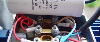
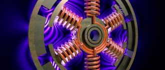
The relay cover has the following symbols:
- R/M – working (Main) – main winding;
- A/S – starting (Start) – auxiliary winding;
- L – line (Line) – phase of the supply network.
When the relay is turned over, a knocking sound is heard from the freely sliding contacts. When installing such a relay, it is necessary to strictly maintain the spatial orientation (the inscription “Top” should be on top), since otherwise the open contact will be constantly closed.
By checking the current starting relay contacts between sockets A/S, P/M, L, A/S with an ohmmeter, the device should detect an open circuit, since the relay contacts are open. Between the P/M and L sockets, the resistance will be close to 0, since the resistance corresponds to the coil, the winding of which uses thick wire. It is designed to pass starting current.
If the relay is installed in an inverted position (Fig. 53.23), its contacts will remain permanently closed, and the starting winding cannot be turned off. In this case, there is a danger of rapid burnout of the electric motor.
Let's consider the operation of the starting relay in the absence of voltage (Fig. 53.24). When voltage is applied, current will flow through the thermal protection relay to the main winding and relay coil. Since contacts A/S and L are open, the starting winding is de-energized, and the engine does not start, this causes a sharp increase in current consumption. An increase in the starting current leads to a decrease in the voltage on the relay coil, which is enough for the core to be drawn into the coil, the contacts A/S and L are closed and the starting winding is thus energized.
The impulse received from the starting winding starts the engine and as the speed increases, the current consumption decreases. At the same time, the voltage on the relay coil (between L and R/M) decreases. When the motor has reached 80% of its power, the voltage between L and P/M will be insufficient to hold the core inside the coil, the contact between A/S and L will open, which will cause the starting winding to turn off.
With this circuit, the starting torque on the motor shaft will be small, due to the absence of a starting capacitor in it. Let us recall that the capacitor serves to increase the starting torque and provides the necessary amount of phase shift between the current in the main and starting windings. Thus, this scheme is used only in engines of low power and low torque on the shaft.
If we are talking about low-power refrigeration compressors (capillary tubes are used as an expansion device), then the engine starts with a small moment of resistance on the shaft.
In order to increase the starting torque, it is necessary to install a starting capacitor (Cd) in series with the starting winding. For this purpose, the current relay is produced with four sockets (Fig. 53.25). When measuring the readings of this relay between sockets M and 2, the resistance will be close to zero (equal to the resistance of the relay winding). In the normal position of the relay, the resistance readings between 1 and S will be close to infinity, and in the inverted state (cover down) - zero.
If there is a need to replace a current relay, then the new one must have the same index as the faulty one.
Design and purpose of capacitors
This element of the electrical circuit consists of two plates (plates). The plates are positioned relative to each other so that there is a gap between them. When a capacitor is connected to an electric current circuit, charges accumulate on the plates. Due to the physical gap between the plates, the device has low conductivity.
Attention! This gap can be air or filled with a dielectric. The following dielectrics are used: paper, electrolyte, oxide films.
The main feature of such a two-terminal network is the ability to accumulate electric field energy and instantly transfer it to the load (charge and discharge).
Part device
The first prototype of the container was the Leyden jar, created in 1745 in the city of Leiden by the German von Kleist. The jar was lined with copper foil inside and out. This is how the idea of creating covers came about.
Leyden jars connected in parallel
The graphic designation of a two-terminal network on diagrams and drawings is two vertically located lines (like plates) with a gap between them.
Designation on diagrams
Specifics of circuits with capacitors
When selecting the types of switching on of electric machines using starting and working two-terminal circuits for a 220 volt network, the following are distinguished:
- inclusion in the “triangle”;
- star connection.
For your information. What are the differences between starting and working two-terminal networks? “Starting” are elements that are used only for starting, and “working” are those that are constantly used in operation.
Schemes for connecting to a single-phase network
When installing a single-phase motor in a single-phase line, it is started using an additional winding. Such a motor has three outputs:
- from the working coil;
- from additional;
- common output for both windings.
When there is no marking, the coils are “ringed” by a tester to determine the correct connection.
Assembly type "Triangle"
To connect an asynchronous three-phase machine to a single-phase line, it is possible to use a delta connection. The starting capacitance is turned on according to the diagram.
Assembly type "Star"
The principle of assembling the starting circuit of a 3-phase motor, the windings of which are connected by a star, is similar. When it is possible to independently make such a connection of the windings, it is carried out on the terminal block.
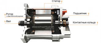
Centrifugal switch
A centrifugal starting winding switch is mounted on the rotor. [17]
Tachogenerators allow the attachment of centrifugal switches type RIS, with the exception of tachogenerators type PT-22/1 with a rotation speed of 2400 rpm, PT-32/1 with a rotation speed of 200 rpm and PT-42 with a rotation speed of 400 - 200 - 100 rpm / min. [18]
Asynchronous motors are equipped with a centrifugal switch, which, after starting the motor, turns off the starting winding. The electric motor is mounted on special insulated washers. The tension of the drive belt is adjusted by moving the engine on the frame. After this, the engine is secured. Washing machines equipped with additional commutator motors have an interference suppression device - a special circuit based on constant-capacity capacitors. [19]
Using Electrolytic Capacitors
To start operation of a three-phase motor from 220V, the starting capacitor must have a large capacity. To move the shaft of an engine with a power of 3 kilowatts, 2100 uF of capacitance is needed. To select such a value of C, you will need a whole battery of non-polar components. Electrolytic two-terminal networks (electrolytes) have a larger capacity with smaller dimensions. But their inclusion in the alternating current circuit for a long time is unacceptable.
Carefully. When the container is connected for a long time, the electrolyte boils and the element explodes.
Wiring diagram for an electrolytic cell to start the engine
Connecting an electric motor with your own hands
How to choose a capacitor for a single-phase motor is already clear. The selection of capacitors for a three-phase motor is considered. How to practically mount a circuit to start an engine, what is necessary for this?
The circuit consists of the following components:
- engine (up to 3 kW);
- capacitors: starting and running, which differ in capacity;
- 220 V PVS start button.
Why do you need a start button? For short-term connection of an electrolytic two-terminal network and starting the motor rotation. The circuit is assembled according to the diagram in the picture below. All connections are made using bolted clamps. Bare sections of wires are subject to mandatory insulation.
Practical connection diagram
The use of starting and operating capacitors makes it possible to start motors in any circuit. The capacity of the two-terminal circuits should be sufficient to start rotation and stable operation under load. It is preferable to use new parts.
Chipguru
- Forum Forum Rules
- Rules for Editors
- Competition rules
- Flea Marketer's Guide
- Educational program on the forum Change the color of the forum
- How to insert photos
- How to insert links
- How to embed a video
- How to indicate offtopic
- How to quote
- Stitching messages
- Theme icons
- Subscribe to topics
- Auto-subscribe to topics
- Metal
- Bearings
- Steel grades and alloys
- Thread diameters
- Unanswered topics
- Active topics
- Search
- our team
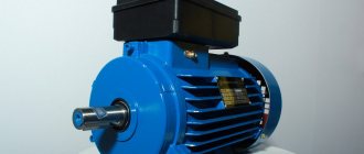
Features of a three-phase motor
Asynchronous electric motors with three stator windings predominate in various agricultural sectors. They are used to drive ventilation devices, remove manure, prepare feed, and supply water. The popularity of such motors is due to a number of advantages:
- simplicity of structure;
- reliability in operation;
- when connected in normal mode, expensive and scarce devices are not used;
- the number of technical services is small.
Basic parameters of capacitors
The capacitance of a capacitor characterizes the energy that a capacitor is capable of accumulating, as well as the current that it is capable of passing through itself. Measured in Farads with a multiplying prefix (nano, micro, etc.). The most commonly used values for run and start capacitors range from 1 μF to 100 μF. The rated voltage of a capacitor is the voltage at which the capacitor is able to operate reliably and for a long time, maintaining its parameters.
Well-known capacitor manufacturers indicate on its body the voltage and the corresponding guaranteed operating time in hours, for example:
- 400 V – 10,000 hours;
- 450 V – 5000 hours;
- 500 V – 1000 hours.
Compressor. Disabling start-up capacitors based on line pressure
Compressor. Disabling start-up capacitors based on line pressure
Post #1 » Oct 18, 2016, 11:58 am
Good afternoon, guys. I'm trying to assemble a compressor, based on a compressor from a MAZ car, 3F motor, in a 220 socket.. In order not to make unnecessary fuss, I came up with the idea of controlling the starting capacitor by means of the presence/absence of pressure in the line between the compressor and the receiver. All pneumatic fittings will be used from the deceased Chinese, and the unloading valve will naturally be used. those. there is no pressure, the starting capacitor is connected, the compressor began to pump air, the pressure increased, the condenser turned off. As a sensor I plan to use a minimum oil pressure sensor from the car (there is 0.4 bar)
Do you think it will work? Naturally, the capacitors will be switched through a relay or starter.
Compressor. Disabling start-up capacitors based on line pressure
Post #2 ROW » Oct 18, 2016 12:26 pm
Compressor. Disabling start-up capacitors based on line pressure
Post #3 Korben Dallas » Oct 18, 2016 12:28 pm
Compressor. Disabling start-up capacitors based on line pressure
Post #4 VVKV » 18 Oct 2016, 12:38
Compressor. Disabling start-up capacitors based on line pressure
Post #5 » Oct 18, 2016, 1:14 pm
The logic is simple: 1. everything is turned off, there is no pressure in the line from the compressor to the receiver, the starting capacitors are “connected”. 2. The pressure in the receiver has dropped, the pressure switch turns on the compressor motor, and the starting capacitors are still connected. 3. The engine has started and begins to pump into the main line, the pressure in it has risen, the sensor has tripped, and the capacitors have turned off. 4. The pressure in the receiver has risen to the set value, the pressure switch turns off the engine and relieves pressure from the line between the compressor and the receiver. The pressure sensor “connects” the capacitors for the next start.
Checking the starting and running capacitors
You can check the capacitor using a capacitor capacitance meter; such devices are produced both separately and as part of a multimeter, a universal device that can measure many parameters. Let's consider checking with a multimeter.
- de-energize the air conditioner
- discharge the capacitor by short-circuiting its terminals
- remove one of the terminals (any)
- We set the device to measure the capacitance of capacitors
- We lean the probes against the terminals of the capacitor
- read the capacity value from the screen
All devices have different designations for the capacitor measurement mode; the main types are shown below in the pictures. In this multimeter, the mode is selected by a switch; it must be set to Fcx mode. Insert the probes into the sockets marked Cx. Switching the capacitance measurement limit is manual. Maximum value 100 µF.
Checking the starting and running capacitors.
Subscribe to the newsletter
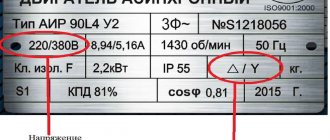
Three-phase motors are designed for an operating voltage of 380 V. But such voltage is not always available in everyday life. Therefore, a problem arises: how to connect an electric motor through a capacitor to a household network? The most acceptable and widely available method is to use a phase-shifting capacitor. In this mode, 50–60% of the nominal power can be achieved. Note that not all asynchronous motors will work equally well when connected to a single-phase network. The engines most adapted to these conditions are those with a squirrel-cage rotor made in the form of a double cage.
Optimal operation of the electric motor is achieved only if the capacitance of the capacitor changes as the rotation speed increases. In practice it is very difficult to implement this requirement. In this regard, two-stage motor control is adopted. Starting is carried out using two capacitors (starting - Sp and working - Wed). Then, when the desired rotation speed is reached, the starter must be turned off. Its main function is to increase the starting torque.
The calculation of a capacitor for an electric motor can be done in this way. The calculation formula looks like: Ср = К*(In/U). The following notations are used here:
current strength (nominal) - In (A);
voltage (nominal) - U (V);
K is a dimensionless coefficient.
The value of K is determined by how the engine is turned on. K = 2800 when the engine is turned on in a star configuration. If it is switched on according to the “triangle” circuit, then the value K = 4800 (Fig. 1).
It is recommended to choose paper capacitors for starting an electric motor, in particular:
- paper, sealed, in a metal case, marked KBG-MN (Fig. 2);
- paper, heat-resistant, symbol BHT;
- metal-paper, frequency, MBGCH.
If it is necessary to change the direction of rotation of the motor, it is enough to swap the wires connected to the terminals of the capacitor. It is better to start an electric motor using a capacitor using a delta circuit. In this case, you can achieve maximum output power (up to 70%).
As an example, consider the AO2 engine. Its rated power is 2.2 kW, rotation speed is 1420 rpm. To start it in idle mode (or when there is a load), you will need 2 capacitors: the first with a capacity of 230 μF (working) and the second with a capacity of 150 μF (starting).
To ensure reliable operation of the electric motor, starting capacitors are used.
The greatest load on the electric motor occurs at the moment of its start. It is in this situation that the starting capacitor begins to work. We also note that in many situations the start-up is carried out under load. In this case, the load on the windings and other components is very high. What design allows you to reduce the load?
All capacitors, including starting capacitors, have the following features:
- as a dielectric . In this case, an oxide film is often used, which is applied to one of the electrodes.
- Large capacity with small overall dimensions is a feature of polar storage devices.
- Non-polar ones are more expensive and larger, but they can be used without regard to polarity in the circuit.
This design is a combination of 2 conductors that are separated by a dielectric. The use of modern materials can significantly increase the capacity indicator and reduce its overall dimensions, as well as increase its reliability. Many with impressive performance indicators have dimensions of no more than 50 millimeters.
Which type to use
The requirements for capacitors for starting electric motors are simple:
- the capacity is sufficient to start the engine;
- the rated voltage is selected 10-15% higher than the connected one;
- The two-terminal network must work with the applied type of current.
There are small nuances for electric machines that differ in operating principles.
For operation with a three-phase electric motor
In this case, the part carries out a phase shift in the winding of an asynchronous machine, and its capacitance must be high. Creation of a starting torque and further operation under load require a more precise selection of this element characteristic.
Switching on with a single-phase electric motor
Starting capacitors are used here to connect an additional winding. It is designed to start the motor and can be turned on either permanently, through a two-terminal network, or briefly without it.
Part selection features
The selected starting capacitors correspond to the applied voltage. The size of their capacity should not allow the engine to overheat during operation and should be easy to start when turned on. There are no particular difficulties with the selection of elements.
Advantages of SCP
Compared to other starting schemes for asynchronous electric motors, the soft starter provides the greatest reduction in the amplitude of the starting current.
In addition, such devices have the following advantages:
- Extending the service life of the engine and process equipment. The soft starter reduces the heating of windings and contacts, and also eliminates dynamic shocks.
- Significant reduction in costs for electric drive hardware.
Installing soft starters allows you to save on protection circuits and install less powerful switching devices. - Reducing the load on the power grid.
Soft starters reduce current surges and prevent voltage drops in electrical networks. This is especially true when the power of transformers is limited and when autonomous power supplies are used. - Improving production safety.
A smooth start and acceleration will reduce injuries in the event of equipment breakdowns associated with jerks during startup, the likelihood of water hammer, and other emergency situations. - Reducing induced interference at start-up.
Soft starters reduce the intensity of the magnetic field when starting an electric motor. Soft starters make it possible to eliminate the need for filters for control cables. - Low cost.
Soft starters are several times cheaper than frequency converters of the same power. Soft starters are advantageous to use under constant load of equipment in conditions where limiting inrush currents and starting torque are the main requirements.
SCPs also replace mechanical brakes and kinematic stopping devices. In addition, soft starters allow the use of asynchronous motors with a squirrel-cage rotor instead of expensive electrical machines with improved starting characteristics or a wound rotor.
The choice of starting scheme is carried out based on an analysis of the equipment requirements and the characteristics of the electrical network.
Capacity size: working and starting
The specific capacity of these elements can be calculated using an online calculator on the Internet. The calculation is done independently using formulas.
For the trigger element
There are two known formulas for determining the capacity of a starting two-terminal network:
- for the “star” circuit – Cп = 2800*I/U;
- for the “triangle” circuit – Cп = 4800*I/U.
The rated current is calculated using the expression:
Here:
- P – motor power;
- U – network voltage;
- η – efficiency;
- cosϕ – power factor.
For work item
You can select a working capacitor based on the following calculation:
A running and stable engine requires the use of a working tank to rotate under load.
Connection diagrams for single-phase asynchronous motors
With starting winding
To connect a motor with a starting winding, you will need a button in which one of the contacts opens after switching on. These opening contacts will need to be connected to the starting winding. In stores there is such a button - this is PNDS. Its middle contact closes for the holding time, and the two outer ones remain in a closed state.
Appearance of the PNVS button and the state of the contacts after the “start” button is released"
First, using measurements, we determine which winding is working and which is starting. Typically the output from the motor has three or four wires.
Consider the option with three wires. In this case, the two windings are already combined, that is, one of the wires is common. We take a tester and measure the resistance between all three pairs. The working one has the lowest resistance, the average value is the starting winding, and the highest is the common output (the resistance of two windings connected in series is measured).
If there are four pins, they ring in pairs. Find two pairs. The one with less resistance is the working one, the one with more resistance is the starting one. After this, we connect one wire from the starting and working windings, and bring out the common wire. A total of three wires remain (as in the first option):
- one from the working winding is working;
- from the starting winding;
- general.
We work further with these three wires - we use them to connect a single-phase motor.
With all these
- Connecting a single-phase motor with a starting winding via the PNVS button
connecting a single-phase motor
We connect all three wires to the button. It also has three contacts. Be sure to place the starting wire on the middle contact (which closes only during the start), the other two - on the outer ones (arbitrarily)
We connect a power cable (from 220 V) to the extreme input contacts of the PVNS, connect the middle contact with a jumper to the working one (note! not to the common one). That's the whole circuit for switching on a single-phase motor with a starting winding (bifilar) through a button
Condenser
When connecting a single-phase capacitor motor, there are options: there are three connection diagrams and all with capacitors. Without them, the engine hums, but does not start (if you connect it according to the diagram described above).
Connection diagrams for a single-phase capacitor motor
The first circuit - with a capacitor in the power supply circuit of the starting winding - starts well, but during operation the power it produces is far from rated, but much lower. The connection circuit with a capacitor in the connection circuit of the working winding gives the opposite effect: not very good performance at start-up, but good performance. Accordingly, the first circuit is used in devices with heavy starting (concrete mixers, for example), and with a working condenser - if good performance characteristics are needed.
Circuit with two capacitors
There is a third option for connecting a single-phase motor (asynchronous) - install both capacitors. It turns out something between the options described above. This scheme is implemented most often. It is in the picture above in the middle or in the photo below in more detail. When organizing this circuit, you also need a PNVS type button, which will connect the capacitor only during the start time, until the motor “accelerates”. Then two windings will remain connected, with the auxiliary winding through a capacitor.
Connecting a single-phase motor: circuit with two capacitors - working and starting
When implementing other circuits - with one capacitor - you will need a regular button, machine or toggle switch. Everything connects there simply.
Selection of capacitors
There is a rather complex formula by which you can calculate the required capacity accurately, but it is quite possible to get by with recommendations that are derived from many experiments:
- The working capacitor is taken at the rate of 70-80 uF per 1 kW of engine power;
- starting - 2-3 times more.
The operating voltage of these capacitors should be 1.5 times higher than the network voltage, that is, for a 220 volt network we take capacitors with an operating voltage of 330 V and higher. To make starting easier, look for a special capacitor for the starting circuit. They have the words Start or Starting in their markings, but you can also use regular ones.
Changing the direction of motor movement
If, after connecting, the motor works, but the shaft does not rotate in the direction you want, you can change this direction. This is done by changing the windings of the auxiliary winding. When assembling the circuit, one of the wires was fed to the button, the second was connected to the wire from the working winding and the common one was brought out. This is where you need to switch the conductors.
{SOURCE}
Communities › Garage Equipment and Tools › Blog › Starting the Compressor
Problem…
After purchasing a compressor, I encountered the problem of starting it in the garage. And this is not due to a malfunction of the compressor, but to the voltage in the garage - there is electricity in it so that the lights are on. At first, after several attempts to turn it on and off, the compressor started when it “warmed up”. Then it started to turn on only when the lights were on outside, and then it refused to start at all...
Compressor Fiac CCS 50/338 M
Receiver volume 50 l Weight 55 kg Power 2.25 kW Voltage 220 V Capacity 330 l/min Operating pressure 10 bar
The search for the causes of the problem showed that when the asynchronous motor starts, the starting current increases, but the local network is not able to provide this power. There is an option to install a voltage stabilizer, but it must be powerful enough to withstand load surges. I decided to try this option and for my 2.5 kW compressor I took the RUCELF SDW-10000-D stabilizer with a nominal power of 10 kW. The situation improved - the compressor began to start again after several attempts to turn it on and off, but only dances with the stabilizer were added - when the compressor entered the “mode” it was switched off due to protection. After “warming up” the compressor, it started without “dancing”. But this is also not what is needed.
There is another option...
Since the three-phase motor of my compressor is connected to a single-phase network by connecting the third winding through a phase-shifting capacitor, in order for the electric motor to start “easier”, the capacitance of the capacitor must change: - starting - with a starting capacitor (due to high starting currents), - after acceleration - its starting capacitor the capacitor is disconnected, leaving only the working one. If the starting capacitor is not disconnected, the engine will overheat and burn out. I decided to try this option too.
Scheme.
The general scheme is quite simple.
When the compressor starts, the starting capacitor Sp is connected in parallel to the working capacitor Cp - in the diagram there is an “Acceleration” button and after a certain time it turns off. In order to automate the process, a time relay is used. We connect it so that after turning on the compressor it turns off after a set time and turns off the starting capacitor (see diagram below).
I found recommendations on the main parameters of such a circuit: - operating time of the starting capacitor - about 3 seconds; — the capacity of the starting capacitor is 2...2.5 times greater than the working one; - the permissible voltage of the starting capacitor must exceed 1.5 times the network voltage - for example, 450 V; - the starting capacitor must be shunted with a resistor R1 with a resistance of 200...500 kOhm, through which the remaining electrical charge will “drain”.
The compressor is equipped with a motor: Asynchronous, type 80 Voltage 230 V, 50Hz Speed 1
2850 rpm Current 12 A cos = 0.95 Power 2.5 kW Capacitor 60 uF
Taking this information into account, I purchased the necessary components.
Necessary:
NOTE: Below are the prices I remember. — starting capacitor DPS-0.45-120 (120 μF, 450 V) – price 880 rubles; NOTE: There are smaller starting capacitors, but I didn’t have any luck with it. During the test, it was my fault that it became swollen.
— relay ST6P-4, operating voltage 220V, maximum current on contacts 5 A;
If space allows, you can use a relay block and get rid of soldering.
— resistor 200...500 kOhm power 2 W; - switch; - wires; — terminals — for connection to the capacitor; — heat shrink/cambric/insulating tape; - frame; — two clamps (diameter about 80 mm).
Tool:
- soldering iron; - screwdriver; - knife; - file; - drill; — drill with a diameter of 8 mm; — key / head 12-13; — “crimper” – for crimping terminals.
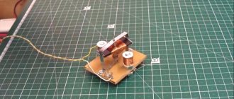
First, we assemble the circuit - we connect an external capacitor and a relay and put it all into the case.
In order to be able to turn off the circuit, I included a switch in the circuit.
Since the capacitor “turned out” to be very large and with a screw for fastening - I chose it as the basis of the design - I secured the housing with the relay on it using clamps. To do this, I slightly modified the body ears.
Installation:
The entire structure is attached to the compressor with a capacitor screw - to do this, drill a hole with a diameter of 8 mm in a suitable place on the base of the compressor.
Connection:
The connection is quite simple - you need to connect three wires: 1. Connect 2 wires to the working capacitor. — remove the capacitor - it is located under the engine and is secured with a nut;
— remove the protective cap and disconnect the wires from the working capacitor; — we stretch the wires from the external unit and connect them into the gap between the capacitor and its wires from the engine; NOTE: It’s more convenient when the color of the wires of the external capacitor and the working one match - you don’t need to think when connecting what to connect where - for me it’s blue and red. — install the working capacitor in place. 2. Connecting the control wire to the Pressure Switch: - unscrew the screw and remove the cover; — we insert the wire from the external unit through the input hole and connect it to the contact (with the brown wire);
— put the lid back. Set the delay time on the relay to 3 seconds and turn on the compressor.
Below is a video example of how the compressor behaves with the external starting capacitor turned off and on.
Calculation of required capacity
When choosing a capacitor, it is necessary to prevent a situation in which the phase current exceeds its rated value. Therefore, the calculations must be approached very carefully - incorrect results can lead not only to capacitor failure, but also to burnout of the motor windings. In practice, to start small-power motors, a simplified selection is used based on the considerations that for every 100 W of motor power, 7 μF of capacitance is required when connected in a triangle. When connecting the winding in a star, this value is halved. If a three-phase motor with a power of 1 kW is connected to a single-phase network, then a capacitor with a charge of 70-72 μF is required when the windings are connected in a triangle, and 36 μF in the case of a star connection.
It will be interesting➡ What is a variable capacitor
The required capacity value for operation is calculated using formulas.
With a star connection:
Wed=2800 I/U
If the windings form a triangle:
Wed=4800 I/U
I is the rated current of the motor. If for some reason its value is unknown, you must use the formula for calculation:
I = P / (3 U).
In this case, U = 220 V when connected by a star, U = 380 V when connected by a triangle.
P is power, measured in watts.
When starting an engine with a significant load on the shaft, it is necessary to turn on the starting gear in parallel with the working tank.
Its value is calculated using the formula:
Sp=(2.5÷3.0) Avg
The starting capacity should exceed the operating capacity by 2.5 - 3 times.
Material on the topic: all about the variable capacitor.
The correct choice of voltage value for the capacitor is very important. This parameter, as well as capacity, affects the price and dimensions of the device. If the mains voltage is greater than the rated value of the capacitor, the starting device will fail. But you shouldn’t use equipment with too much voltage either. After all, this will lead to an ineffective increase in the dimensions of the capacitor bank. The optimal capacitor voltage value is 1.15 times higher than the network voltage: Uk = 1.15 U s.
Very often, when connecting a motor with three windings to a single-phase network, capacitors of the KGB-MN or BGT type (heat-resistant) are used. They are made of paper. The metal case is completely sealed. Has a rectangular appearance. It must be taken into account that the permissible voltage and capacitance values indicated on the device are indicated for direct current. Therefore, when operating on alternating current, it is necessary to reduce the capacitor voltage by 2 times.
Calculation of the required capacity.
Adjusting the compressor pressure
As mentioned above, after creating a certain level of air compression in the receiver, the pressure switch turns off the unit’s engine. Conversely, when the pressure drops to the switching limit, the relay starts the engine again.
Important! By default, relays, both single-phase devices and units operating from a 380 V network, already have factory settings. The difference between the lower and upper engine start threshold does not exceed 2 bar. It is not recommended for the user to change this value.
But often situations that arise force you to change the factory settings of the pressure switch and adjust the pressure in the compressor at your discretion. You can only change the lower switching threshold, since after changing the upper switching threshold upward, the air will be released by the safety valve.
Pressure adjustment in the compressor is carried out as follows.
- Turn on the unit and record the pressure gauge readings at which the engine turns on and off.
- Be sure to disconnect the device from the power supply and remove the cover from the pressure switch.
- After removing the cover, you will see 2 bolts with springs. The large bolt is often designated by the letter “P” with the signs “-” and “+” and is responsible for the upper pressure, upon reaching which the device will be turned off. To increase the level of air compression, turn the regulator towards the “+” sign, and to decrease it, turn towards the “-” sign. First, it is recommended to make half a turn with the screw in the desired direction, then turn on the compressor and check the degree of pressure increase or decrease using a pressure gauge. Record at what indicators of the device the engine will turn off.
- Using a small screw you can adjust the difference between the on and off thresholds. As mentioned above, it is not recommended that this interval exceed 2 bars. The longer the interval, the less often the device’s engine will start. In addition, the pressure drop in the system will be significant. Setting the on-off threshold difference is done in the same way as setting the upper on-off threshold.
In addition, you need to configure the gearbox if it is installed in the system. It is necessary to set the compression level on the gearbox to a level that corresponds to the operating pressure of the pneumatic tool or equipment connected to the system.