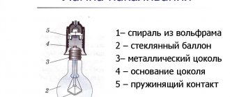
Servo motors, also called servo motors or servo motors, are widely used in applications that require precise control, such as robots, automated equipment, robotic arms, etc. However, the scope of application of servo motors is not limited to just these areas - they can be used in many other applications.
In this project we will connect the servomotor to the ATmega16 microcontroller (AVR family) using the Atmel Studio 7.0 software environment. The servomotor operates from a voltage of 4.8-6V. We can control (control) the rotation angle and direction of rotation of the servomotor using PWM (pulse width modulation) signals. It should be noted that servos cannot rotate a full 360 degrees and are not used where continuous rotation of the motor is required. Typically, the rotation angle for them ranges from 0-180 degrees or from (-90) to (+90) degrees.
General principles of operation of servomotors (servomotors)
Servomotors include a small DC motor, a gearbox, and a control circuit containing a variable resistor that allows the servomotor output shaft to be positioned at a specific angle. Therefore, servo motors are very convenient for projects where very fast and relatively accurate movement of any working element is required.
Types of Servo Motors
Servo motors are often used in radio-controlled car models to turn steering wheels or in radio-controlled airplane models to turn control surfaces (rudders). The following figure shows two servo motors of different sizes.
The servo motor on the right is a so-called standard servo motor. This is the most common type of servo motor. Such servomotors quite often have the same dimensions and mounting distances between the holes. The much smaller (and lighter) servo motor on the left is designed for aircraft applications. These servos are called 9g servos.
Servos with higher quality and higher torque have a gearbox with metal gears rather than nylon. Most servos operate on a nominal supply voltage of about 5 V, with an acceptable supply voltage range of 4 to 7 V. Connection to amateur servos is usually made through wires ending in a 3-pin connector: power +, power - and control signal.
Large and sometimes very powerful servos are also available for use, but they are not as standardized as hobbyist low-power servos.
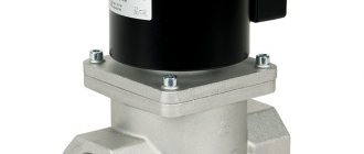
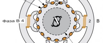
Servo drive device
The servo drive (see figure) consists of a direct current electric motor that drives a gearbox that reduces the speed of rotation of the motor and, at the same time, increases the torque on the shaft. To control the position of the output shaft, it is connected to a position sensor (usually a variable resistor). To control the power and direction in which the servo motor turns, the control circuit uses an input signal from the position sensor in combination with a control signal to set the desired position.
The control unit, having received the value of the desired shaft position through the control signal, subtracts from it the value of its actual position and generates an “error signal”, which can be positive or negative. This "error signal" is applied to power the motor, causing it to change the position of the shaft in the desired direction. The greater the difference between the desired and actual output shaft position, the faster the motor will turn to the desired position. The closer to zero the error (mismatch) value becomes, the less power the motor receives.
Servo motor control
The control signal to the servo motor is not a voltage, as you might expect, but a pulse width modulation (PWM) signal. This signal is standard for all amateur servos and looks as shown in the following figure.
The servo motor waits for a control pulse to arrive every 20 ms. A 1.5 ms pulse will set the servomotor to the center position corresponding to a 90° rotation of the output shaft. Shorter pulses of 1.0 ms will set the output shaft to the initial position of 0°, and pulses of 2.0 ms will set the output shaft to the extreme position of 180°. In reality, this range may be slightly less than a full 180°, without the pulses being shortened at one end and lengthened at the other. It is also not uncommon for a situation where an impulse of 0.5 ms is needed for 0°, and 2.5 ms for 180°.
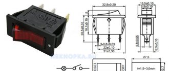
Assignment of servomotor contacts
Shown in the following figure. I think everything is simple and clear here.
1. Red = Positive supply voltage (4.8V to 6V) 2. Brown = Ground 3. Orange = Control Signal (PWM Pin)
Servo drive control according to a given program
When the sequence of actions is known in advance, you can write it into an array and then transfer it to the servo drive one by one.
Let's put together a diagram:
Connecting one servo drive to Arduino
For programmatic control, you can use the following program:
// Software control of the servo drive // (c) Roman Isakov, 2020 // (c) LabData.ru #include #define servo_pin 8 // Connector for connecting a servo #define servo_speed 500 // Command processing speed uint32_t servo_T = 0; // Service variable int pos = 0; // Current command number int prog[] = {180, 100, 80, 90, 85, 90, 85, 90, 70, 60, 50, 40, 20, 10}; // Servo commands Servo servo1; // Servo object void setup() { servo1.attach(servo_pin); // Connect the servo servo_T = millis(); } void loop() { int N = sizeof(prog)/sizeof(int); // number of array elements prog if (millis() - servo_T >= servo_speed) { // Software timer interrupt servo_T = millis(); servo1.write(prog[pos]); // Sending a command to the server pos++; // Select the next command if (pos>=N) pos = 0; // If you reach the end, repeat again } }
Commands can be easily removed and added, the program itself will calculate their number.
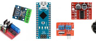
Required Components
- Microcontroller ATmega16 (buy on AliExpress).
- Programmer AVR-ISP (buy on AliExpress), USBASP (buy on AliExpress) or another similar one.
- Micro servomotor SG90 Tower Pro (buy on AliExpress).
- Quartz resonator 16 MHz (buy on AliExpress).
- Capacitor 100 nF (2 pcs.) (buy on AliExpress).
- Capacitor 22 pF (2 pcs.) (buy on AliExpress).
- Button.
- LED (buy on AliExpress).
- Bread board.
- Mounted conductors.
- Power supply with a voltage of 5 Volts.
Circuit operation
Connect all components as shown in the following figure.
The Atmega16 microcontroller has four PWM pins, we can use any of them. In this project we will use pin PD5 (OC1A) - we will connect it directly to the orange wire of the servomotor. The LED will be used to indicate power. It is also necessary to connect one button to the reset pin of the microcontroller in order to be able to reset it at any time. Connect the Atmega16 to a crystal oscillator. Our entire design will operate on 5V.
The fully assembled circuit will look like this (under the piece of paper there is a servomotor):
Servomotor control using AVR ATmega16
Like a stepper motor, a servo motor does not need any external driver such as ULN2003 or L293D. To control it, you only need a PWM modulation signal, which can be easily generated using a microcontroller of the AVR family. The torque of the servo motor used in our project is 2.5kg/cm, so if you need more torque, you will need to use a different servo motor.
In the general principles of operation of servomotors, we have already found out that the servomotor expects the arrival of a pulse every 20 ms, and the angle of rotation of the servomotor will depend on the duration of the positive pulse.
To generate the pulses we need, we will use Timer 1 of the Atmega16 microcontroller. The microcontroller is capable of operating at a frequency of 16 MHz, but we will use a frequency of 1 MHz since in our project it will be enough for the microcontroller to cope with the functions assigned to it. We set the prescaler to 1, that is, we get a scale of 1 MHz/1 = 1 MHz. We will use timer 1 in fast PWM mode (that is, Fast PWM Mode), that is, in mode 14 (Mode 14). You can use different timer modes to generate the sequence of pulses you need. You can find more information about this in the Atmega16 Official Datasheet.
To use Timer 1 in fast PWM mode, we will need the top value (TOP value) of the ICR1 register (Input Capture Register1). You can find the TOP value using the following formula:
fpwm = fcpu/nx (1 + TOP) This expression can be simplified to the following:
TOP = (fcpu / (fpwm xn)) – 1 where N = prescaler division factor fcpu = processor frequency fpwm = pulse repetition rate at the servomotor input, which is equal to 50 Hz
That is, we must substitute the following variable values into the given formula: N = 1, fcpu = 1MHz, fpwm = 50Hz.
Substituting all this in, we get ICR1 = 1999.
This means that in order to reach the maximum level, i.e. 1800 (rotate the servomotor axis by 180 degrees), it is necessary that ICR1 = 1999.
For a frequency of 16 MHz and a prescaler division factor of 16, we get ICR1 = 4999.
Controlling multiple servos using a sensor signal
If the control signal depends on some external factors, then you need to connect a corresponding sensor to the Arduino. In this example, an analog angle sensor (potentiometer). We will control two servos independently. The task is to monitor the voltage on the sensor and close one servo in one direction, and the other in the other. As if imitating a gate.
The connection diagram looks like this:
Connecting two servos and a sensor to Arduino
The algorithm is implemented in the Arduino program:
// Control of servos from the sensor // (c) Roman Isakov, 2020 // (c) LabData.ru #include #define servo_speed 200 // Setting the operating speed #define servo1_pin 8 // Output 1 servo #define servo2_pin 9 // Output 2 servos uint32_t servo_T = 0; #define DAT_pin A0 // Potentiometer input Servo servo1; Servo servo2; void setup() { servo1.attach(servo1_pin); servo2.attach(servo2_pin); servo_T = millis(); } void loop() { if (millis() - servo_T >= servo_speed) { servo_T = millis(); int DAT = analogRead(DAT_pin); // Receive an analog signal from the potentiometer servo1.write(map(DAT, 0, 1024, 90, 180)); // Convert the voltage level from 0..1024 to an angle from 90 to 180* and send it to 1 servo servo2.write(map(DAT, 0, 1024, 90, 0)); // Convert the voltage level from 0..1024 to an angle from 90 to 0* and send it to the 2nd server } }
By turning the potentiometer knob, the servos will move and begin to monitor the angle of rotation.