The implementation of the technological process involves the use of various equipment. In some cases, it is necessary to achieve synchronous and in-phase rotation of the axes of various devices. Sometimes, for some reason, a mechanical connection is not possible. Then, instead of a clutch, a synchronizer is used - a special sensor, thanks to which the required synchronization can be achieved. It is often part of special systems that need to be rotated at a certain angle at a distance. Selsyn operates in receiver and transmitter mode. It is worth understanding in detail what it is, how it works and where it can be used.
Types of synchronous communication
Before you begin to understand what selsyns are and how they function, it is worth getting acquainted with the existing types of synchronous communication. According to this parameter, systems are usually divided into asynchronous rotation and rotation systems. Each variety has its own characteristics.
Synchronized rotation
It consists of two identical asynchronous electric motors equipped with phase-wound rotors. The rotor windings are connected. The stator is connected to 380 V.
Synchronized rotation
The composition includes selsyns, the execution of which allows self-synchronization. Depending on the number of phases they are divided into:
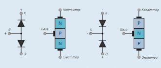
- Three-phase, whose design is fully consistent with asynchronous motors. The scope of use of such devices is limited due to the presence of a difference between the synchronization moments when the rotor rotates;
- Single-phase, similar in design to synchronous machines with minimal power. The field winding of such equipment only works when passing alternating current.
Watch the video at the end to understand the features of such a system.
What is the selsyn sensor used for and what is it?
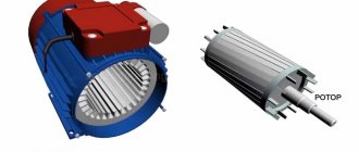
Anyone who would like to find out what a selsyn sensor is needs to familiarize itself in detail with its structure and principle of operation. To do this, first of all, you should understand that it is a type of electrical device that operates only on alternating current.
Additional information: The power of these devices varies from several units to hundreds of watts (but not more than a kilowatt).
The best way to understand what a selsyn sensor is is to understand its purpose. After familiarizing yourself with this issue, it turns out that it allows you to monitor the behavior of the moving parts of two devices located at a certain distance. This feature makes it possible to coordinate their rotation in the absence of a mechanical connection (electrically - via wires). In other words, selsyn sensors are electrically synchronized transmitting and receiving devices.
Synchronized turning systems: basic modes
Selsyns operate in two modes. Each of them has its own characteristics that must be taken into account when choosing equipment.
Indicator
If the equipment operates in this mode, it means that the rotor of the receiving device is connected to the driven axis. The diagram is relevant when choosing the minimum braking torque for the driven axle and placing an indicator arrow on it. The field windings are connected to a common circuit. Synchronizing devices are combined with a communication line.
The generated magnetic fluxes initiate the occurrence of EMF on the windings of all phases. A slight mismatch leads to the flow of electric current. Due to the flow, multidirectional moments are formed in the sensors and the receiving element of the synchronizer. With their help, it is possible to completely level out the mismatch angle.
The rotor located on the sensor is braked. As a result, the synchronization torque affects the mechanism that turns the drive axle. Thanks to this design, it is possible to ensure simultaneous rotation of the rotors of both connected elements to the same angle.
Transformer
The electrical signal that appears when the rotors are mismatched first goes to the amplifying part of the circuit. Next - onto the rotor of the actuator. The latter begins to turn the rotor of the receiving element and the driven axis until the existing difference is completely leveled. This mode is relevant when applying a braking torque of a sufficiently large value to the driven axis. That is, it helps to turn the mechanism.
The sensor winding is connected to the drive axle and connected to a 220 V power supply. An amplifier is used to supply voltage to the element that controls the engine control. The receiver winding is used to connect the synchronizer. A communication line is used to combine the synchronization windings of two synchronizers. A current is induced in the exciting winding, which creates an EMF in the synchronizing winding.
Current flows through both elements as their windings are connected. Magnetic pulses are formed in the receiving element. If the elements are mismatched, an emf appears in the winding under the influence of the flux. A voltage appears at the input, triggering a special amplifying element. From it, voltage is supplied to the stator, which belongs to the actuator. This leads to the fact that the driven axle begins to turn behind the receiver rotor. As the existing difference is eliminated, the voltage becomes zero and the rotation of the driven axis stops.
Features of the technology used and the design affect the magnitude of the error. These include:
- The difference between the parameters of the sensor and the receiving device;
- Uneven magnetic conductivity indicators;
- Lack of symmetry in the windings.
When transmitting an angle, errors inevitably occur. Their appearance is due to certain operating conditions. When the resistance value in the control network changes, the operating order of the synchronizers will change.
Scheme and principle of operation
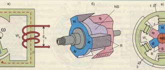
The proposed diagrams show various connection options (as a sensor, as a receiver and as a differential device).
After analyzing them, the following conclusions can be drawn:
- Both sensors and receivers are directly connected to the power supply with their stator windings.
- Their 3-coil rotor windings are united by linear electrical connections.
- Due to this inclusion, when the primary rotor is rotated by a given angle, a similar receiver assembly will rotate by the same degree.
- If you rotate the moving part of the sensor at a fixed speed, the corresponding receiver unit will rotate at the same frequency.
This effect is based on the principle of electromagnetic induction, the essence of which is the ability of a winding with alternating current to induce a field in a closely located coil (in the diagram - option “a”).
Important! Only a current varying in magnitude or phase (that is, alternating) can induce an external field.
The magnitude of the EMF induced in the stator coil depends on its distance from the rotor windings. In the case when the rotating parts of two devices (receiving and transmitting) are spaced at an equal distance from their stators, an interesting effect is observed. It consists in the fact that in this situation the currents in the rotor circuits are equal and opposite in direction, which leads to their resultant being zeroed. The consequence of this is the loss of torque on the shafts of both synchronizers (they are stationary)!
Design
The execution of selsyns dictates their operating principle. It is customary to highlight:
- contact ones, in which brushes and slip rings are used to connect the rotor winding and the external circuit;
- non-contact, which do not contain contact elements.
Each variety has its own distinctive features, which you should definitely familiarize yourself with in order to understand the principle of operation.
Contact
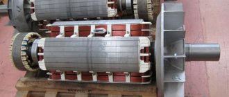
Contact motors are similar in design to asynchronous electric motors with a wound rotor and low power. They consist of a non-salient pole rotor and stator. Thanks to this, both windings are distributed. The rotor has an excitation winding. Two rings are used to supply electric current.
Some models already have a stator and rotor. This is their clear advantage. As a result, the synchronization torque increases. However, the contact elements in this case are a clear disadvantage.
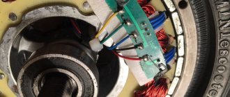
Contactless
No contact elements are needed to turn them on. Both windings are initially installed on the stator. The rotor has a characteristic cylindrical shape. For its manufacture, materials with ferrimagnetic properties are used. An aluminum layer divides the rotor into two poles.
Toroidal cores are located at the ends of the selsyns. Their internal part is located above the rotor. The outer one is connected to the rods of the external magnetic circuit. Electrical steel sheets are used for the manufacture of cores. The single-phase winding of the device consists of two disk coils located on both sides of the stator between the cores and the synchronization winding.
During operation of the device, a pulse-type magnetic flux is closed. The three-phase synchronizing winding is connected at the stator. The position of the magnetic induction flux axis changes as the spatial position of the rotor changes. It occupies a different position relative to the synchronizing windings. The magnitude of the resulting EMF directly depends on the angle through which the rotor was able to rotate.
The disadvantage of such devices is the less efficient use of active materials. In addition, they are on average 50% heavier than their contact counterparts, due to large air gaps. Thanks to the latter, the magnitude of magnetizing currents increases.
Types of selsyn sensors
Any operating synchronizer includes such mandatory elements as a stator and a rotor, made in the form of windings with electromagnetic coupling. The following types of electrical devices are known, differing in the number of coils located in the stator and rotor. They can be represented by the following combinations:
In the latter case, the number of windings in both parts is completely the same.
According to their practical application (use in electronic auto-adjustment circuits), these devices are divided into the following types:
- sensor devices;
- synchronizers-receivers;
- differential type devices.
Content
Selsyns and systems for remote transmission of the angle of rotation are divided into two groups: three-phase power and single-phase.
Three-phase synchros
Three-phase synchronous synchronizers are used in systems where it is necessary to ensure in-phase and synchronous rotation of two motors (shafts) located at a distance from each other.
Single-phase synchros
Single-phase synchronizers can operate in two modes.
- Indicator mode. The selsyn sensor is forced to rotate to a certain angle, and the selsyn receiver is installed in the corresponding position.
- Transformer mode. The selsyn sensor is forced to rotate to a certain angle, and a voltage is generated at the output of the selsyn receiver, which is a function of the mismatch angle between them.
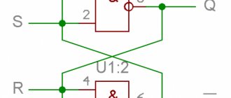
There are switching schemes for both modes:
- steam room (sensor and receiver),
- multiple (sensor and several receivers),
- differential (two sensors and a receiver).
Position sensor function
If you take and in some way (manually, for example) rotate the rotor of one of the devices at a certain angle, the balance of currents in its coil is disturbed. Due to the electrical connection, a similar mismatch of current balance is observed in the coils of the second device. As a result, a resultant appears that is different from zero, which leads to the formation of an e/m field and a moment of induction (rotational force). Under its influence, the movable assembly of the executive part will rotate to a state in which the balance of currents is completely restored. It is easy to understand that this state will correspond to the position of another device.
Auto-regulation
During automatic regulation, the receiver operates in transformer mode (in the diagram - “b”). Its rotor in this circuit is stationary, and the stator winding is completely disconnected from the network. An EMF is induced in it due to the currents flowing in its own rotor winding (their value is determined by the state of the first device). It follows that the magnitude of the EMF induced in the stator of the receiver completely depends on the angle of rotation of the moving part of the sensor.
Additional information: Due to the fact that the stator winding of the receiver is not connected to the network, the voltage phase in it is shifted by 90° relative to the stator coil of the sensor.
This circumstance is taken into account when calculating the output EMF (through a correction factor).
Differential device
This embodiment is used in cases where there is a need to determine the difference in the angular positions of two electrically connected devices (thus, the degree of their mismatch is revealed). In other words, selsyn sensors placed on different shafts are in this case compared by the speed of movement of their moving units, after which their mismatch is determined.
In this circuit, three coils from the two outermost devices are electrically connected to the corresponding windings of the rotor and stator of another (third) synchronizer, which is called differential (in the diagram - “c”). The angle of rotation of this third is determined as the difference in readings for two sensor devices.
Source