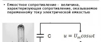
For theoretical calculations and practical application, it is often necessary to know the resistance of an electrical circuit. Based on this parameter, conclusions are drawn about the load power. With its help, the parameters of voltage dividers and other devices, individual parts of radio circuits are determined. After becoming familiar with thematic techniques, the identified and other tasks can be solved quickly and correctly.
Separate initial data can be obtained after measurements
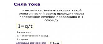
Definition
If you calculate the total resistance (Rtotal), you can find out the change in the main electrical parameters (current (I) and voltage (U)) when the circuit is connected to a specific power source. In the simplest version, it is enough to apply Ohm's law (I = U/R) and neglect the internal resistance of the battery.
At a voltage of U = 6.5 V, a current of I = 6.5/20 = 0.325 A will flow through the connected resistor R = 20 OM. Using the calculated parameter, you can find out the power using the classical formula:
P = I2 *R = U2/ R = 0.105625 * 20 = 2.11 W.
The resulting value will be useful for choosing a suitable passive element in the store’s assortment.
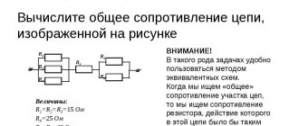
In practice, we have to solve problems with a large number of elements. The overall indicator is equivalent to the total resistance of the circuit. However, simple addition cannot obtain the correct result. Below are the technologies that perform correct calculations.
Basic terms and definitions
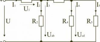
The figure explains the terminology used:
- i1, i2… i6 – currents in individual circuits;
- R1-R3 – passive elements (resistors);
- e1, e2 – typical designations of current sources (EMF);
- L and C – components with reactive characteristics (inductive and capacitive, respectively);
- branches are called with one current;
- the places where these chains are connected are nodes;
- the contours (indicated by Roman numerals I, II and III) show closed current paths along several branches.
Resistor element parameters
Current resistance: formula
When a graphic designation of a resistance element is applied to a diagram, some of its parameters are indicated on it.
Graphic designation of a resistor on diagrams
The main parameters and elementary characteristics include:
- nominal resistance value;
- temperature coefficient;
- maximum power dissipation;
- permissible operating voltage;
- noise factor;
- relative deviation from nominal value;
- element resistance to high temperature and humidity.
In drawings and diagrams, the resistor is designated by the letter R, followed by its serial number.
Features of calculations
To calculate the complete circuit, the internal resistance ( R int) of the source is taken into account using the formula:
Capacitance
I = E (EMF)/ (Req + Rin).
The existing circuit is transformed in order to simplify it according to the principles discussed above using equivalent resistances. Next, we use the classical relationships of electrical quantities, which are based on Ohm’s law.
Specific technologies are also used:
- loop currents;
- nodal potentials;
- equivalent generator;
- overlays
For your information. In addition to simplifying the circuits, standard methods for converting mathematical formulas are used. In some situations, it is more convenient to operate with fractional quantities, so you should update the relevant knowledge from the school curriculum in your own memory.
Mixed compound
What if the circuit has both parallel and series connections of resistors? In this case, the total resistance in sections is calculated. At the same time, you can redraw the diagram, replacing the component resistances with one “rectangle”, but putting the calculated result above it.
An example of calculating resistance for a mixed connection of resistors. We consider the original circuit as a set of parallel and serial connections
Step 1. Find the total resistance of resistors R3 and R4 connected in series:
R3-4 = 3 kOhm + 3 kOhm = 6 kOhm;
Step 2. Calculate the resistance of parallel connected resistors R2 and R3-4:
R2-4 = 3 kOhm * 6 kOhm / (3 kOhm + 6 kOhm) = 18 kOhm / 9 kOhm = 2 kOhm;
Step 3. Calculate the total resistance of series-connected resistors R1 and R2-4:
R1-4 = R1 + R2-4 = 1 kOhm + 2 kOhm = 3 kOhm.
Kirchhoff's postulates
These principles are used to calculate complex electrical circuits. Basic information about currents and voltages will help clarify control parameters in individual nodes. Using this information, the characteristics of individual functional components are adjusted. They are useful for determining the output signal level at certain points without the use of measuring equipment.
First postulate
Resistivity
According to the classical formulation, the sum (algebraic) of currents entering and leaving one node is determined by the expression:
i1 + i2 + … + in = 0.
This relationship is valid for any control point in the circuit where branches are connected. It does not matter which components are included in the individual circuits:
- reactive;
- passive;
- power supplies in any polarity.
For your information. It is assumed (for calculation) that the incoming/outgoing currents are positive/negative, respectively.
Second postulate
This rule determines the equality of the sums of voltages and emfs included in one circuit. For clarity, we can imagine a simple example with two resistors connected to a DC source. Using a multimeter, measure the voltages at the terminals:
- UR1 = 4 V;
- UR1 = 2.5 V;
- Ub = 6.5 V = UR1 + UR2.
The second rule is valid for all closed loops, mixed and complex connections. To check the calculations, you can sequentially sum up the difference in the potentials of the control points. If there are no additional generators (batteries) in the circuit, the result will be zero. Select the direction of bypassing the circuit corresponding to the positive current (entering the node). Shown above is a special case when the measurement results are added.
For your information. Kirchhoff's second postulate is used to calculate circuits connected to an AC power source.
Types of resistors
There are many types of resistors that are used in the electronics industry. Let's look at the main ones.
Fixed resistors
Constant resistors look something like this:
On the left we see a large green resistor that dissipates a lot of power. On the right is a small tiny SMD resistor that dissipates very little power, but still performs its function perfectly. You can read about how to determine the resistance of a resistor in the article marking resistors.
This is what a constant resistor looks like on electrical circuits:
Our domestic image of a resistor is depicted as a rectangle (on the left), and the overseas version (on the right), or as they say - bourgeois, is used in foreign radio circuits.
This is how power is marked on Soviet resistors:
Next, the power is marked using Roman numerals. V - 5 Watt, X - 10 Watt, L -50 Watt, etc.
What other types of resistors are there? Let's look at the most common ones:
20 watt glass with wire leads, 20 watt with mounting tabs, 30 watt in vitreous enamel, 5 watt and 20 watt with mounting tabs
1, 3, 5 watt ceramic; 5,10,25, 50 watt with conductive heat exchange
2, 1, 0.5, 0.25, 0.125 watt carbon structure; SMD resistors of standard sizes 2010, 1206, 0805, 0603,0402; SMD resistor assembly, 6,8,10 pin resistor assemblies for through-hole mounting, resistor in DIP package
Variable resistors
Variable resistors look like this:
On the diagrams they are indicated as follows:
Accordingly, domestic and foreign versions.
And here is their pinout (location of pins):
A variable resistor that controls voltage is called a potentiometer , and one that controls current is called a rheostat. Here lies the principle of a voltage divider and a current divider, respectively. The difference between a potentiometer and a rheostat is in the connection diagram of the variable resistor itself. In a circuit with a rheostat, a variable resistor connects the middle and outer terminals.
Variable resistors whose resistance can only be changed using a screwdriver or hex wrench are called variable tuning resistors . They have special grooves for adjusting the resistance (marked with a red frame):
And this is how trimming resistors and their connection circuits in rheostat and potentiometer mode are designated.
Thermistors
Thermistors are resistors based on semiconductor materials. Their resistance depends sharply on the ambient temperature. There is such an important parameter of thermistors as TCR - thermal coefficient of resistance. Roughly speaking, this coefficient shows how much the resistance of the thermistor will change when the ambient temperature changes.
This coefficient can be either negative or positive. If the TCR is negative, then such a thermistor is called a thermistor, and if the TCR is positive, then such a thermistor is called a posistor. For thermistors, as the ambient temperature increases, the resistance decreases. For posistors, as the ambient temperature increases, the resistance also increases.
Since thermistors have a negative coefficient ( NTC - Negative Temperature Coefficient - negative TCS), and posistors have a positive coefficient ( RTS - Positive Temperature Coefficient - positive TCS), they will be designated accordingly in the diagrams.
Varistors
There is also a special class of resistors that sharply change their resistance as the voltage increases - these are varistors.
This property of varistors is widely used to protect against overvoltage in a circuit, as well as against pulsed voltage surges. Let’s say our voltage “jumped”. The varistor “snapped” the whole thing and immediately sharply changed the resistance downward. Since the resistance of the varistor has become very small, all electric current will immediately begin to flow through it, thereby protecting the main circuit of the radio-electronic device. In this case, the varistor takes all the power of the pulse onto itself and very often pays for it with its life, then it burns out completely
In the diagrams, varistors are designated as follows:
Photoresistors
Photoresistors are also very popular. They change their resistance when you shine light on them. For these purposes, you can use both sunlight and artificial light, for example, from a flashlight.
In the diagrams they are designated as follows:
Strain gauges
The principle of their operation is based on stretching thin printed conductors. When stretched they become even thinner. It's like pulling out chewing gum. The more you stretch it, the thinner it becomes. And as you know, the thinner the conductor, the greater the resistance it has.
In the diagrams, the strain gauge looks like this:
Here is an animation of the strain gauge in action, borrowed from Wikipedia.
Well, as you guessed, strain gauges are used in electronic scales, as well as in various sensors where any pressure or force is applied.
Reactive components of loads
To figure out how to find the total resistance of a circuit under real-world conditions, you must consider the presence and corresponding influence of components with active and reactive characteristics. The first group includes:
- resistors (fixed and variable);
- connecting wires;
- heating elements (heating elements).
The conductivity of such products depends on the source material and the amount of impurities, cross-section and length, and temperature level.
Definition of superconductivity
As the current increases in a typical metal conductor, the collision of electrons with the molecular crystal lattice provokes the conversion of electrical energy into thermal energy. A clear example of such a process is a serial incandescent lamp. Up to 90% or more of the power consumption of such devices is wasted to heat the surrounding space.
The temperature effect on resistance is used to create sensors. The change in current in the corresponding circuit is recorded with a measuring device. After conversion into visual digital form, the results are displayed on the display.
Digital thermometer with remote sensor
Coils have inductive reactive characteristics. Connecting such a product shifts the phases of current and voltage. Electrical resistance (X L ) in this case strongly depends on the signal frequency ( f ), inductance ( L ):
ХL = 2π * f * L.
A special case of application is an interference limiter. Such circuits perform their functions due to strong resistance to current as the frequency increases (the rate of rise of the leading edge of the pulse).
For a load with capacitive properties, the following formula is used:
Xc = 1/ 2π * f * C.
A capacitor has these parameters. It also creates a phase shift and charges and discharges according to changes in the input signal.
Types of conductors
The conductivity of an electric current by a substance is associated with the presence of free charge carriers in it. Their number is determined by their electronic configuration. To do this, you need a chemical formula of the substance, with which you can calculate their total number. The value for each element is taken from the periodic table of Dmitri Ivanovich Mendeleev.
Electric current is the ordered movement of free charge carriers, which are affected by an electromagnetic field. When current flows through a substance, a stream of charged particles interacts with the nodes of the crystal lattice, and part of the kinetic energy of the particle is converted into thermal energy. In other words, the particle “hits” the atom and then continues moving again, picking up speed under the influence of the electromagnetic field.
The process of interaction of particles with nodes of the crystal lattice is called electrical conductivity or resistance of the material. The unit of measurement is Ohm, and it can be determined using an ohmmeter or calculated. According to the property of conductivity, substances can be divided into 3 groups:
- Conductors (all metals, ionized gas and electrolytic solutions).
- Semiconductors (Si, Ge, GaAs, InP and InSb).
- Non-conductors (dielectrics or insulators).
Conductors always conduct electric current because they contain free electrons, anions, cations and ions in their atomic structure. Semiconductors conduct electricity only under certain conditions, which affect the presence or absence of free electrons and holes. Factors affecting conductivity include the following: temperature, illumination, etc. Dielectrics do not conduct electricity at all, since there are no free charge carriers in their structure. When performing calculations, every radio amateur must know the dependence of resistance on certain physical quantities.
How to Calculate Total Circuit Resistance
For calculations, the rules, formulas, and verification steps presented above are used. It is recommended to first depict the diagram in a simplified form, with a complex combination of individual sections. Next, the equivalent resistances of the corresponding groups are calculated. If necessary, you can determine currents in circuits and find voltage values at control points.
Method 1 Serial connection
For such connections, the simple summation presented above is used:
Rtot = R1 + R2 + … + Rn.
The current in a closed circuit does not change. Checking when connecting a multimeter to any gap will show the same value. At the same time, each resistor with different values of the elements will have a different voltage drop. In accordance with Kirchhoff’s second postulate, the result of calculations is checked by addition:
Uakb = U1 + U2 + Un.
For your information. Using the above circuit, it is easy to calculate the voltage divider at a certain level for known operating parameters of the DC power supply.
Example calculations for a serial connection
Method 2 Parallel connection
In this connection option, it is convenient to operate with the parameter inverse to resistance - conductivity. However, it is permissible to use the following initial formula:
1/Rtot = 1/R1 + 1/R2 = 1/(1/R1 + 1/R2) = R1*R2/R1 + R2.
At the input node, the current is distributed among different circuits in proportion to the values of the corresponding resistors. The output is converted inversely. The calculations are checked according to the principles of Kirchhoff's first postulate.
Formulas and example for parallel connection
Method 3 Combined connection
Complex circuits are simplified. The parallel section is calculated separately. Next, an unbranched contour is created from successive elements.
Complex calculation
If necessary, you can transform the circuit from connecting resistors in a “triangle” to a “star” or vice versa. Below are formulas for calculating equivalent resistances in circuits after conversion.
Converting "star" to "triangle"
Method 4 Formulas Including Power
It is easy to find out what the result will be using any of the suitable formulas:
P = I2 *R = U2/ R.
The initial parameters are taken from preliminary calculations or determined by measurement. You can use calculation schemes with currents in circuits or voltages across individual resistors (groups of series-connected elements).
The magnitude of the voltage provided by the resistor element
The ideal element that converts electricity into another form of energy is called resistive. Electricity can be converted into light, heat or mechanical forms. The voltage across such an element depends on the potential difference at the ends of the resistor. This means that the greater the value of its resistance, the greater the voltage across it.
Changing a resistor characteristic such as resistance makes it possible to implement circuit solutions in various branches of radio engineering and electronics. When selecting elements, one should take into account the specific value of this quantity and the change in the current-voltage characteristic under different operating modes.
Order a TOE solution
- Metrology Electrical measurements
- Pigarev A.Yu. RGZ on electrical engineering and electronics in Multisim
- Theory of linear electrical circuits TLETs - Theory of linear electrical circuits of railway automation, telemechanics and communications: assignment for tests No. 1 and 2 with methodological instructions for fourth-year students of the specialty Automation, telemechanics and communications in railway transport - Test No. 1
- — Test No. 2
- — Electrical engineering and fundamentals of electronics: Guidelines and test assignments for part-time students of engineering and technical specialties of higher educational institutions / Sokolov B.P., Sokolov V.B. – M.: Higher. school, 1985. – 128 p., ill. – Test No. 1 Electric circuits
- — Artemenko Yu.P., Sapozhnikova N.M. Theoretical foundations of electrical engineering: A manual for course work MSTU GA 2009
Practical tasks:
- Work progress: 1) Connect the laboratory power supply (hereinafter, PSU) to the voltmeter (figure below). Using the regulator knob (located on the power supply), change the voltage on the voltmeter until it shows a value of 9 Volts. Since the internal resistance of the power supply is small (2) Assemble an electrical circuit consisting of an EMF source (laboratory power supply), a variable resistor, a constant resistor R, a voltmeter (multimeter in voltage measurement mode) and key K (open) according to the following diagram: 3 ) Using a variable resistor, set the internal resistance of the EMF source. To do this, take another multimeter and set it to resistance measurement mode. Connect its probes to the variable resistor r. Now, set the resistor resistance: A) 0 Ohm - internal resistance is equal to the resistance of the power supply B) 30 Ohm - internal resistance is approximately equal to the resistance of the crown battery. B) 100 Ohms - the internal resistance of a rather poor source. After setting the resistance for each of options A), B), C), you must turn off the multimeter used to measure the resistance. 4) Next, you need to: Close the key K. Using a voltmeter, measure the voltage drop across the resistor R for cases A, B and C. Analyze the results obtained, based on the measurements, draw a conclusion about the internal resistance of the power supplies. 5)Take photos and post the assembly steps. 6) Fill out the table of voltage drops for cases A, B, C.
- Work progress: 1) Assemble an electrical circuit consisting of an EMF source, two series-connected resistors R1, R2 and a voltmeter (multimeter in voltage measurement mode) according to the diagram: As an EMF source, take a laboratory power supply unit (set to 15 volts). Use resistors R1 and R2 with resistances: A) 1KOhm, 1KOhm. B) 1KOhm, 2KOhm. B) 1KOhm, 5KOhm. D) 1KOhm, 10KOhm. 2) For all options A-D, use a multimeter to measure the voltage drop in section C-B. Analyze your results. In what ratios do resistors share voltage?
Laboratory work Technology+Business