Operating modes of an asynchronous electric motor
When choosing an electric motor, you need to take into account quite a few parameters, such as: rated power, number of revolutions per minute, mounting method, overall dimensions, climatic version, degree of protection, and so on. An important parameter when choosing an electric motor is the nominal operating mode of the electric motor. In this article we will look at the operating modes of electric motors and explain why it is so important to take this factor into account.
• S1 – Long
In the operating mode of the electric motor S1, the unit operates for a long time from the mains voltage with a constant load. It gradually warms up to operating temperature, and the operating parameters remain unchanged. Most general industrial electric motors have just this mode of operation. It is characterized by a certain relative duration of inclusions of PV -100%.
• S2 – Short-term
When connected to the network, the unit reaches a constant load for ten, thirty, 60 or 90 minutes. There is not enough time to reach maximum heating, and when not working, the electric motor cools down to external temperatures. It is used in devices supplying working substances, such as oil, gas or water. It is used, for example, in locking devices.
• S3 – Intermittent
The electric motor also does not reach maximum heating, but unlike S2, when stopped, it does not cool down to the external temperature. It is used for drives in tower cranes, in equipment for operating elevators and escalators. The units operate at PV 15, 25, 40, 60%.
• S4 – S3 mode with frequent starts
The duration of operation and the number of starts are approximately the same, starts per hour: 30, 60, 120 and 240. Cyclic mode, start-work-stop and so on in a circle.
• S5 – Repeated-short-term mode with the addition of electrical braking
At the end of each cycle the unit is forced to stop.
• S6 – Periodic mode (short-term load on the electric motor)
Repeated cycles of operation, however, the unit does not have time to heat up to a constant temperature, but also does not have time to cool down. Alternating idle speed with load on the unit.
• S7 – Periodic (short-term load and braking at the end)
Similar to S6, but added motor braking at the end of each cycle.
• S8 – Periodic mode (the load is short-term and changes with changes in the rotation speed of the mechanism)
There are interrelated cyclic changes in the load of the electric motor and the speed of rotation of its shaft.
• S9 – Special (periodic changes in unit load and rotation speed)
Changes occur randomly. Overload operation is allowed.
As you can see, each operating mode is designed to achieve specific goals. It is highly not recommended to use an electric motor with a mode inappropriate for operating conditions. The unit will work for a short time or will stop working immediately after the first power cycle. The design feature of the electric motor for each operating mode is individual. If you are in doubt and need advice, contact our specialists.
Connecting an asynchronous motor
Three-phase alternating current
The three-phase alternating current electrical network is the most widely used among electrical energy transmission systems. The main advantage of a three-phase system compared to single-phase and two-phase systems is its cost-effectiveness. In a three-phase circuit, energy is transmitted through three wires, and the currents flowing in different wires are phase-shifted relative to each other by 120°, while the sinusoidal EMFs at different phases have the same frequency and amplitude.
Three-phase current (phase difference 120°)
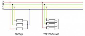
Star and triangle
The three-phase stator winding of the electric motor is connected in a star or delta configuration, depending on the network supply voltage. The ends of a three-phase winding can be: connected inside the electric motor (three wires come out of the motor), brought out (six wires come out), brought into a distribution box (six wires come out of the box, three wires come out of the box).
Phase voltage
- potential difference between the beginning and end of one phase. Another definition for a star connection is that the phase voltage is the potential difference between the line wire and the neutral (note that the delta connection does not have a neutral).
Line voltage
- potential difference between two linear wires (between phases).
| Star | Triangle | Designation |
| Uл, Uф - linear and phase voltage, V, | ||
| Il, Iph - linear and phase current, A, | ||
| S — total power, W | ||
| P—active power, W |
Attention: Although the power for star and delta connections is calculated using the same formula, connecting the same motor in different ways to the same electrical network will result in different power consumption. In this case, incorrect connection of the electric motor can lead to melting of the stator windings.
Example: Let’s say the electric motor was connected in a star configuration to a three-phase alternating current network Ul=380 V (respectively Uph=220 V) and consumed current Il=1 A. Total power consumption: S = 1.73∙380∙1 = 658 Tue
Now let’s change the connection diagram to a “triangle”, the linear voltage will remain the same Uл=380 V, and the phase voltage will increase by the root of 3 times Uф=Uл=380 V. An increase in the phase voltage will lead to an increase in the phase current by the root of 3 times. Thus, the linear current of the delta circuit will be three times greater than the linear current of the star circuit. And therefore the power consumption will be 3 times greater:
S = 1.73∙380∙3 = 1975 W.
Thus, if the motor is designed to be connected to a three-phase AC network in a star configuration, connecting this electric motor in a delta configuration may lead to its failure.
If in normal mode the electric motor is connected in a delta circuit, then to reduce the starting currents during the start-up it can be connected in a star circuit. In this case, along with the starting current, the starting torque will also decrease.
Connecting an electric motor according to a star and delta circuit
Designation of the stator terminals of a three-phase electric motor
Designation of the terminals of the stator windings of newly developed
three-phase machines according to
GOST 26772-85
[2]
| Winding connection diagram, name of phase and output | Pin designation | |
| Start | End | |
| Open circuit (number of pins 6) | ||
| first phase | U1 | U2 |
| second phase | V1 | V2 |
| third phase | W1 | W2 |
| Star connection (number of pins 3 or 4) | ||
| first phase | U | |
| second phase | V | |
| third phase | W | |
| star point (zero point) | N | |
| Delta connection (number of pins 3) | ||
| first conclusion | U | |
| second conclusion | V | |
| third conclusion | W | |
previously developed stator winding terminals
and modernized three-phase machines in accordance with
GOST 26772-85
| Winding connection diagram, name of phase and output | Pin designation | |
| Start | End | |
| Open circuit (number of pins 6) | ||
| first phase | C1 | C4 |
| second phase | C2 | C5 |
| third phase | C3 | C6 |
| Star connection (number of pins 3 or 4) | ||
| first phase | C1 | |
| second phase | C2 | |
| third phase | C3 | |
| zero point | 0 | |
| Delta connection (number of pins 3) | ||
| first conclusion | C1 | |
| second conclusion | C2 | |
| third conclusion | C3 | |
Connecting a three-phase asynchronous motor to a single-phase network using a phase-shifting element
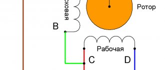
Three-phase asynchronous electric motors can be connected to a single-phase network using phase-shifting elements. In this case, the electric motor will operate either in the mode of a single-phase motor with a starting winding (Figure a, b, d) or in the mode of a capacitor motor with a constantly switched on working capacitor (Figure c, e, f).
Connection diagrams for a three-phase asynchronous electric motor to a single-phase network
The diagrams shown in Figure “a”, “b”, “d” are used when all six ends of the winding are brought out. Electric motors with winding connections according to diagrams “a”, “b”, “d” are almost equivalent to motors that are designed as single-phase electric motors with a starting winding. The rated power is 40-50% of the power in three-phase mode, and when working with a working capacitor it is 75-80%.
The capacity of the working capacitor at a current frequency of 50 Hz for circuits “c”, “d”, “f” is approximately calculated accordingly according to the formulas:
- ,where Crab is the capacitance of the working capacitor, μF,
- Inom – rated (phase) stator current of a three-phase motor, A,
- U1 – single-phase network voltage, V.
Electric motor AIR characteristics
| engine's type | R, kW | Rated rotation speed, rpm | efficiency,* | COS f | 1p/1n | Mn/Mn | Mmax/Mn | 1n, A | Weight, kg |
| AIR56A2 | 0,18 | 2840 | 68,0 | 0,78 | 5,0 | 2,2 | 2,2 | 0,52 | 3,4 |
| AIR56V2 | 0,25 | 2840 | 68,0 | 0,698 | 5,0 | 2,2 | 2,2 | 0,52 | 3,9 |
| AIR56A4 | 0,12 | 1390 | 63,0 | 0,66 | 5,0 | 2,1 | 2,2 | 0,44 | 3,4 |
| AIR56V4 | 0,18 | 1390 | 64,0 | 0,68 | 5,0 | 2,1 | 2,2 | 0,65 | 3,9 |
| AIR63A2 | 0,37 | 2840 | 72,0 | 0,86 | 5,0 | 2,2 | 2,2 | 0,91 | 4,7 |
| AIR63V2 | 0,55 | 2840 | 75,0 | 0,85 | 5,0 | 2,2 | 2,3 | 1,31 | 5,5 |
| AIR63A4 | 0,25 | 1390 | 68,0 | 0,67 | 5,0 | 2,1 | 2,2 | 0,83 | 4,7 |
| AIR63V4 | 0,37 | 1390 | 68,0 | 0,7 | 5,0 | 2,1 | 2,2 | 1,18 | 5,6 |
| AIR63A6 | 0,18 | 880 | 56,0 | 0,62 | 4,0 | 1,9 | 2 | 0,79 | 4,6 |
| AIR63V6 | 0,25 | 880 | 59,0 | 0,62 | 4,0 | 1,9 | 2 | 1,04 | 5,4 |
| AIR71A2 | 0,75 | 2840 | 75,0 | 0,83 | 6,1 | 2,2 | 2,3 | 1,77 | 8,7 |
| AIR71V2 | 1,1 | 2840 | 76,2 | 0,84 | 6,9 | 2,2 | 2,3 | 2,6 | 10,5 |
| AIR71A4 | 0,55 | 1390 | 71,0 | 0,75 | 5,2 | 2,4 | 2,3 | 1,57 | 8,4 |
| AIR71V4 | 0,75 | 1390 | 73,0 | 0,76 | 6,0 | 2,3 | 2,3 | 2,05 | 10 |
| AIR71A6 | 0,37 | 880 | 62,0 | 0,70 | 4,7 | 1,9 | 2,0 | 1,3 | 8,4 |
| AIR71V6 | 0,55 | 880 | 65,0 | 0,72 | 4,7 | 1,9 | 2,1 | 1,8 | 10 |
| AIR71A8 | 0,25 | 645 | 54,0 | 0,61 | 4,7 | 1,8 | 1,9 | 1,1 | 9 |
| AIR71V8 | 0,25 | 645 | 54,0 | 0,61 | 4,7 | 1,8 | 1,9 | 1,1 | 9 |
| AIR80A2 | 1,5 | 2850 | 78,5 | 0,84 | 7,0 | 2,2 | 2,3 | 3,46 | 13 |
| AIR80A2ZHU2 | 1,5 | 2850 | 78,5 | 0,84 | 7,0 | 2,2 | 2,3 | 3,46 | 13 |
| AIR80V2 | 2,2 | 2855 | 81,0 | 0,85 | 7,0 | 2,2 | 2,3 | 4,85 | 15 |
| AIR80V2ZHU2 | 2,2 | 2855 | 81,0 | 0,85 | 7,0 | 2,2 | 2,3 | 4,85 | 15 |
| AIR80A4 | 1,1 | 1390 | 76,2 | 0,77 | 6,0 | 2,3 | 2,3 | 2,85 | 14 |
| AIR80V4 | 1,5 | 1400 | 78,5 | 0,78 | 6,0 | 2,3 | 2,3 | 3,72 | 16 |
| AIR80A6 | 0,75 | 905 | 69,0 | 0,72 | 5,3 | 2,0 | 2,1 | 2,3 | 14 |
| AIR80V6 | 1,1 | 905 | 72,0 | 0,73 | 5,5 | 2,0 | 2,1 | 3,2 | 16 |
| AIR80A8 | 0,37 | 675 | 62,0 | 0,61 | 4,0 | 1,8 | 1,9 | 1,49 | 15 |
| AIR80V8 | 0,55 | 680 | 63,0 | 0,61 | 4,0 | 1,8 | 2,0 | 2,17 | 18 |
| AIR90L2 | 3,0 | 2860 | 82,6 | 0,87 | 7,5 | 2,2 | 2,3 | 6,34 | 17 |
| AIR90L2ZHU2 | 3,0 | 2860 | 82,6 | 0,87 | 7,5 | 2,2 | 2,3 | 6,34 | 17 |
| AIR90L4 | 2,2 | 1410 | 80,0 | 0,81 | 7,0 | 2,3 | 2,3 | 5,1 | 17 |
| AIR90L6 | 1,5 | 920 | 76,0 | 0,75 | 5,5 | 2,0 | 2,1 | 4,0 | 18 |
| AIR90LA8 | 0,75 | 680 | 70,0 | 0,67 | 4,0 | 1,8 | 2,0 | 2,43 | 23 |
| AIR90LB8 | 1,1 | 680 | 72,0 | 0,69 | 5,0 | 1,8 | 2,0 | 3,36 | 28 |
| AIR100S2 | 4,0 | 2880 | 84,2 | 0,88 | 7,5 | 2,2 | 2,3 | 8,2 | 20,5 |
| AIR100S2ZHU2 | 4,0 | 2880 | 84,2 | 0,88 | 7,5 | 2,2 | 2,3 | 8,2 | 20,5 |
| AIR100L2 | 5,5 | 2900 | 85,7 | 0,88 | 7,5 | 2,2 | 2,3 | 11,1 | 28 |
| AIR100L2ZHU2 | 5,5 | 2900 | 85,7 | 0,88 | 7,5 | 2,2 | 2,3 | 11,1 | 28 |
| AIR100S4 | 3,0 | 1410 | 82,6 | 0,82 | 7,0 | 2,3 | 2,3 | 6,8 | 21 |
| AIR100L4 | 4,0 | 1435 | 84,2 | 0,82 | 7,0 | 2,3 | 2,3 | 8,8 | 37 |
| AIR100L6 | 2,2 | 935 | 79,0 | 0,76 | 6,5 | 2,0 | 2,1 | 5,6 | 33,5 |
| AIR100L8 | 1,5 | 690 | 74,0 | 0,70 | 5,0 | 1,8 | 2,0 | 4,4 | 33,5 |
| AIR112M2 | 7,5 | 2895 | 87,0 | 0,88 | 7,5 | 2,2 | 2,3 | 14,9 | 49 |
| AIR112M2ZHU2 | 7,5 | 2895 | 87,0 | 0,88 | 7,5 | 2,2 | 2,3 | 14,9 | 49 |
| AIR112M4 | 5,5 | 1440 | 85,7 | 0,83 | 7,0 | 2,3 | 2,3 | 11,7 | 45 |
| AIR112MA6 | 3,0 | 960 | 81,0 | 0,73 | 6,5 | 2,1 | 2,1 | 7,4 | 41 |
| AIR112MB6 | 4,0 | 860 | 82,0 | 0,76 | 6,5 | 2,1 | 2,1 | 9,75 | 50 |
| AIR112MA8 | 2,2 | 710 | 79,0 | 0,71 | 6,0 | 1,8 | 2,0 | 6,0 | 46 |
| AIR112MB8 | 3,0 | 710 | 80,0 | 0,73 | 6,0 | 1,8 | 2,0 | 7,8 | 53 |
| AIR132M2 | 11 | 2900 | 88,4 | 0,89 | 7,5 | 2,2 | 2,3 | 21,2 | 54 |
| AIR132M2ZHU2 | 11 | 2900 | 88,4 | 0,89 | 7,5 | 2,2 | 2,3 | 21,2 | 54 |
| AIR132S4 | 7,5 | 1460 | 87,0 | 0,84 | 7,0 | 2,3 | 2,3 | 15,6 | 52 |
| AIR132M4 | 11 | 1450 | 88,4 | 0,84 | 7,0 | 2,2 | 2,3 | 22,5 | 60 |
| AIR132S6 | 5,5 | 960 | 84,0 | 0,77 | 6,5 | 2,1 | 2,1 | 12,9 | 56 |
| AIR132M6 | 7,5 | 970 | 86,0 | 0,77 | 6,5 | 2,0 | 2,1 | 17,2 | 61 |
| AIR132S8 | 4,0 | 720 | 81,0 | 0,73 | 6,0 | 1,9 | 2,0 | 10,3 | 70 |
| AIR132M8 | 5,5 | 720 | 83,0 | 0,74 | 6,0 | 1,9 | 2,0 | 13,6 | 86 |
| AIR160S2 | 15 | 2930 | 89,4 | 0,89 | 7,5 | 2,2 | 2,3 | 28,6 | 116 |
| AIR160S2ZHU2 | 15 | 2930 | 89,4 | 0,89 | 7,5 | 2,2 | 2,3 | 28,6 | 116 |
| AIR160M2 | 18,5 | 2930 | 90,0 | 0,90 | 7,5 | 2,0 | 2,3 | 34,7 | 130 |
| AIR160M2ZHU2 | 18,5 | 2930 | 90,0 | 0,90 | 7,5 | 2,0 | 2,3 | 34,7 | 130 |
| AIR160S4 | 15 | 1460 | 89,4 | 0,85 | 7,5 | 2,2 | 2,3 | 30,0 | 125 |
| AIR160S4ZHU2 | 15 | 1460 | 89,4 | 0,85 | 7,5 | 2,2 | 2,3 | 30,0 | 125 |
| AIR160M4 | 18,5 | 1470 | 90,0 | 0,86 | 7,5 | 2,2 | 2,3 | 36,3 | 142 |
| AIR160S6 | 11 | 970 | 87,5 | 0,78 | 6,5 | 2,0 | 2,1 | 24,5 | 125 |
| AIR160M6 | 15 | 970 | 89,0 | 0,81 | 7,0 | 2,0 | 2,1 | 31,6 | 155 |
| AIR160S8 | 7,5 | 720 | 85,5 | 0,75 | 6,0 | 1,9 | 2,0 | 17,8 | 125 |
| AIR160M8 | 11 | 730 | 87,5 | 0,75 | 6,5 | 2,0 | 2,0 | 25,5 | 150 |
| AIR180S2 | 22 | 2940 | 90,5 | 0,90 | 7,5 | 2,0 | 2,3 | 41,0 | 150 |
| AIR180S2ZHU2 | 22 | 2940 | 90,5 | 0,90 | 7,5 | 2,0 | 2,3 | 41,0 | 150 |
| AIR180M2 | 30 | 2950 | 91,4 | 0,90 | 7,5 | 2,0 | 2,3 | 55,4 | 170 |
| AIR180M2ZHU2 | 30 | 2950 | 91,4 | 0,90 | 7,5 | 2,0 | 2,3 | 55,4 | 170 |
| AIR180S4 | 22 | 1470 | 90,5 | 0,86 | 7,5 | 2,2 | 2,3 | 43,2 | 160 |
| AIR180S4ZHU2 | 22 | 1470 | 90,5 | 0,86 | 7,5 | 2,2 | 2,3 | 43,2 | 160 |
| AIR180M4 | 30 | 1470 | 91,4 | 0,86 | 7,2 | 2,2 | 2,3 | 57,6 | 190 |
| AIR180M4ZHU2 | 30 | 1470 | 91,4 | 0,86 | 7,2 | 2,2 | 2,3 | 57,6 | 190 |
| AIR180M6 | 18,5 | 980 | 90,0 | 0,81 | 7,0 | 2,1 | 2,1 | 38,6 | 160 |
| AIR180M8 | 15 | 730 | 88,0 | 0,76 | 6,6 | 2,0 | 2,0 | 34,1 | 172 |
| AIR200M2 | 37 | 2950 | 92,0 | 0,88 | 7,5 | 2,0 | 2,3 | 67,9 | 230 |
| AIR200M2ZHU2 | 37 | 2950 | 92,0 | 0,88 | 7,5 | 2,0 | 2,3 | 67,9 | 230 |
| AIR200L2 | 45 | 2960 | 92,5 | 0,90 | 7,5 | 2,0 | 2,3 | 82,1 | 255 |
| AIR200L2ZHU2 | 45 | 2960 | 92,5 | 0,90 | 7,5 | 2,0 | 2,3 | 82,1 | 255 |
| AIR200M4 | 37 | 1475 | 92,0 | 0,87 | 7,2 | 2,2 | 2,3 | 70,2 | 230 |
| AIR200L4 | 45 | 1475 | 92,5 | 0,87 | 7,2 | 2,2 | 2,3 | 84,9 | 260 |
| AIR200M6 | 22 | 980 | 90,0 | 0,83 | 7,0 | 2,0 | 2,1 | 44,7 | 195 |
| AIR200L6 | 30 | 980 | 91,5 | 0,84 | 7,0 | 2,0 | 2,1 | 59,3 | 225 |
| AIR200M8 | 18,5 | 730 | 90,0 | 0,76 | 6,6 | 1,9 | 2,0 | 41,1 | 210 |
| AIR200L8 | 22 | 730 | 90,5 | 0,78 | 6,6 | 1,9 | 2,0 | 48,9 | 225 |
| AIR225M2 | 55 | 2970 | 93,0 | 0,90 | 7,5 | 2,0 | 2,3 | 100 | 320 |
| AIR225M4 | 55 | 1480 | 93,0 | 0,87 | 7,2 | 2,2 | 2,3 | 103 | 325 |
| AIR225M6 | 37 | 980 | 92,0 | 0,86 | 7,0 | 2,1 | 2,1 | 71,0 | 360 |
| AIR225M8 | 30 | 735 | 91,0 | 0,79 | 6,5 | 1,9 | 2,0 | 63 | 360 |
| AIR250S2 | 75 | 2975 | 93,6 | 0,90 | 7,0 | 2,0 | 2,3 | 135 | 450 |
| AIR250M2 | 90 | 2975 | 93,9 | 0,91 | 7,1 | 2,0 | 2,3 | 160 | 530 |
| AIR250S4 | 75 | 1480 | 93,6 | 0,88 | 6,8 | 2,2 | 2,3 | 138,3 | 450 |
| AIR250M4 | 90 | 1480 | 93,9 | 0,88 | 6,8 | 2,2 | 2,3 | 165,5 | 495 |
| AIR250S6 | 45 | 980 | 92,5 | 0,86 | 7,0 | 2,1 | 2,0 | 86,0 | 465 |
| AIR250M6 | 55 | 980 | 92,8 | 0,86 | 7,0 | 2,1 | 2,0 | 104 | 520 |
| AIR250S8 | 37 | 740 | 91,5 | 0,79 | 6,6 | 1,9 | 2,0 | 78 | 465 |
| AIR250M8 | 45 | 740 | 92,0 | 0,79 | 6,6 | 1,9 | 2,0 | 94 | 520 |
| AIR280S2 | 110 | 2975 | 94,0 | 0,91 | 7,1 | 1,8 | 2,2 | 195 | 650 |
| AIR280M2 | 132 | 2975 | 94,5 | 0,91 | 7,1 | 1,8 | 2,2 | 233 | 700 |
| AIR280S4 | 110 | 1480 | 94,5 | 0,88 | 6,9 | 2,1 | 2,2 | 201 | 650 |
| AIR280M4 | 132 | 1480 | 94,8 | 0,88 | 6,9 | 2,1 | 2,2 | 240 | 700 |
| AIR280S6 | 75 | 985 | 93,5 | 0,86 | 6,7 | 2,0 | 2,0 | 142 | 690 |
| AIR280M6 | 90 | 985 | 93,8 | 0,86 | 6,7 | 2,0 | 2,0 | 169 | 800 |
| AIR280S8 | 55 | 740 | 92,8 | 0,81 | 6,6 | 1,8 | 2,0 | 111 | 690 |
| AIR280M8 | 75 | 740 | 93,5 | 0,81 | 6,2 | 1,8 | 2,0 | 150 | 800 |
| AIR315S2 | 160 | 2975 | 94,6 | 0,92 | 7,1 | 1,8 | 2,2 | 279 | 1170 |
| AIR315M2 | 200 | 2975 | 94,8 | 0,92 | 7,1 | 1,8 | 2,2 | 248 | 1460 |
| AIR315MV2 | 250 | 2975 | 94,8 | 0,92 | 7,1 | 1,8 | 2,2 | 248 | 1460 |
| AIR315S4 | 160 | 1480 | 94,9 | 0,89 | 6,9 | 2,1 | 2,2 | 288 | 1000 |
| AIR315M4 | 200 | 1480 | 94,9 | 0,89 | 6,9 | 2,1 | 2,2 | 360 | 1200 |
| AIR315S6 | 110 | 985 | 94,0 | 0,86 | 6,7 | 2,0 | 2,0 | 207 | 880 |
| AIR315M(A)6 | 132 | 985 | 94,2 | 0,87 | 6,7 | 2,0 | 2,0 | 245 | 1050 |
| AIR315MV6 | 160 | 985 | 94,2 | 0,87 | 6,7 | 2,0 | 2,0 | 300 | 1200 |
| AIR315S8 | 90 | 740 | 93,8 | 0,82 | 6,4 | 1,8 | 2,0 | 178 | 880 |
| AIR315M(A)8 | 110 | 740 | 94,0 | 0,82 | 6,4 | 1,8 | 2,0 | 217 | 1050 |
| AIR315MV8 | 132 | 740 | 94,0 | 0,82 | 6,4 | 1,8 | 2,0 | 260 | 1200 |
| AIR355S2 | 250 | 2980 | 95,5 | 0,92 | 6,5 | 1.6 | 2,3 | 432,3 | 1700 |
| AIR355M2 | 315 | 2980 | 95,6 | 0,92 | 7,1 | 1,6 | 2,2 | 544 | 1790 |
| AIR355S4 | 250 | 1490 | 95,6 | 0,90 | 6,2 | 1,9 | 2,9 | 441 | 1700 |
| AIR355M4 | 315 | 1480 | 95,6 | 0,90 | 6,9 | 2,1 | 2,2 | 556 | 1860 |
| AIR355MA6 | 200 | 990 | 94,5 | 0,88 | 6,7 | 1,9 | 2,0 | 292 | 1550 |
| AIR355S6 | 160 | 990 | 95,1 | 0,88 | 6,3 | 1,6 | 2,8 | 291 | 1550 |
| AIR355MV6 | 250 | 990 | 94,9 | 0,88 | 6,7 | 1,9 | 2,0 | 454,8 | 1934 |
| AIR355L6 | 315 | 990 | 94,5 | 0,88 | 6,7 | 1,9 | 2,0 | 457 | 1700 |
| AIR355S8 | 132 | 740 | 94,3 | 0,82 | 6,4 | 1,9 | 2,7 | 259,4 | 1800 |
| AIR355MA8 | 160 | 740 | 93,7 | 0,82 | 6,4 | 1,8 | 2,0 | 261 | 2000 |
| AIR355MV8 | 200 | 740 | 94,2 | 0,82 | 6,4 | 1,8 | 2,0 | 315 | 2150 |
| AIR355L8 | 132 | 740 | 94,5 | 0,82 | 6,4 | 1,8 | 2,0 | 387 | 2250 |
X
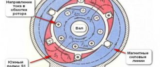
Three-phase asynchronous motor with wound rotor
Asynchronous motor with wound rotor
— an asynchronous motor in which the rotor winding is connected to slip rings [1].
Before the widespread use of frequency converters, medium and high power asynchronous motors were made with a wound rotor. Three-phase slip-rotor induction motors (ASMs) are typically used in applications with severe starting conditions, such as AC crane motors, or to drive devices requiring continuously variable speed control.
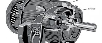
ADFR design
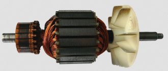
Slip rotor
Structurally, the phase rotor is a three-phase winding (similar to the stator winding) placed in the slots of the phase rotor core. The ends of the phases of such a rotor winding are usually connected in a “star”, and the beginnings are connected to slip rings isolated from each other and from the shaft. A three-phase starting or control rheostat is usually connected to the slip rings through brushes. Asynchronous motors with a wound rotor have a more complex design than motors with a squirrel-cage rotor, but have better starting and control properties.
Slip rotor