Today, interest in LEDs has increased significantly, because they are the future in lighting. The question arises of how an LED is connected to a 220 V network, which we will answer in detail in this article. We will also consider the supply voltage, pinout, pinout, connection diagrams and various calculations.
An LED is a semiconductor device where electric current turns into light. A diode allows current to flow in only one direction. LEDs are connected to 220V thanks to a driver that meets all the characteristics.
The connection according to the scheme can be parallel or serial. The LED is characterized by a durable housing, long and reliable operation.
LED pinout
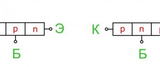
Before we consider how to properly connect an LED, you need to learn how to determine its polarity. Most often, indicator LEDs have two terminals: anode and cathode. Much less often, in a case with a diameter of 5 mm, there are specimens that have 3 or 4 terminals for connection. But it’s also not difficult to figure out their pinouts.
In total, there are 3 reliable ways to determine polarity: visually, using a multimeter and by connecting to a voltage source. Each of them is unique and interesting in its own way, and therefore this topic is included in a separate article: “Where is the plus and where is the minus?”
SMD LEDs can have 4 outputs (2 anodes and 2 cathodes), which is due to their production technology. The third and fourth pins can be electrically unused, but used as an additional heat sink.
The pinout shown is not standard. To calculate the polarity, it is better to first look at the datasheet and then confirm what you see with a multimeter. You can visually determine the polarity of an SMD LED with two terminals by looking at the cut. The cut (key) in one of the corners of the housing is always located closer to the cathode (minus).
Determine polarity with a multimeter
When replacing diodes with new ones, you can determine the plus and minus of your device's power supply from the board.
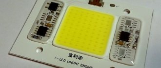
LEDs in spotlights and lamps are usually soldered onto an aluminum plate, on top of which a dielectric and current-carrying tracks are applied. It usually has a white coating on top; it often contains information about the characteristics of the power source, and sometimes the pinout.
But how can you find out the polarity of an LED in a light bulb or matrix if there is no information on the board?
For example, on this board the poles of each LED are indicated and their name is 5630.
To check for serviceability and determine the plus and minus of the LED, use a multimeter. We connect the black probe to minus, com or a socket with a grounding sign. The designation may differ depending on the multimeter model.
Next, select the Ohmmeter mode or the diode test mode. Then we connect the multimeter probes one by one to the diode terminals, first in one order, and then vice versa. When at least some values appear on the screen, or the diode lights up, it means the polarity is correct. In diode testing mode, the values are 500-1200 mV.
In measurement mode, the values will be similar to those in the figure. A unit in the leftmost digit indicates exceeding the limit, or infinity.
The simplest LED connection diagram
There is nothing easier than connecting an LED to a low-voltage DC source. This could be a battery, accumulator or low-power power supply. It is better if the voltage is at least 5 V and no more than 24 V. Such a connection will be safe, and to implement it you will only need 1 additional element - a low-power resistor. Its task is to limit the current flowing through the pn junction at a level not higher than the nominal value. To do this, the resistor is always installed in series with the emitting diode.
Always maintain correct polarity when connecting an LED to a constant voltage (current) source.
If a resistor is excluded from the circuit, then the current in the circuit will be limited only by the internal resistance of the EMF source, which is very small. The result of such a connection will be instant failure of the emitting crystal.
Connection options
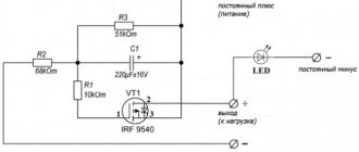
To make a serial connection of 220V LEDs, use the diagram below.
In this case, capacitor C1 limits the current to a greater extent; it plays the role of reactance. We wrote more about calculating a capacitor in the article . To obtain the required capacitance value of the capacitor, use the online calculator:
This way you can connect even one LED.
If you want to build a 100 volt DC LED series circuit, you need to include about 30 LEDs in the circuit. Then the required voltage will be about 90 volts. Calculate the resistor using the formula in the previous sections of the article.
A capacitor is needed to smooth out current ripples, a resistor in parallel is needed to discharge the capacitor after turning off the device, for safety reasons. If the power source is sufficiently stabilized, they can be excluded.
Calculation of the limiting resistor
Looking at the current-voltage characteristic of the LED, it becomes clear how important it is not to make a mistake when calculating the limiting resistor.
Even a slight increase in the rated current will lead to overheating of the crystal and, as a result, to a decrease in operating life. The choice of resistor is made according to two parameters: resistance and power. Resistance is calculated using the formula:
- U – supply voltage, V;
- ULED – forward voltage drop across the LED (nameplate value), V;
- I – rated current (certificate value), A.
The result obtained should be rounded up to the nearest value from the E24 series, and then calculate the power that the resistor will have to dissipate:
R – resistance of the resistor accepted for installation, Ohm.
More detailed information about calculations with practical examples can be found in the article on calculating a resistor for an LED. And those who do not want to dive into the nuances can quickly calculate the resistor parameters using an online calculator.
Turning on the LEDs from the power supply
We will talk about power supplies (PSUs) operating from a 220 V AC network. But even they can differ greatly in output parameters. It can be:
- AC voltage sources, inside of which there is only a step-down transformer;
- unstabilized direct voltage sources (DCS);
- stabilized PPI;
- stabilized direct current sources (LED drivers).
You can connect an LED to any of them by adding the necessary radio elements to the circuit. Most often, stabilized power supply voltages of 5 V or 12 V are used as a power supply. This type of power supply means that in the event of possible fluctuations in the network voltage, as well as when the load current changes within a given range, the output voltage will not change. This advantage allows you to connect LEDs to the power supply using only resistors. And it is precisely this connection principle that is implemented in circuits with indicator LEDs.
Powerful LEDs and LED matrices must be connected through a current stabilizer (driver). Despite their higher cost, this is the only way to guarantee stable brightness and long-term operation, as well as to eliminate premature replacement of an expensive light-emitting element. This connection does not require an additional resistor, and the LED is connected directly to the driver output subject to the following conditions:
- Idriver – driver current according to the passport, A;
- ILED – rated current of the LED, A.
If the condition is not met, the connected LED will burn out due to overcurrent.
You can even use one 1.5 V AA battery as a power source. But to do this, you will have to assemble a small electrical circuit that will increase the supply voltage to the required level. You can learn how to do this in the article “How to connect an LED from a 1.5 V battery.”
What about pulsations?
In both schemes, the LED will light only during the positive half-cycle of the mains voltage. That is, it will flicker at a frequency of 50 Hz or 50 times per second, and the pulsation range will be equal to 100% (10 ms on, 10 ms off, and so on). It will be noticeable to the eye.
In addition, when flickering LEDs illuminate any moving objects, for example, fan blades, bicycle wheels, etc., a stroboscopic effect will inevitably occur. In some cases, this effect may be unacceptable or even dangerous. For example, when working at a machine, it may seem that the cutter is motionless, but in fact it is rotating at breakneck speed and is just waiting for you to stick your fingers into it.
To make the ripple less noticeable, you can double the LED switching frequency using a full-wave rectifier (diode bridge):
Please note that compared to circuit #2 with the same resistor value, we got twice the average current. And, accordingly, four times the power dissipation of the resistors.
There are no special requirements for the diode bridge, the main thing is that the diodes that make it up can withstand half the operating current of the LED. The reverse voltage on each of the diodes will be completely negligible.
Another option is to organize back-to-back switching of two LEDs. Then one of them will burn during the positive half-wave, and the second during the negative half-wave.
The trick is that with this connection, the maximum reverse voltage on each of the LEDs will be equal to the forward voltage of the other LED (several volts maximum), so each of the LEDs will be reliably protected from breakdown.
LEDs should be placed as close to each other as possible. Ideally, try to find a dual LED, where both crystals are placed in the same housing and each has its own terminals (although I have never seen such ones).
Generally speaking, for LEDs that perform an indicator function, the amount of ripple is not very important. For them, the most important thing is the most noticeable difference between the on and off states (on/off indication, playback/recording, charge/discharge, normal/emergency, etc.)
But when creating lamps, you should always try to reduce pulsations to a minimum. And not so much because of the dangers of the stroboscopic effect, but because of their harmful effects on the body.
What pulsations are considered acceptable?
It all depends on the frequency: the lower it is, the more noticeable the pulsations. At frequencies above 300 Hz, ripples become completely invisible and are not normalized at all, that is, even 100% are considered normal.
Despite the fact that light pulsations at frequencies of 60-80 Hz and higher are not visually perceived, nevertheless, they can cause increased eye fatigue, general fatigue, anxiety, decreased visual performance and even headaches.
To prevent the above consequences, the international standard IEEE 1789-2015 recommends a maximum brightness ripple level for a frequency of 100 Hz of 8% (guaranteed safe level of 3%). For a frequency of 50 Hz, this will be 1.25% and 0.5%, respectively. But this is for perfectionists.
In fact, in order for LED brightness pulsations to stop being at least somewhat annoying, it is enough that they do not exceed 15-20%. This is exactly the level of flickering of medium-power incandescent lamps, and yet no one has ever complained about them. And our Russian SNiP 23-05-95 allows light flickering of 20% (and only for particularly painstaking and responsible work the requirement is increased to 10%).
In accordance with GOST 33393-2015 “Buildings and structures. Methods for measuring the pulsation coefficient of illumination” to assess the magnitude of pulsations, a special indicator is introduced - the pulsation coefficient (Kp).
Coeff. pulsations are generally calculated using a complex formula using an integral function, but for harmonic oscillations the formula is simplified to the following:
Kp = (Emax - Emin) / (Emax + Emin) ⋅ 100%,
where Emax is the maximum illumination value (amplitude), and Emin is the minimum.
We will use this formula to calculate the capacitance of the smoothing capacitor.
You can very accurately determine the ripples of any light source using a solar panel and an oscilloscope:
How to reduce ripple?
Let's see how to connect an LED to a 220 volt network to reduce ripple. To do this, the easiest way is to solder a storage (smoothing) capacitor in parallel with the LED:
Due to the nonlinear resistance of LEDs, calculating the capacitance of this capacitor is a rather non-trivial task.
However, this task can be simplified by making a few assumptions. First, imagine the LED as an equivalent fixed resistor:
And secondly, pretend that the brightness of the LED (and, consequently, the illumination) has a linear dependence on the current.
Let's try to approximately calculate the capacitance of a capacitor using a specific example.
Calculation of the capacitance of the smoothing capacitor
Let's say we want to get the coefficient. ripple 2.5% at a current through the LED of 20 mA. And let us have at our disposal an LED on which, at a current of 20 mA, 2 V drops. The network frequency, as usual, is 50 Hz.
Since we decided that the brightness linearly depends on the current through the LED, and we represented the LED itself as a simple resistor, we can easily replace the illumination in the formula for calculating the ripple coefficient with the voltage on the capacitor:
Kp = (Umax - Umin) / (Umax + Umin) ⋅ 100%
We substitute the original data and calculate Umin:
2.5% = (2V - Umin) / (2V + Umin) ⋅ 100% => Umin = 1.9V
The period of voltage fluctuations in the network is 0.02 s (1/50).
Thus, the voltage oscillogram on the capacitor (and therefore on our simplified LED) will look something like this:
Let's remember trigonometry and calculate the charging time of the capacitor (for simplicity, we will not take into account the resistance of the ballast resistor):
tzare = arccos(Umin/Umax) / 2πf = arccos(1.9/2) / (2 ⋅ 3.1415 ⋅ 50) = 0.0010108 s
The rest of the period the Conder will be discharged. Moreover, the period in this case needs to be halved, because We use a full-wave rectifier:
tdisr = T - tsar = 0.02/2 - 0.0010108 = 0.008989 s
It remains to calculate the capacity:
C = ILED ⋅ dt/dU = 0.02 ⋅ 0.008989/(2-1.9) = 0.0018 F (or 1800 µF)
In practice, it is unlikely that anyone will install such a large condenser for the sake of one small LED. Although, if the goal is to obtain a ripple of 10%, then only 440 uF is needed.
Serial connection
Assembling a working circuit using one LED is not difficult. It's another matter when there are several of them. How to correctly connect 2, 3... N LEDs? To do this, you need to learn how to calculate more complex switching circuits. The series connection circuit is a chain of several LEDs, in which the cathode of the first LED is connected to the anode of the second, the cathode of the second to the anode of the third, and so on.
A current of the same magnitude flows through all elements of the circuit:
And the voltage drops are summed up:
Based on this, we can draw conclusions:
- It is advisable to combine only LEDs with the same operating current into a series circuit;
- if one LED fails, the circuit will open;
- The number of LEDs is limited by the power supply voltage.
Video
Connection errors can lead to unpleasant consequences, from simple breakdown of LEDs to self-harm. Therefore, we strongly recommend watching a video where common errors are discussed.
Conclusion
After reading the article, we can conclude that all LEDs, regardless of the operating voltage, are always connected in parallel or in series - a school physics course. It is also worth remembering that no LED is connected directly to a 220V network; you should always use protective elements in the connection diagram. The type of protective elements used depends on the type of light-emitting diode being connected.
Parallel connection
If you need to light several LEDs from a power supply with a voltage of, for example, 5 V, then they will have to be connected in parallel. In this case, a resistor must be placed in series with each LED.
Formulas for calculating currents and voltages will take the following form:
Thus, the sum of the currents in each branch should not exceed the maximum permissible current of the power supply unit. When connecting LEDs of the same type in parallel, it is enough to calculate the parameters of one resistor, and the rest will be of the same value.
All the rules for serial and parallel connection, visual examples, as well as information on how not to turn on LEDs can be found in this article.
Connection to AC mains
Connecting LEDs from a power supply is not always advisable. Especially when it comes to the need to backlight a switch or indicate the presence of voltage in the power strip. For such purposes, it will be enough to assemble one of the simple circuits for connecting an LED to a 220 V network. For example, a circuit with a current-limiting resistor and a rectifying diode that protects the LED from reverse voltage.
The resistance and power of the resistor are calculated using a simplified formula, neglecting the voltage drop across the LED and diode, since it is 2 orders of magnitude less than the mains voltage:
Due to the high power dissipation (2–5 W), the resistor is often replaced with a non-polar capacitor. Working on alternating current, it seems to “extinguish” excess voltage and hardly heats up.
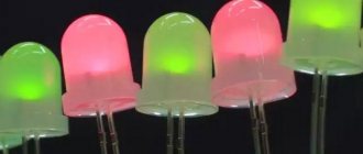
Connecting flashing and multi-color LEDs
Externally, flashing LEDs are no different from conventional analogues and can flash in one, two or three colors according to the algorithm specified by the manufacturer. The internal difference is the presence of another substrate under the housing, on which the integrated pulse generator is located. The rated operating current, as a rule, does not exceed 20 mA, and the voltage drop can vary from 3 to 14 V. Therefore, before connecting a flashing LED, you need to familiarize yourself with its characteristics. If they are not there, then you can find out the parameters experimentally by connecting to an adjustable power supply at 5–15 V through a resistor with a resistance of 51–100 Ohms.
The multicolor RGB LED housing contains 3 independent crystals of green, red and blue. Therefore, when calculating resistor values, you need to remember that each glow color has its own voltage drop.
By appearance
Sometimes you can tell the polarity by appearance. Some types of LEDs have a key on the housing - a protrusion or mark. To determine which pin is marked with a key, it is better to consult the reference materials.
The key is at the cathode of the AL102 light-emitting diode.
Appearance of the pin layout of the AL307 LED.
For packageless LEDs produced in the USSR, you can find out the pinout by looking closely at the internal structure of the device through the layer of compound. The cathode terminal has a large area and is made in the form of a flag . This principle could become a standard, but now manufacturers do not strictly adhere to it, so this method is unreliable, especially for elements from an unknown manufacturer. Therefore, this definition of conclusions can be used only for preliminary guidance.
The pinout of domestic LEDs can be recognized by the length of the legs - the anode lead is made shorter. But this is true only for elements that have not been used - when being installed in place, the leads can be cut off arbitrarily.
For clarity, we recommend watching the video.
Once again about three important points
- Direct rated current is the main parameter of any LED. By lowering it, we lose brightness, and by overestimating it, we sharply reduce the service life. Therefore, the best power source is an LED driver; when connected to it, a constant current of the required value will always flow through the LED.
- The voltage given in the datasheet for the LED is not decisive and only indicates how many volts will drop across the pn junction when the rated current flows. Its value must be known in order to correctly calculate the resistor resistance if the LED will be powered by a conventional power supply.
- To connect high-power LEDs, it is important not only to have a reliable power supply, but also to have a high-quality cooling system. Installing LEDs with a power consumption of more than 0.5 W on the radiator will guarantee their stable and long-term operation.
How to determine the anode and cathode of diodes 1W or more
In flashlights and spotlights, 5mm samples are used less and less; they have been replaced by powerful elements with a power of 1 watt or more or SMD. To understand where the plus and minus are on a powerful LED, you need to carefully look at the element from all sides.
The most common models in such a case have a power of 0.5 watts. The polarity mark is circled in red in the figure. In this case, the anode of the 1W LED is marked with a plus sign.