The name itself—two-color LED—is based on the fact that the chip is capable of glowing in two colors. A striking example of this type of diode is charging a mobile phone, charging batteries, where the indicator glows red during charging, and as the battery is filled with charge, the color changes to green.
[contents]
Bi-color LEDs are divided into several types. The most common are three-terminal LEDs. Two green and red LEDs are integrated into one housing.
—> —> Two-color LED with two leads
Bicolor LEDs have two terminals. The color changes depending on which direction the current flows. The control diagram for two-color LEDs is presented below.
Proper connection of bi-color LED
The diodes are connected in parallel. When current flows in one direction, the second diode turns off and does not light up. In the case of reverse current flow, the glow occurs in reverse. When using a PWM controller, you can light both LEDs at once, and as a result of mixing the colors you will get yellow or several other shades.
Despite the fact that in this diagram we see only two diodes, in some instructions it is usually called three-color. Such diodes have three terminals. This division is conditional, so you should not focus on this.
Scope of application of two-color LEDs
A 2-color LED is an integrated assembly with two light-emitting crystals on one substrate. Despite the rather limited emission spectrum, 2-color LEDs are widely used in:
- instrument making, as a two-color 5mm LED used as an indicator;
- advertising business to attract consumer attention;
- decorating rooms using the play of light;
- modern signaling equipment, such as a two-color LED flasher, traffic lights;
- car tuning;
These devices are widely used in alarm, indication and visual design systems. 2-color LED lighting is actively used in the creation of electronic displays and signs. In addition, a two-color LED is used as a rotation indicator for a DC motor, showing which direction it is rotating.
LED for 2 colors – these are two ordinary LEDs in one housing. It has two legs and each is simultaneously the cathode of an LED of one color and the anode of a different color. Therefore, the color of the lamps will depend on the direction in which the current flows through the two-color diode. This LED requires only one resistor. Two-color LEDs are less popular than three-color LEDs. An example of a 2-color LED is charging for a mobile device and a battery, when the indicator light glows red during charging, and after charging the battery the light changes to green.
In cars, LED lamps are used where 2 colors are required in the headlight, when one lamp simultaneously serves as a marker and a turn signal. The dimensions will be red, and the turn signals will be yellow.
How to connect a two-color LED?
Connecting LEDs to a circuit requires connecting a ballast resistor, which is built into modern LEDs. By limiting the current in the circuit, connecting the LED is possible with a network voltage of 220V.
Main conclusions
The use of RGB LEDs is constantly expanding. They perform various tasks:
- creating dynamic lighting effects;
- decoration of buildings, structures, interiors;
- illumination and accentuation of advertising structures;
- design of public events, concerts, performances.
The area of use of RGB LEDs is increasing and actively developing. New lighting options are emerging. Software packages are being developed for use in microcontrollers. Share your ways of using RGB LEDs in the comments.
Connection diagrams for two-color LEDs
To make an electrical appliance with your own hands, you need to know how to connect a two-light LED. The simplest (but not entirely correct) option is to connect power to the legs through a resistor and determine the on/off cycles.
To add a resistor to the circuit, you need to calculate its resistance and power values.
Since 2015, GOST 29433-2014 has defined new power supply voltage parameters:
- nominal 230 V;
- minimum 207 V, under load 198 V;
- maximum 253 V.
The resistance of the resistor must be of such a value that the current necessary for the normal functioning of the two-color LED can flow through it, but the element does not overheat. Therefore, the rated current value of 20 mA for calculations is replaced by another value - 7 mA = 0.007 A, which allows the diode to glow normally.
Resistance:
You need to buy a 33 kOhm element.
Resistor power:
You need to buy a 2 W element.
To check, the current at maximum voltage is calculated:
Power:
This means that a 2 W resistor will not overheat even at the maximum network voltage.
On timer 555
The 555 timer is an integrated device that generates pulses at certain intervals. Models are available in plastic and metal DIP and SMD housings for 4.5 – 16 V. The main area of application in everyday life is the control of three-color strips and lamps. Timer 555 turns on the colors one by one. The standard supply voltage is 5 V, you can convert it to 12 V by changing the resistance of the resistors.
A similar circuit with a 555 timer can be created to control a two-color LED. It is necessary to power the circuit from a 220 V network through a step-down transformer. The voltage is stabilized by the 7805 regulator. The transformer can have one or more windings. The second option requires an additional output from the 12 V winding.
If the LED is multicolor, the circuit includes as many timers as there are colors. The colored elements are connected to the 555 pins via resistors. As the resistance changes, the glow intensity changes from minimum to maximum value.
Up to 1a
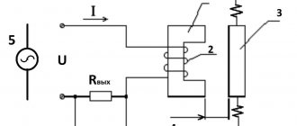
To drive two-color LEDs operating at currents up to 1 A, a TA7291P circuit is used, equipped with two inputs and outputs. A two-color LED is connected to the output. If the logic of the diodes, transistors and relays is the same, but the outputs are different, the chip does not light up.
With the same logic levels, the circuit works differently. If the levels at the inputs are different, one of the outputs is connected to a common wiring, which leads to the cathode of a two-color diode and a resistor being connected to it. The voltage at the second output changes simultaneously with the voltage at the input. This makes it possible to adjust the intensity of the glow.
The voltage at the second output is supplied from the microcontroller that produces pulses. In addition to the brightness of the glow, the microcontroller controls the inputs, so it is possible to regulate the control algorithm and shades of the glow.
LED connection
Figure 2 shows how an LED is typically connected. Here we take an LED with a drop voltage of 1.6V (Un). The battery is 4.5V, so in order not to burn out the LED, resistor R1 is connected in series with it, through which the excess voltage drops (4.5 -1.6 = 2.9V).
Rice. 2. Diagram of connecting an LED through a quenching resistor.
Now let's try to calculate the resistance of resistor R1. Let's say the rated current through the LED is 10mA, the drop voltage is 1.6V, the power supply voltage is 4.5V. That is, the resistance of resistor R1 should be such that it drops 2.9V, and there is a current of 10mA (0.01 A).
Let's move on to Ohm's Law: R= U/I = 2.9 / 0.01 = 290 Ohm. That is, it would be quite normal to set R1 with a resistance of 300 Ohms. There are LEDs of different colors - red, green, yellow, blue, white. Of course, they also differ in the brightness of the light, the voltage drop, and the current.
A little theory
An LED requires a constant voltage or current to operate properly. They should be:
- Constant in direction. That is, the current in the LED circuit when voltage is applied must flow from the “+” of the voltage source to its “–”.
- Stable, i.e. constant in value, during the operating time of the diode.
- Not pulsating - after rectification and stabilization, the values of constant voltage or current should not change periodically.
For LEDs, the available voltage sources were initially used - 5, 9, 12 V. And the operating voltage of the pn junction is from 1.9-2.4 to 3.7-4.4 V. Therefore, turning on the diode directly is almost always its physical combustion from overheating with high current. The current must be limited by a current-limiting resistor, wasting energy on heating it.
LEDs can be switched on in series, several at a time. Then, by assembling a chain of them, the sum of their direct voltages can be used to almost reach the voltage of the power source. And “pay off” the remaining difference by dissipating it in the form of heat on a resistor.
Life time
The service life of a device consisting of three crystals is determined by the time between failures of the shortest element. In this case, it is approximately the same for all three pn junctions. Manufacturers claim the service life of RGB elements at 25,000-30,000 hours. But this figure must be treated with caution. The declared life time is equivalent to continuous operation for 3-4 years. It is unlikely that any of the manufacturers conducted endurance tests (and even in various thermal and electrical modes) for such a long period. During this time, new technologies appear, tests must be started anew - and so on ad infinitum. The warranty period is much more informative. And it is 10,000-15,000 hours. Everything that follows is, at best, mathematical modeling, and at worst, naked marketing. The problem is that, as a rule, there is no manufacturer’s warranty information for common inexpensive LEDs. But you can focus on 10,000-15,000 hours and keep approximately the same amount in your head. And then you can only rely on luck. And one more point - the service life very much depends on the thermal conditions during operation. Therefore, the same element will last for different times under different conditions. To extend the life of LEDs, one must be attentive to the problem of heat removal, do not neglect radiators and create conditions for natural air circulation, and in some cases resort to forced ventilation.
But even reduced terms mean several years of operation (after all, LED will not work without pauses). Therefore, the emergence of three-color LEDs allows designers to widely use semiconductor devices in their ideas, and engineers to implement these ideas “in hardware.”
Turning on the LEDs from the power supply
We will talk about power supplies (PSUs) operating from a 220 V AC network. But even they can differ greatly in output parameters. It can be:
- AC voltage sources, inside of which there is only a step-down transformer;
- unstabilized direct voltage sources (DCS);
- stabilized PPI;
- stabilized direct current sources (LED drivers).
You can connect an LED to any of them by adding the necessary radio elements to the circuit. Most often, stabilized power supply voltages of 5 V or 12 V are used as a power supply. This type of power supply means that in the event of possible fluctuations in the network voltage, as well as when the load current changes within a given range, the output voltage will not change. This advantage allows you to connect LEDs to the power supply using only resistors. And it is precisely this connection principle that is implemented in circuits with indicator LEDs.
LED matrices
- Idriver – driver current according to the passport, A;
- ILED – rated current of the LED, A.
You can even use one 1.5 V AA battery as a power source. But to do this, you will have to assemble a small electrical circuit that will increase the supply voltage to the required level. You can learn how to do this in the article “How to connect an LED from a 1.5 V battery.”
Other LEDs, current limiting resistor
It is already November, and there is a need to prepare for the New Year's celebrations. This is where LEDs can help. Incandescent lamps, of course, also deserve respect as honored veterans of New Year's celebrations.
But in many ways, LEDs are more profitable and better than incandescent lamps, especially when it comes not only to lighting, but also to decorating the New Year tree.
There are different LEDs; super-bright ones of different colors will look most impressive on the Christmas tree. These LEDs can be used to decorate not only a small tabletop Christmas tree, but also a full-size one. They come in red, yellow, white, blue, green, orange.
There are also blinking ones, and there are blinking ones that blink in two or three different colors. It looks very interesting, unlike an incandescent lamp, which cannot change its color
But before you start making garlands, you should understand some differences between LEDs and incandescent lamps. And these differences are connected with the fact that LEDs are, in fact, diodes, only those that glow when direct current is passed through them.
Unlike an incandescent lamp, an LED is a polar thing - it has an anode (plus) and a cathode (minus). In addition, the current-voltage characteristic of an LED is similar to that of a diode, that is, as the forward voltage increases above the drop voltage across the diode, the current increases greatly. In general, it looks like a struggle between two “stubborn” - the power supply and the LED.
The LED tends to lower the source voltage to its nominal forward voltage, and the source tends to raise the drop voltage across the LED to the voltage at its output.
Most often, this “duel” is lost by the LED. Therefore, if the LED is connected directly to a current source, it can be damaged. That is why current-limiting resistors are connected in series with the LED (Fig. 8).
The resistor serves as a damper between these “stubborn”, and each of them remains at its own voltage.
Rice. 8. How to connect a current-limiting resistor to an LED, diagram.
To calculate the current-limiting resistor for an LED, use the formulas and calculator from the article - Calculation of a resistor for an LED, formulas and calculator.
How 3 color LED diodes work
Structurally, a three-color LED consists of 3 color LEDs mounted in a common housing, or, to be more precise, 3 crystals integrated on one matrix. Figure 1 shows a micrograph of an integrated rgb LED. The colored squares in the photo are crystals of primary colors. To display the entire palette of shades, three colors are sufficient, using RGB synthesis (Red - red, Green - green, Blue - blue). The RGB palette is used not only in graphic editors, but also in website development. By mixing colors in different proportions you can get almost any color. The advantages of RGB LEDs are their simplicity of design, small size and high light output efficiency.
RGB LEDs combine three crystals of different colors in one package. RGB LED has 4 pins - one common (the anode or cathode has the longest pin) and three color pins. A resistor must be connected to each color output. In addition, the RGB LED Arduino module can be directly mounted on the board and have built-in resistors - this option is more convenient for robotics classes.
What is RGB LED
Conventional light-emitting semiconductor devices have one pn junction in one package, or they are a matrix of several identical junctions (COB technology). This makes it possible to obtain one glow color at each moment of time - directly from the recombination of the main carriers or from the secondary glow of the phosphor. The second technology gave developers ample opportunity to choose the color of the glow, but the device cannot change the color of the radiation during operation.
The RGB LED contains three pn junctions with different glow colors in one housing:
- red (Red);
- green (Green);
- blue.
The abbreviation of the English names of each color gave the name to this type of LED.
Operating principles of a three-color LED
The appearance of the three-color LED is shown in the following figure:
The tri-color LED has 4 pins as shown in the figure below:
- contact 1: color 1 negative terminal with a common anode or color 1 positive terminal with a common cathode;
- pin 2: common positive terminal for all three colors with a common anode or common negative terminal for all three colors with a common cathode;
- pin 3: color 2 negative terminal or color 2 positive terminal;
- pin 4: color 3 negative pin or color 3 positive pin.
Thus, there are 2 types of three-color LEDs - with a common cathode (OC) and with a common anode (OA). With a common cathode (common negative terminal), we have three positive terminals, where each terminal is responsible for its own color, and one common negative terminal. The internal wiring diagram of a three-color LED with a common cathode is shown in the following figure:
In such an LED (with OK), if we want to turn on the red color, we must apply power to the contact responsible for the red color and apply ground to the common negative terminal. Likewise for other colors.
With a common anode (common positive terminal), we have three negative terminals, where each terminal is responsible for its own color, and one common positive terminal. The internal wiring diagram of a three-color LED with a common anode is shown in the following figure:
In such an LED (with OA), if we want to turn on the red color, we must apply ground to the contact responsible for the red color and apply power to the common positive terminal. Likewise for other colors.
In our circuit we will use a three-color LED with a common anode (CA). If you need to connect more of these LEDs to the Arduino Uno board, for example 5, then you will need 5x4 = 20 pins, but you can reduce the number of pins in this case to 8 if we connect three-color LEDs in parallel and use multiplexing technology.
Types of RGB diodes
Three-color LEDs are divided into three types based on the way the crystals are connected inside the housing:
- with a common anode (have 4 terminals);
- with a common cathode (have 4 outputs);
- with separate elements (have 6 pins).
Types of three-color LEDs.
The way the device is controlled depends on the design of the LED.
Based on lens type, LEDs are:
- with transparent lens;
- with matte lens.
For RGB elements with a clear lens, additional light diffusers may be needed to achieve mixed shades. Otherwise, individual color components may be visible.
Characteristics of two-color diodes with two and three outputs
A two-color diode contains 2 crystals connected in counter-parallel. The case has standard DIP and SMD sizes with two or three pins. In the first option, each terminal serves as the anode of one crystal and the cathode of another. Such a source emits 2 or 3 colors. The third is obtained by simultaneous glow of both crystals.
Possible color combinations:
- Red and blue;
- red and green;
- red and yellow or yellow-green;
- blue and yellow;
- green and yellow.
The voltage drop depends on the color of the crystal:
- red 1.6 V;
- green 1.8 V;
- blue 3.5 V;
- yellow 1.7 V.
If a two-color LED has 2 pins, the crystals are connected back-to-back. In a design with a common anode or cathode, 2 LEDs of different colors are installed.
In chips with two pins, the common contact is most often located in the middle of the package, but there are exceptions. You can determine the polarity using an ohmmeter.
The colors of the crystals are selected in accordance with the rules of ergonomics. Green color most often indicates normal operation of the equipment, red indicates an emergency situation. The color yellow is used to identify standby mode. Blue crystals are used to highlight surfaces of dark shades.
LED garland
Figure 9 shows a garland of eight LEDs. The nominal drop voltage on each is about 2V. Resistor R1 limits the current.
And the garland can be powered from a voltage source of 20-25V. For the garland to blink, it is enough for one of the LEDs to be blinking. HL1 interrupts the current in the circuit while blinking, so the other seven LEDs blink at the same time.
Rice. 9. Scheme of a homemade garland of eight LEDs.
Figure 10 shows a garland consisting of an almost unlimited number of LEDs. Here the LEDs are connected in parallel (through current-limiting resistors). This means that each of them lives his own life and does not affect the work of the others.
Here you can use a variety of LEDs - different colors, flashing and non-blinking. At the same time, the non-flashing ones will light up steadily, and the blinking ones will blink.
You can put two or three-color flashing ones - they will shimmer in different colors. In general, the garland will all sparkle, shimmer... very beautiful. And the more diverse the LEDs, the more beautiful.
Rice. 10. Diagram of a garland consisting of an almost unlimited number of LEDs.
However, the power of the power source must also be taken into account. If with resistors with a resistance of 510 Ohms and a power supply voltage of 12V (or from 6 to 18V), the current through each LED will be somewhere around 0.02A.
That is, if there are ten LEDs, then the current is 0.2A, and if this garland is made of one hundred LEDs, then the current, accordingly, will be as much as 2 A. Therefore, choose a source that is capable of delivering the required current. For example, the network adapter from a laptop provides 3A, but the power supply of the Dandy game console only provides 0.3 A (300 mA).
So the Dandy unit can only power 15 LEDs. However, the resistance of the resistors can be increased. Then the current will decrease (according to Ohm’s law), but the brightness of the LEDs will also decrease.
But the number of LEDs can be increased without increasing the current. Figure 11 shows a garland similar to the one in Figure 10. But in it the LEDs are connected three in series.
Such a garland can be powered by a voltage of 9-18V, consuming a current of only about 0.02A for each three LEDs. Thus, the number of LEDs is tripled, with the same current consumption. At the same time, for a trio of LEDs to blink, it is enough to have one blinking LED in it.
Rice. 11. Diagram of an LED garland, in which the LEDs are connected three in series.
Each branch (Fig. 11) can have more or less than three LEDs
It is important that the total drop voltage of the LEDs is at least 10% less than the voltage of the power source, otherwise the LEDs will not light or will light very weakly
The resistance of the quenching resistor connected in series with the LED or LEDs must be selected so that the current through the LED is no more than the permissible value for it, but such that the glow is bright enough.
You can calculate the quenching resistance for a circuit with LEDs using the formula:
R = (U – Uc) /1, where U is the supply voltage.
Uc is the total drop voltage of LEDs connected in series, I is the current strength.
For example, the supply voltage is 12V, three LEDs are connected in series, with drop voltages of 1.9V, 2.4V and 2.1V. The required current through the LEDs is 17mA.
We consider Uc = 1.9 + 2.4 + 2.1 = 6.4V. Then we calculate R = (12 - 6.4) / 0.017 = 329.4 Ohms, that is, a 330 Ohm resistor is needed.
In this formula, the difference (U – Uc) should not be negative or equal to zero. That is, the supply voltage should always be greater than the drop voltage across the LEDs.
However, it is also necessary to take into account that if there is a blinking LED in the circuit, then the supply voltage should not be greater than the maximum permissible for a blinking LED that is in the off state.
Unfortunately, this parameter is not always given in reference books, but the vast majority of flashing LEDs normally tolerate forward voltage up to 30V when turned off. But at higher voltages, some break down.
LED designation
It is practically the same diode, and its conductivity is one-sided, but when direct current is passed through, it glows. And this is already its main function. And so, an LED is a diode that emits light when a direct current is passed through it.
We often see LEDs - indicators for various equipment, there are LED flashlights, Christmas tree garlands, advertising boards, lighting lamps and even traffic lights.
Rice. 1. What a regular indicator LED looks like, designation on the diagrams.
Figure 1 shows what a typical indicator LED looks like. Of course, it looks more like a light bulb with two wire leads. But! This “light bulb” has an anode and a cathode, and it lights up only if the anode is connected to the plus of the power source and the cathode to the minus (the anode terminal is usually longer than the cathode).
But that's not all! Unlike a light bulb, an LED cannot be connected directly to a power source, but only through a current-limiting resistor. Since an LED is still a diode, it has a fairly low forward resistance and diode characteristic.
That is, there is such a strange thing as the forward voltage drop across the diode. So, unlike the nominal voltage of a light bulb, here the dependence of current on voltage does not work according to Ohm’s Law. That is, the diode begins to pass current well in the forward direction only when the voltage across it is greater than a certain value.
And at the same time, the current increases sharply, which can damage the diode or LED. Therefore, if you connect an LED directly to a battery (without a current limiting resistor), there is a very high probability that the LED will burn out.
Device and scope of application
Structurally, RGB LEDs are three LED chips with one optical lens, located in one housing. Color control occurs by applying electrical signals to the terminals of each LED chip, and the combination of emissions from all three LEDs allows you to adjust the final color. For example, below is the most popular RGB LED SMD 5050.
An RGB LED is a full-color LED; by mixing three colors in different proportions, any color can be displayed. For example, if you light all three colors at full power, you will get a white glow.
The areas of application of RGB LEDs are directly related to the development of the advertising and entertainment market. Also, ready-made RGB lamps and strips are used in the field of lighting design of architectural and design solutions - night lighting of buildings or fountains, interior lighting, car indicator systems, etc.
Table of wavelengths of smd 5050 LEDs, different luminescence
The variety of applications of multicolor LED light sources determines the main types of external design of RGB LEDs: low-power products are produced in standard round cases with a spherical lens and leads for conventional soldering; low-power RGB LEDs in surface-mount SMD packages are widely used in LED strips or large-area full-color LED screens; in Emitter-type housings they produce powerful RGB light sources with independent control of each LED crystal; super bright LEDs in housings.
To simplify light control systems, control chips are built into the housings of some series of multicolor LED light sources. Pin Layouts (Pinout) Several standard control circuits determine the structure of the external pins of RGB LEDs and their connection inside the housing. There are three main pinout patterns that are followed on most manufactured products:
- In a common cathode circuit, three independent anode terminals are used for control, and the cathode terminals of the LED crystals are interconnected;
- The pinout with a common anode is controlled by negative pulses to the cathode terminals, and the anode electrodes of the LED crystals are connected together;
- The independent connection circuit has six pins according to the number of LED crystals; no connections are made inside the housing.
It will be interesting How does a tunnel diode work?
There is no single standard for pinout; the specific type of arrangement of external pins is used depending on the tasks assigned. If there are no documents for the LED product, the type of external pins can be easily determined using a multimeter. In the dialing mode, the LED will glow (high-power LEDs are very weak), and the multimeter will make a connection sound if the red probe of the multimeter is connected to the anode of the LED crystal, and the black one to its cathode. In the case of a reverse connection, there will simply be no visible or audible effects.
Three LEDs and their sizes
The simplest way to connect and control the operating modes of RGB LEDs is implemented using standard Arduino microcontrollers
The common pin is connected to a single bus of the microcontroller, and control signals are supplied to the terminals of LED crystals through limiting resistors. The lighting modes of LED crystals are controlled using pulse-width modulation, where the duty cycle of the pulses determines the light intensity. Programming the PWM modulator determines the final color of the entire device or cyclic operating modes of each color
Application
The main area of application of rgb LEDs is the creation of lighting effects for advertising, stage design of concert venues, entertainment events, festive decoration of buildings, illumination of fountains, bridges, monuments.
Interesting results are obtained when using rgb led diodes for designer lighting design of interiors. For these purposes, the production of various lighting equipment based on rgb and rgbw diode technology has been launched, the range of which continues to expand and conquer new areas of application.
Scope of application
The peculiarities of the emission spectrum do not prevent dual-illumination LEDs from finding a field of application.
LED indicators based on two-color diodes are used:
- in advertising;
- in signaling systems (traffic lights, flashing lights, signs, electronic displays);
- in electric motors (to determine the direction of rotation);
- when decorating premises;
- in phones, tablets, cameras;
- in charging various batteries;
- for car tuning.
In everyday life, you can make a garland from two-color LEDs. One color lights up during the positive half-cycle, the second - during the negative half-cycle.
Pros and cons of RGB LEDs
RGB LEDs have all the advantages of semiconductor light-emitting elements. These are low cost, high energy efficiency, long service life, etc. A distinctive advantage of three-color LEDs is the ability to obtain almost any shade of light in a simple way and at a low price, as well as dynamic color changes.
The main disadvantage of RGB LEDs is the inability to obtain pure white by mixing three colors. This will require seven shades (a rainbow can be used as an example - its seven colors are the result of the reverse process: the decomposition of visible light into its components). This imposes restrictions on the use of three-color lamps as lighting elements. To somewhat compensate for this unpleasant feature, the RGBW principle is used when creating LED strips. For each three-color LED, one white glow element is installed (due to the phosphor). But the cost of such a lighting device increases markedly. There are also RGBW LEDs. They have four crystals installed in their body - three to produce the original colors, the fourth to produce white; it emits light using a phosphor.
Connection diagram for RGBW version with additional contact.
Connection
As an example, we will give a diagram for connecting RGB diodes to the Arduino universal automation unit, created on the basis of the ATMEGA microcontroller. In Fig. Figure 2 shows a connection diagram for an rgb led with a common cathode.
Rice. 2
Below is a diagram with a common anode:
Rice. 3
The RGB pins in both cases are connected to the digital outputs (9, 10,12). The common cathode in Fig. 2 is connected to the minus (GND), the common anode in Fig. 3 is connected to the power supply positive (5V).
Arduino is a simple controller for beginner roboticists, which allows you to create various devices on its base, from ordinary LED color music to intelligent robots.
Calculation of the limiting resistor
Looking at the current-voltage characteristic of the LED, it becomes clear how important it is not to make a mistake when calculating the limiting resistor
- U – supply voltage, V;
- ULED – forward voltage drop across the LED (nameplate value), V;
- I – rated current (certificate value), A.
The result obtained should be rounded up to the nearest value from the E24 series, and then calculate the power that the resistor will have to dissipate:
R – resistance of the resistor accepted for installation, Ohm.
More detailed information about calculations with practical examples can be found in the article on calculating a resistor for an LED. And those who do not want to dive into the nuances can quickly calculate the resistor parameters using an online calculator.
Scope of application
The peculiarities of the emission spectrum do not prevent dual-illumination LEDs from finding a field of application.
LED indicators based on two-color diodes are used:
- in advertising;
- in signaling systems (traffic lights, flashing lights, signs, electronic displays);
- in electric motors (to determine the direction of rotation);
- when decorating premises;
- in phones, tablets, cameras;
- in charging various batteries;
- for car tuning.
In everyday life, you can make a garland from two-color LEDs. One color lights up during the positive half-cycle, the second - during the negative half-cycle.
How much power does an LED consume?
LEDs are undoubtedly the most economical lighting sources, only sunlight is cheaper. But even despite their efficiency, some specimens can be quite voracious. And yet, how much electricity does an LED consume?
The “gluttony” of a device directly depends on its brightness.
The light-emitting crystal operates at a voltage of 2.8 - 3.5 V (depending on the color of the glow). Inside the diode crystal there is a pn junction, when current passes through it, light is emitted. How many volts the LED operates from depends on the method of connecting the modules on the matrix. It can be either 3V or 12V.
RGBW LEDs
It is quite difficult to obtain pure white light on standard RGB devices. The problem is adjusting the brightness. If you need a white, but rather dull shade, you have to very accurately adjust the power supply of the three crystals. Given that each of them has its own voltage rating that varies nonlinearly, obtaining soft tones is a difficult task.
To simplify the process and increase the capabilities of LEDs, four-color, or RGBW, devices are produced (from the English Red, Green, Blue and White). The additional white chip takes the load off the controller, makes calculations easier and improves color rendering quality. Power for such devices is provided by special controllers with infrared remote controls.
Conclusion
Multicolor RGB LED is a type of regular LED. Its design feature allows you to obtain any spectrum of the emitted color of the rainbow. This simultaneously increases its cost and complicates the connection scheme. Therefore, before choosing, ask yourself whether you really need an RGB LED or is it enough to use a regular LED of the desired color?
RGB is an English acronym that stands for “red, green, blue.” Accordingly, an rgb LED has three independent light sources inside. Depending on its structure. Such LEDs can have one common anode or cathode. The whole effect lies in the peculiarities of our vision. If you place diodes that produce red and blue light next to each other, at a distance of several meters the light from them will merge and the result will be violet.
If you add green to this spectrum, in this case the light will become simply white. The article outlines all the structural features, devices of rgb LEDs, as well as in what areas they are used. As a bonus, the article contains several videos and one interesting scientific article on this issue.
Three-color LED.
Where can I buy
As we said above, to purchase LED products, including three-color RGB LEDs, we recommend the AliExpress marketplace; recently many high-quality products and trusted sellers have appeared on it at low prices.
As usual, we have prepared for you the best products that meet the basic requirements: the lowest price, positive reviews, a large number of orders, fast delivery and a trusted seller. Let's move on to our selection:
- Buy an RGB 3528 LED from CHANZON - the most popular company on the Chinese market, characterized by good quality and low prices for its products. SMD type LED.
- Buy a surface-mount RGB LED from CHANZON; these are very often used to work with the well-known Arduino microcontroller.
- Buy a powerful RGB LED from YINDING - also a well-known company, such LEDs are also called “Star” due to the fact that they are located on a printed circuit board of the appropriate shape, power 20 W, very similar to the CREE LED.
If you have any questions, use the comment form located immediately below this article and leave your question, we will definitely contact you.
Important Takeaways
Radio amateurs use two-color light-emitting diodes in various homemade lighting devices:
- “Electronic heart” with a 555 timer and a generator for decorating rooms for a variety of celebrations;
- railway crossing models;
- brightness regulators for products made from light-emitting diodes;
- blinking regulators;
- “Roulette” (rotating circle) based on timer 555;
- 3 D cubes based on 4020 chip;
- turn signals for bikes mounted on a helmet;
- linear lamps for illuminating plants.
At home, any device should be designed in such a way that one neutral color is illuminated regularly. Almost always it is green, indicating that it is connected to power.
Another option is to install each diode in an individual place and enter a mode that includes a total glow. If you make lamps from two-color diodes, you need to know that installing them yourself can lead to an unexpected spectrum of light.
If the light source burns out, the entire system will have to be reconstructed.
Two-color LED with two terminals ⋆ diodov.net
In the manufacture of various electronic structures, LEDs are often used, for example, in display units or signaling equipment operation. Probably everyone has worked with conventional indicator LEDs, but not everyone uses a two-color LED with two terminals, because few novice electronics engineers know about it. Therefore, I will talk a little about it and naturally we will connect a two-color LED to a 220 V alternating voltage network, since for some reason unknown to me this topic is of increased interest.
And so, we know that a “regular” LED passes current only in one direction: when the plus is applied to the anode, and the minus of the power source is applied to the cathode. If you change the polarity of the voltage source, no current will flow.
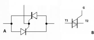
A two-color LED with two terminals consists of two back-to-back diodes connected in a common housing. Moreover, the body, or, more precisely, the lens, has standard dimensions and also only two terminals.
A special feature is that each LED terminal serves as the anode of one LED and the cathode of the second.
If you apply a plus to one pin and a minus to the second pin of the power supply, then one LED will be locked, and the second will light up, for example, green.
When the polarity of the power supply is changed, the green LED will be locked, and the red LED will light up.
Two-color LEDs are available in the following color combinations:
- Red Green;
- blue yellow;
- green - amber;
- Red Yellow.
How to connect a two-color LED with two terminals to a 220 V network
Such an LED is convenient to use on alternating current, since there is no need to use a reverse diode. Therefore, to connect a two-color LED to 220 V AC voltage, it is enough to add only a current-limiting resistor.
It is necessary to immediately make an amendment here that the nominal voltage in the network, which is also the same in the outlet, starting from October 2015, is no longer the usual 220 V, but 230 V. These and other data are reflected in GOST 29433-2014. The same standard provides permissible deviations from the rated voltage value of 230 V:
— nominal value 230 V;
— maximum 253 V (+10%);
— minimum 207 V (-10%);
— minimum under load 198 V (-14%).
Based on these assumptions, it is necessary to calculate the resistance of the current-limiting resistor so that it does not overheat and sufficient current flows through the LED for it to glow normally with the maximum permissible voltage fluctuations in the network.
Calculation of a current-limiting resistor
Therefore, although the nominal current value is 20 mA, we will take the calculated current value of a two-color LED as 7 mA = 0.007 A. At this value, it glows normally, since the brightness of the LED is not directly proportional to the current flowing through it.
Let's determine the resistance of the current-limiting resistor at a rated voltage in the socket of 230 V:
R = U/I = 230 V / 0.007 A = 32857 Ohm.
From the standard range of resistor values we select 33 kOhm.
Now let's calculate the power dissipation of the resistor:
P = I2R = 0.0072∙33000 = 1.62 W.
We accept a 2-watt resistor.
Let us recalculate for the case of the maximum permissible voltage at a given value of the resistor resistance:
I = U/R = 253 / 33000 = 0.0077 A = 7.7 mA.
P = I2R = 0.00772∙33000 = 1.96 W.
As you can see, when the voltage increases by an acceptable 10%, the current will also increase by 10%, however, the power dissipation of the resistor will not exceed 2 W, so it will not overheat.
When the voltage decreases by an acceptable amount, the current will also decrease. At the same time, the power dissipation of the resistor will also decrease.
Hence the conclusion: as an indicator of the presence of a mains voltage of 230 V, it is enough to just use a two-color LED with two terminals and a current-limiting resistor with a resistance of 33 kOhm with a dissipation power of 2 W.
If you look at such a semiconductor device when alternating current flows through it, you will see that both LEDs glow simultaneously.
In fact, they alternately flicker at a frequency of 50 Hz, but our eyes do not have time to track such fast flickers and give us a continuous image.
diodov.net
Flashing LED
In addition to constant light LEDs, there are also flashing ones. A single-color flashing LED is almost the same as a regular single-color LED, but it has an electronic current interrupter that periodically turns off the LED. That's why it blinks. There are two, three and multi-color flashing LEDs.
Inside such an LED there are several multi-colored LEDs, and an electronic switch circuit that switches them one by one.
A single- or multi-color flashing LED looks like a regular one - a transparent body and two outputs. It also needs to be connected via a current-limiting resistor.
It is curious that during blinking, in the intervals when the blinking LED goes out, the current through it decreases sharply. Therefore, flashing LEDs are sometimes used as pulse generators. In some diagrams, a flashing LED is designated as a regular one; in others, a switch symbol is added to its designation (Fig. 6).
Rice. 6. Designation on the diagrams and connection of the flashing LED.
A flashing LED can serve not only as an indicator, but also as a key to interrupt the current. For example, in order for a garland of several LEDs to blink.
If the garland consists of several LEDs connected in series, then for it to blink it is enough for one of these LEDs to be blinking. Figure 7 shows a diagram of the original signaling device for a passenger car.
Rice. 7. Diagram of an LED signaling device for a passenger car.
This is a parking warning device, it consumes a small amount of current from the car battery. The garland consists of four LEDs that need to be installed in the car headlights. The glow of LEDs at night is very noticeable, especially if they blink.
Therefore, a car parked in a dark courtyard ceases to be “invisible” to other cars or passers-by. And the risk of accidental damage to the machine is reduced.
In the circuit in Figure 7, there is only one blinking LED - HL2. The rest are ordinary. Since they are turned on, everything flashes sequentially. LEDs HL1, HL3, HL4 - any indicator, red, HL2 - any flashing red.
Two-color LED with three terminals
This product is in great demand. Essentially, these are several LEDs in a single housing, thanks to which the colors are mixed and the product will shine in different shades, which can light up sequentially. A two-color LED also comes with three terminals. The color changes based on how the current flows and in what direction. In this case, the diodes are connected in parallel. If the current flows in a straight direction, then one diode does not light up. The opposite happens if the current flows in the opposite direction.
The colors of the products can be: green, red, blue, etc., tones and shades are obtained by combining colors. The purpose of devices with LEDs is different. They are most often used in decoration, advertising lighting structures, and alarm systems. Also, products with multi-color LEDs are widely in demand in everyday life and electronic devices. They are found in phones, modern gadgets, cameras and other products. It's easy to see how the LED works. For example, when the battery is charged, the light glows green, and when the battery is discharged, it glows red.
It is important to know that an LED, which has three outputs, has more capabilities. This number of pins gives the right to autonomously control the operation of the crystals and obtain a more complete palette of shades when mixing colors
You can also adjust the brightness of the light using special devices (switches, PWM modulators)
Working principle of dual-color light-emitting diodes
The working principle of 2-pin components is simple. The color of the glow changes in parallel with the change in the polarity of the connection.
This means that the color is entirely dependent on the path the current takes. When a plus is applied to one of the terminals, one crystal begins to glow, the second is locked.
After changing the polarity, the closed one begins to glow, the luminous one is locked. This circuit is used in indicators operating on alternating voltage. Two-color diodes are connected in parallel and counter, the current is reduced by one resistor.
These elements are often installed in push-button switches, with the help of which the color of the glow changes.
Since the color of light-emitting diodes is unsaturated and dim, when combined, a shade is formed that is difficult for a person to determine. Another characteristic is the change in shade when looking at a light source from a variety of angles.
The situation changes when we are talking about a two-color LED with three pins in combination with a microcontroller. This scheme allows you to turn on each color separately and at the same time both.
When you connect a PWM regulator to the circuit, it becomes possible to change the brightness of each crystal to add additional shades.