The old uninsulated overhead power lines are gradually becoming a thing of the past. Currently, insulated wires are increasingly used on overhead lines. SIP cable stands for “self-supporting insulated wires”. They are used for the construction of new power lines, as well as for replacing overhead wires that do not have insulation.
Kinds
SIP cable is divided into main types depending on the material and design features. Each individual type of cable differs in diameter and number of cores, the presence of a neutral conductor, and insulation material. A common property of such SIP cables is the presence of insulation. In accordance with GOST, they are considered wires, but in fact they are cables.
Cable SIP-1
This type of cable consists of aluminum cores that are insulated with PET material. To briefly describe this type of insulation, we can say that PET is polyethylene terephthalate, a thermoplastic polyester material in the form of a synthetic fabric or film. This coating does not transmit ultraviolet rays. The neutral core is made in 2 versions: insulated and without insulation. SIP-1A is a cable with an insulated zero. This is indicated by the letter "A".
SIP-2
This type of cable has a similar design. The only difference is the insulation material. All cores are insulated with special polyethylene insulation (PET). This type of cable is used when installing power lines with voltages up to 1000 V. It is used for stringing main lines and auxiliary branches. It is advisable to use such a cable for northern regions and areas with temperate climates. It can also be used for summer cottages, provided the voltage is 380 V.
According to the standard, wires must withstand prolonged heating to a certain temperature. SIP-1A can withstand 70 degrees, and SIP-2A can operate at 90 degrees. When installing the wire, it is necessary to comply with the requirements for the smallest bending radius, which, according to the rules, must be more than 10 times the cable diameter.
SIP-3
This cable option has significant differences. Its design consists of a steel core with an aluminum braid, which consists of an alloy of aluminum, magnesium and silicon. On the outside, the wire has PET insulation, which does not transmit ultraviolet rays. This 1-core wire is used for the construction of 20 kilovolt electrical lines. It is recommended for use in different types of climates, except arctic and extreme continental ones. According to the standard, the normal operating temperature should be 70 degrees; a temperature of -20 +90 degrees is allowed.
SIP-4
This cable is made of several pairs of cores. There is no neutral wire. At the end of the designation there is a marking “H”, which indicates that the core material is an alloy. If there is no letter in the designation, then the core is made of pure aluminum. The outside of the cores is insulated with thermoplastic PVC, which is UV resistant.
SIP-5
The design of this brand of wire is similar to the SIP-4 cable, but differs in the insulation material, which is made of PET. This makes it possible to increase the duration of exposure to the permissible temperature by 30%. The SIP-5 cable is used for the construction of 2.5 kilovolt power lines, as well as for supplying to buildings, street lighting, and branches to country houses. The use of SIP-5 is recommended for areas of temperate and cold climates.
The technical properties of various types of SIP wires are shown in the table.
Marking
SIP cable is designated using numbers, letters and insulation colors. Let's look at an example of the designation of a SIP-1 wire and decipher it:
SIP – 1 – 3x70 + 1x95 – 0.6 / TU 16-705.500 – 2006
The cable has 3 phase conductors with a cross-section of 70 mm 2 , one conductor without insulation, with a cross-section of 95 mm 2 . The operating voltage of the cores is 0.6-1 kilovolt.
Cable marking is carried out according to certain rules, as follows:
- The phase cores are designated by numbers, stripes, printing or embossing methods.
- The zero core is not indicated.
- Instead of numbers and letters, a colored stripe more than 1 mm wide can be used.
- Auxiliary lighting cores are designated B1, B2, B3.
- The cable is marked every 50 cm along its entire length.
- Designations of standard sizes: sign width more than 2 mm, height 5 mm.
- Auxiliary control conductors may not have markings.
- The marking must be resistant to ultraviolet rays and retained throughout its service life.
By deciphering the cable designation according to its marking, you can navigate its selection and correct use.
Cable properties
The technical data of the cable must be standardized according to GOST R 52373 - 2005. This standard defines the use of SIP cable for power lines no higher than 35 kilovolts. The core cross-section can be up to 240 mm 2. In sections of the power transmission line, the diameter of the main cable is made higher than the cross-section of the cores of the branch cable. The technical properties of the cable allow it to be installed for organizing street lighting. For such tasks, a SIP cable with 25 mm 2 cores is suitable.
The standard reflects the characteristics of the limit values. If any parameters do not match GOST, then such a wire cannot be used.
Basic parameters of the wire according to the standard:
- Maximum permissible load. The larger the cross-section, the higher the permissible load.
- Highest operating temperature.
- Temperature limit in critical mode (130 degrees).
- Allowable bending radius (at least 10 core diameters).
- Warranty period 3 years.
- Service life, subject to compliance with operating requirements, is more than 40 years.
SIP-4 cable marking by color
5.2.7.2 The main conductors of self-supporting insulated wires must have a distinctive designation in the form of longitudinally pressed relief strips on the insulation , as shown in Figure B.1 (Appendix B), or numbers 1, 2, 3, embossed or printed. An insulated zero load-bearing core should not have a distinctive marking. The distinctive designation also be made in the form of colored longitudinal stripes with a width of at least 1 mm. The color of the stripes should be contrasting with black. Auxiliary conductors for lighting circuits must have a distinctive designation: “B1”, “B2” or “B3”, embossed or printed. Marking with numbers and letters, embossed or printed, should be done at intervals of no more than 500 mm. The height of numbers (letters) must be at least 5 mm, width - at least 2 mm (for number 1, the minimum width is 1 mm). Auxiliary conductors for control circuits may not have a distinctive marking. The distinctive sign, whether printed or in the form of colored longitudinal stripes, must be resistant to solar radiation throughout its entire service life.
Figure B.1 1(first core) - one strip; 2 (second core) - two strips; 3 (third core) - three stripes; (zero core) - without designation. Dimensions a,b,h are for reference.
From the above it follows: if, for example, on a Chinese or Russian SIP-4 2x16 mm one of the cores has a colored stripe , this means it is a “phase” . A vein that has no distinctive images, correspondingly “zero” .
Source: radiolubitel.net
ElektroMaster.org DIY repair and maintenance of household electrical appliancesTips, guides..
Yandex.Direct
A three-phase power supply system is a special case of multiphase electrical circuit systems in which sinusoidal EMFs of the same frequency created by a common source operate, shifted relative to each other in time by a certain phase angle.
Thus, each such EMF is in its own phase of the periodic process, and therefore is often called simply a phase. Also called “phases” are conductors - carriers of these EMFs. In three-phase systems, the shear angle is 120 degrees.
Phase conductors are designated in the Russian Federation by the Latin letters L with a digital index 1...3, or A, B and C[1].
Common designations for phase wires:
Russia, EC (above 1000 V) Russia, EU (below 1000 V) Germany Denmark
| A | L1 | U1 | R |
| B | L2 | V1 | S |
| C | L3 | W1 | T |
Graphic representation of phase currents versus time
Vector diagram of phase currents. Symmetrical mode.
A significant contribution to the development of three-phase systems was made by M. O. Dolivo-Dobrovolsky, who conducted a number of experiments with an induction electric motor and identified a number of advantages of the three-phase system in relation to other systems.
- Economical. Cost-effective transmission of electricity over long distances.
- Compared to systems with a large number of phases, the cost-effectiveness is manifested in the need for fewer linear conductors, which reduces the cost of conductive materials.
- Less material consumption of 3-phase transformers.
3-phase motors (asynchronous and synchronous) are simpler in design than single- or 2-phase DC motors and have high efficiency indicators.
Thanks to these advantages, three-phase systems are the most common in modern power generation.
Connection diagrams for three-phase circuits
Star
Star connection of windings
Existing types of line voltage protection that can be found on sale in electrical stores. As required by modern standards, installation takes place on a DIN rail.
A star connection is such a connection when the ends of the phases of the generator windings (G) are connected to one common point, called the neutral point or neutral. The ends of the phases of the receiver windings (M) are also connected to a common point. The wires connecting the beginning of the phases of the generator and receiver are called linear. The wire connecting two neutrals is called neutral.
A three-phase circuit with a neutral wire is called a four-wire circuit. If there is no neutral wire, a three-wire one.
If the resistances Za, Zb, Zc of the receiver are equal to each other, then such a load is called symmetrical.
Fault if the neutral wire breaks
A special feature of a symmetrical load in a three-phase system is that the consumer is supplied with phase voltage even in the absence of a neutral wire.
In the case of an asymmetrical load, when the working zero is broken, the load is under linear voltage, which is often the reason for the failure of consumer electronics in apartment buildings.
Since the consumer’s resistance remains constant, according to Ohm’s law, as the voltage increases, the current that the consumer will have will be much greater than the maximum permissible value, which will cause combustion and/or failure of the powered electrical equipment.
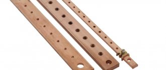
- Busbars for distributing neutral wires and grounding wires when connected by a star. One of the advantages of star connection is savings on the neutral wire, since only one wire is required from the generator to the point of separation of the neutral wires near the consumer
The relationship between linear and phase currents and voltages
The voltage between the line wire and the neutral (Ua, Ub, Uc) is called phase. The voltage between two linear wires (UAB, UBC, UCA) is called linear. To connect the windings with a star, with a symmetrical load, the relationship between linear and phase currents and voltages is valid:
The relationship between linear and phase currents and voltages
To connect the windings in a triangle, with a symmetrical load, the relationship between linear and phase currents and voltages is valid:
Common voltage standards
RF and CIS countries EU Italy USA
| Voltage (phase/line) | 220/380 | 230/400 | 240/420 | 127/220 |
| Frequency | 50 Hz | 50 Hz | 50 Hz | 60 Hz |
Marking
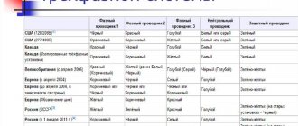
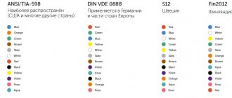
Conductors belonging to different phases are marked with a separate color. This is done for ease of maintenance, installation and repair of electrical equipment. Chain markings vary from country to country.
| Phase APhase BPhase C Neutral Ground US (120/208V)[2] | Black | Red | Blue | White or gray | Green |
| USA (277/480V) | Orange | Brown | Yellow | White or gray | Green |
| Canada | Red | Black | Blue | White | Green |
| Canada (Isolated three-phase installations) | Orange | Brown | Yellow | White | Green |
| UK (since April 2006) | Red (Brown) | Yellow (formerly White) (Black) | Blue (Grey) | Black (Blue) | Green-yellow |
| Europe (since April 2004) | Brown | Black | Grey | Blue | Green-yellow |
| Europe (until April 2004, depending on country) | Brown or Black | Black or Brown | Black or Brown | Blue | Green-yellow |
| Europe (Tire designation) | Yellow | Green | Red | ||
| Russia (USSR)[3] | Yellow | Green | Red | Blue | Green-yellow (on older installations – Black) |
| Australia and New Zealand | Red | Yellow | Blue | Black | Green-yellow (on older installations – Green) |
| South Africa | Red | Yellow | Blue | Black | Green-yellow (on older installations – Green) |
| Malaysia | Red | Yellow | Blue | Black | Green-yellow (on older installations – Green) |
| India | Red | Yellow | Blue | Black | Green |
Notes
- ↑ GOST 2.709-89, current in the Russian Federation, prescribes the designation of phase conductor circuits of three-phase alternating current: L1, L2, L3, and at the same time allows the designations A, B, C.
- ↑ Since 1975, the National Electrical Code (USA) has not regulated the color designation of phase wires. The colors shown in the table are generally accepted in use.
- ↑ According to the PUE for three-phase alternating current: buses of phase A are designated in yellow, phases B in green, phases C in red (in alphabetical order of the initial letters in the name of the colors: Zh, Z, K)
wikipedia.org
Source: https://ElektroMaster.org/tryohfaznaya-sistema-elektrosnabzheniya-v-tom-chisle-markirovka-provodov.html
Properties, markings and characteristics of SIP cable
Depending on the brand, the SIP electrical installation cable is designed to transmit electric current in networks with a voltage of 0.4 - 1, or 10 - 35 kV. The lines laid with this cable compare favorably with their predecessors in cost and do not require highly qualified personnel for installation and operation. What a SIP electric wire is can be understood at first glance - there is insulation on its cores.
Application, advantages and disadvantages
Due to the presence of insulation, SIP has a fairly wide scope of application. It is most often used to introduce electricity into a building, and thanks to the outer layer of insulation, additional measures and devices are not required when passing through walls. Also, a self-supporting insulating wire can be used for local wiring of networks throughout the facility or when connecting subscribers to the lines of an energy supply organization. A separate area of application for SIPs are trunk lines that provide power supply to entire villages or distribution substations.
Compared to other brands of cable and wire products, SIP has a number of advantages, namely:
- SIP wire has significantly lower reactance compared to bare wires;
- Does not require the installation of additional insulators at points of attachment to supports, walls and when entering the building due to the presence of an insulating layer;
- Takes up less space due to the fact that the wires are collected together;
- Not subject to corrosive destruction due to the presence of a protective layer;
- Not afraid of overlap of adjacent phases under strong wind loads;
- Makes it difficult to illegally take power by throwing on wires;
The disadvantages of SIP wire include the greater weight of a linear meter, which is why the spans need to be reduced and supports installed more often. As well as the need to arrange additional insulation for certain categories of premises and consumers.
Methods of application and decoding of markings
The abbreviation itself, used as a name, stands for Self-Supporting Insulated Wire, which already determines its main characteristics. Marking on the SIP wire can be applied alphanumerically and with color marks, in compliance with the following requirements:
- If color marking is used, it is applied in stripes no less than 1 mm wide. For a self-supporting neutral wire, blue is used.
- Alphanumeric symbols are extruded onto the insulation or printed in the form B1, B2, B3.
- Each sign is at least 2 mm wide and 5 mm high.
- The distance between marking repeats is 50 cm.
- The zero core is not marked.
This is an important point - for example, a cable may have three cores color coded yellow, blue and red, and the fourth completely black. Zero in this case is the one that is completely black, and not marked with a blue stripe.
In addition to designating the phase and neutral wires, the marking contains information about the number of current-carrying wires and the size of their cross-section. These designations are as follows:
From the above designation it is clear that this is a cable with three phase conductors insulated with cross-linked polyethylene with a cross-section of 120 mm² and one neutral conductor without insulation, with a cross-section of 95 mm². This SIP wire is designed for voltages up to 1000 Volts and is made according to TU 16-705.500-2006.
Color designation of cores according to PUE
PUE 7 (Electrical Installation Rules) in terms of color and digital identification of insulated or non-insulated conductor cores in paragraph 1.1.29 is based on GOST R 50462. This document is called accordingly: “Identification of conductors by means of colors and alphanumeric designations.”
Attention! According to GOST R 50462, only the following colors can be used for painting insulation: black, white, turquoise, brown, pink, red, gray, orange, purple, yellow, blue (light blue, cyan), green. In this case, the same color of the insulating coating (or a certain combination of colors) must be maintained along the entire length of the core.
Yellow and green should only be used together as yellow-green colors. Identification can also be done using colored tags. It is better to do this along the entire length of the conductor. Bare conductors must be color coded at connections and ends.
Accepted color marking in AC circuits
In single-phase circuits, it is preferable to identify the phase by a brown color. In three-phase, it is recommended to use the following colors to designate phase conductors:
- phase 1 (P1 or L1, A) – brown;
- phase 2 (Ф2 or L2, В) – black;
- phase 3 (F3 or L3, C) – gray.
In switchgears (RU), different phases according to the PUE correspond to tires of the following color:
- phase 1 – yellow;
- phase 2 – green;
- phase 3 – red.
In addition to the recommended colors, conductors with different colors are used as phase conductors:
- pink;
- red;
- white;
- turquoise;
- violet;
- orange.
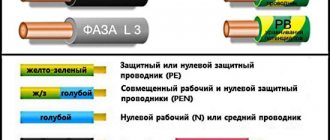
Attention! In order to identify the neutral (neutral conductor, N), it is regulated to use a conductor with a blue insulating coating. Protective conductors, which serve to increase the level of electrical safety, are generally designated PE and have a two-color yellow-green color (in AC and DC circuits). This color combination is not used for other purposes.
GOST R 50462 requires that any 1.5 cm of insulation along the entire length of the protective conductor be painted in one of the colors by no less than 30%, but no more than 70%. And the remaining surface should be covered by another.
As PEN-type protective conductors (combine the functions of a neutral and a grounding conductor), wires with an insulating coating of two types can be used:
- yellow-green;
- blue
In the first case, when installing PEN-type conductive wiring, it is necessary to additionally mark it (at the joints and at the ends) with blue, and in the second case, on the contrary, with yellow-green. Wires with blue insulation can also serve as grounded phase conductors in single-phase and three-phase circuits.
DC circuits
In DC networks, it is customary to use wires with brown insulation as the positive pole conductor (+), and with gray insulation for the negative pole (-). The middle conductor (the core connected to the midpoint in the DC circuit) is usually designated blue.
For grounded positive and negative pole conductors, blue is also the preferred color. In order not to confuse them with the middle conductor, you will need to use additional alphanumeric designations during installation. They are applied along the edges and at joints.
In DC network switchgears, positive conductors correspond to red buses, and negative conductors are colored blue. If there is a medium working tire (M), it is painted blue.
Advantages of SIP wire
Insulated wires are superior in all respects to their predecessors, which did without a protective sheath:
- Installation speed. Instead of running 4 separate wires, you only need to run one cable.
- Ease of connection - in this regard, an electrical wire without insulation requires increased attention and careful double-checking.
- Qualification of installers. During installation, you do not need to accurately check the distance between the wires to avoid a short circuit.
- Installation cost. There is no need to use insulators - accordingly, their purchase and installation are removed from the expense item.
- The ability to connect new points without disconnecting the entire line - special clamps have been developed for such wires that pierce the insulation and are pressed tightly against the current-carrying core.
Manufacturers claim that the cable design makes it possible to almost completely eliminate the theft of electricity. Of course, we are not talking about complete protection of the cores, but making an unauthorized connection to them is indeed more difficult.
For more information about the characteristics and use of the cable, watch this video:
Color marking of single-phase network wires
When purchasing single-core or multi-core cables for AC power networks, that is, for household electrical outlets, lamps and wiring, we see a certain number of copper wires braided with an insulating layer.
The colors of the internal insulation of the wires are not random (although some would-be electricians connect them at will), the purpose of the article is to consider the role of wires with a certain color.
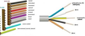
Single-phase wire colors
- Phase line L - brown, black, red, gray, white.
- Neutral wire N - blue
- Protective PE - yellow-green
- The insulation of all cable conductors is usually white
Designation of wires in electrical
In electrical networks and AC installations, wires are divided into 3 types:
- phase wire - designation L (if there are more phases, L1, L2, L3)
- neutral conductor - designation N
- protective conductor - PE
Attention! In old buildings and networks laid by inebriated electricians, the colors of the conductors may have a different meaning, this should always be kept in mind.
Phase line color L
This cable is most often brown or black, but it can also be red, gray, white... It all depends on the number of wires in the cable and the manufacturer of the cable.
In principle, only prohibited colors for a phase conductor are unacceptable - blue and yellow-green. The phase wires are directly connected to the transformer coil.
In the case of domestic houses, this means that the electrical voltage between ground and cable of this type is 220 V.
Neutral line color N
Neutral conductor N is marked in blue. This is a wire that, like a phase wire, is necessary for the proper functioning of an electrical device. However, this is where the similarities between these wires end.
Useful: Programmable timer - time relay for 220V
The N conductor is connected to the neutral point of the power network transformer and is grounded, which means the ground voltage should be 0 V.
As a result, touching the neutral conductor will not cause an electric shock (in theory). But you should always be careful when it comes to electricity.
It is not known exactly how the electrician performed the installation and whether the network complies with the standards.
PE protection line color
The protective conductor is marked in yellow and green. As the name suggests, it has the task of protecting a person from electric shock.
The protective conductor is literally connected to the ground, the main protective line ends with a wire or flat steel rod buried in the ground.
If there is no connection to ground, the protective conductor is connected to the neutral conductor N in the fuse box in the apartment (or in each electrical outlet separately, when there are no protective conductors in the entire apartment - this applies mainly to older wiring).
If the cable does not contain the required color
It may happen that the purchased electrical cable does not have the color that we want to use in the electrical installation, for example brown. What to do then?
Simply take a wire of a different color (for example, gray) and connect it to a neutral conductor. Then we take electrical tape (or heat shrink tubing of the desired color) and mark the cable at both ends. Thanks to this, we will know that a change has been introduced here.
Video lesson on GOST colors
2– 5,00Loading…
CLICK HERE AND OPEN COMMENTS
Source: https://2shemi.ru/tsvetovaya-markirovka-provodov-odnofaznoj-seti/
SIP wire design
To know how to choose the right cable, you must first decide what designs it comes in. The first symbols of the marking, immediately following the abbreviation, indicate the type of SIP cable, which is marked as 1, 1A, 2, 2A, 4, 4n, 5 and 5n. They show what the neutral wires are made of, whether there is insulation on them and how the self-supporting property of the cable is ensured (steel core inside the neutral wire or the strength of the overall structure)
SIP-1 and SIP-1A
These brands of SIP electrical wire are almost identical in their characteristics. The only difference between them is the presence of insulation on the neutral core: SIP-1 does not have it, but SIP-1A does. Moreover, the neutral conductor itself has a steel core and can be of a larger, equal or smaller cross-section than the phase wires, depending on the brand and purpose of the cable. The insulation material is thermoplastic polyethylene with an operating temperature of -60 to +50 C°, which can withstand prolonged heating up to +70 C° without compromising its properties. Number of cores – 2-4.
Colors for 220V and 380V networks
Installation of single- and three-phase electrical networks is facilitated if the wiring is made with multi-color wire. Previously, a flat two-core white wire was used for single-phase residential wiring. During installation and repair, to eliminate errors, it was necessary to ring each core individually.
Read also: Signs of estrus in pigs
The production of cable products with colored cores in different colors reduces the labor intensity of the work. To indicate phase and zero in single-phase wiring, it is customary to use the following colors:
- red, brown or black – phase wire;
- other colors (preferably blue) – neutral wire.
The phase markings in a three-phase network are slightly different:
- red (brown) – 1 phase;
- black – 2 phase;
- gray (white) – 3 phase;
- blue (cyan) – working zero (neutral)
- yellow-green – grounding.
Domestic cable products comply with the standard for core coloring, so a multiphase cable contains differently colored cores, where the phase is white, red and black , the neutral is blue , and the ground is yellow-green conductors.
When servicing networks installed according to modern standards, it is possible to accurately determine the purpose of the wires in the junction boxes. If there is a bundle of multi-colored wires, the brown one will definitely be phase. The neutral wire in the distribution boxes has no branches or breaks. The exception is branches to multi-pole switching devices with complete circuit breaking.
Core cross-section and technical characteristics of wires
When making preliminary calculations, it is necessary to take into account the cross-sectional area and weight of the wire - these data can be taken from comparative tables.
If you are calculating the connection of a SIP cable to a house, you need to carefully measure the distance from the street pole to the point where the wire is inserted - if it is more than 25 m, then you will have to place an additional support under the selected cable.
Sections of conductors of wires of brands SIP-1 and SIP-2:
Core cross-section and characteristics of single-core SIP wire:
Cross section of wires SIP-4 and SIP-5:
The main technical characteristics of the SIP wire are as follows:
For more information about the different types of SIP cable and its installation, see this video:
Electrical cable made in Russia
Since the end of the twentieth century, domestic industry (and Sevkabel) has shown the first electrically conductive products. In a short period of time, SIP wire has become popular both in everyday life and in production. This was facilitated by its technical operating parameters.
Experts say that the cost of this wire is generally 25% more than the cost of producing wires without an insulated coating, but the strength of SIP is 70% higher. The Russian government has adopted a program under which enterprises of RAO UES of Russia are transferred to power supply through the operation of self-supporting insulated wires, overhead or otherwise.
This type of cable takes first place when it is necessary to distribute or transform electrical energy. In networks up to 1000 volts (household consumers), SIP grades 1 or 5 are used; for electricity transformation lines up to 20 kV, SIP grade 3 is used. In the territory of the Russian Federation, SIP wire is used for transformation and branches of electrical energy, connecting electricity consumption facilities.
Briefly about the main thing
SIP brand cables are the next generation of wires for overhead power lines, significantly increasing the efficiency of their operation. In domestic use it is mainly used when laying lines from the transformer to the consumer and making branches from them. One of the main advantages when using it is the ease of installation and operation, which allows a person to operate it without much experience in such work. But in any case, we must remember that all manipulations to connect electrical wiring to the network must be carried out by qualified electricians.
Source: yaelectrik.ru
Laying conditions
Due to the fact that laying SIP does not require any special skills, it can be done either at home or by the enterprise’s own resources without the involvement of a specialized organization. Laying can be carried out both on supports and on structural elements of buildings and structures. As a rule, fastening to walls is much easier than on a free-standing support.
Therefore, consider the conditions for installing SIP wire on reinforced concrete supports:
- Since the self-supporting insulating wire has an insulated sheath, it is important to provide a suspension that prevents damage to the dielectric layer. To do this, plastic rollers, grips and thimbles are installed, along which the wire can move freely.
- During the installation process, it is forbidden to drag the SIP along the ground or tree branches, as these can damage its insulation.
- To join different sections of SIP, sealed piercing-type clamps are used. Thanks to this design, it is possible to tap a line from an existing one even under voltage.
- Before fixing it on the support, the SIP wire must be pulled out through the moving element (for SIP brands from 1 to 3 using a dynamometer until the normalized load is set). After stretching, it is fixed at the fixation points.
All fasteners are factory-made, so they can be found complete with self-supporting insulating wire, which will greatly simplify the task.
Rice. 6: Example of fastening a SIP wire to a support
SIP cable. Types and device. Labeling and application. Installation
The old uninsulated overhead power lines are gradually becoming a thing of the past. Currently, insulated wires are increasingly used on overhead lines. SIP cable stands for “self-supporting insulated wires”. They are used for the construction of new power lines, as well as for replacing overhead wires that do not have insulation.
Kinds
SIP cable is divided into main types depending on the material and design features. Each individual type of cable differs in diameter and number of cores, the presence of a neutral conductor, and insulation material. A common property of such SIP cables is the presence of insulation. In accordance with GOST, they are considered wires, but in fact they are cables.
Cable SIP-1
This type of cable consists of aluminum cores that are insulated with PET material. To briefly describe this type of insulation, we can say that PET is polyethylene terephthalate, a thermoplastic polyester material in the form of a synthetic fabric or film. This coating does not transmit ultraviolet rays. The neutral core is made in 2 versions: insulated and without insulation. SIP-1A is a cable with an insulated zero. This is indicated by the letter "A".
SIP-2
This type of cable has a similar design. The only difference is the insulation material. All cores are insulated with special polyethylene insulation (PET). This type of cable is used when installing power lines with voltages up to 1000 V. It is used for stringing main lines and auxiliary branches. It is advisable to use such a cable for northern regions and areas with temperate climates. It can also be used for summer cottages, provided the voltage is 380 V.
According to the standard, wires must withstand prolonged heating to a certain temperature. SIP-1A can withstand 70 degrees, and SIP-2A can operate at 90 degrees. When installing the wire, it is necessary to comply with the requirements for the smallest bending radius, which, according to the rules, must be more than 10 times the cable diameter.
Main manufacturers
To avoid troubles when purchasing a wire or cable, you should pay attention not only to the main parameters of the product, but also to its manufacturer. Since low-quality models may have a smaller cross-section, low dielectric resistance to various types of influence, etc. If you have already purchased a self-supporting insulating wire and are not sure of its quality, check whether the cross-section corresponds to that stated in the passport. How to determine the cross section at home is described in the corresponding article - https://www.asutpp.ru/kak-opredelit-sechenie-provoda-ili-zhil-kabelya.html.
If you are just going to buy SIP, pay attention to the following manufacturers:
- Kama cable;
- Rybinskcable;
- GC "Sevkabel"
- Moscabel.
Using wires from the above-mentioned factories, you can be sure that they comply with the declared characteristics.
Two questions Blue phase. black zero. We provide light almost for free.
Good day. With your permission, I’ll digress a little from the topic.
My brother and neighbor decided to install electricity on our own property. My brother convinced me that according to the new laws I was required to pay 550 rubles. provide 15 kW. All kinds of offices charge 50 thousand rubles to install light on the site. but we decided to save money.
Mosenergo received a piece of paper for 550 rubles. In the store we bought a meter, a box on a pole, machines, SIP4, 15 meters. — budget 6 thousand rubles. Since the main line runs through opposite sections, we had to put up one pole between us to throw the SIP across the road. (+5 thousand rubles for each) if the light was provided by the office, then the cost of the pole would definitely be added.
I assembled the boxes with meters myself and hung them on my pole, but two SIP4 cables across the road were thrown onto our pole by the shabatniks who installed the pole. AND NOW ABOUT THE BLUE PHASE and BLACK ZERO. It's time to get SIP4 into our boxes. I look at the cable: 4 wires with a green stripe, red, blue and one without stripes, i.e. completely black. I decided without any doubt that blue should be ZERO. but my brother led me into doubt (he doesn’t know anything about electrics) they called the shabashniks who erected the pole, they unanimously said ZERO_BLACK. i.e. without markings! As a result, black became zero, now we are waiting for the inspector who must accept the fulfillment of the Technical Conditions. those. check how we mount everything and then connect the second ends of the SIP.
- Is zero really black on SIP? blue phase?
- Is it possible to hang boxes on a pole if the pole is personal?
- What kind of scams can you expect from the inspector? Thanks for any comment.
Source: www.mastergrad.com
Grounding
The yellow-green wire is grounding. In circuit diagrams, grounding conductors are marked with the letters PE. In some older houses there are PEN wires in which the grounding is combined with the neutral conductor. If the cable was pulled according to the rules, wires with blue insulation were chosen, and only the ends and places of twists were yellow-green (thermal tubes were put on them). The thickness of the “zero” and grounding may be different. Often the thickness of these two conductors is less than the thickness of the phase conductor; this occurs when connecting portable devices.
When it comes to laying electrical wiring in multi-storey buildings and industrial premises, the norms of PUE and GOST 18714-81 come into force, requiring the mandatory installation of protective grounding. Grounding must have minimal resistance to compensate for the consequences of faults on the line and prevent harm to human health. That is, compliance with the standards for color marking of PUE wires is of paramount importance.
What color is the neutral wire? Electrical standards specify that its insulation may be blue, blue with a white stripe, or light blue. Such markings will be present in a cable with any number of cores. In circuit diagrams, “zero” is marked with the letter N; the circuit is closed to it. Sometimes it is called “minus”, and the phase one is called “plus”.
The color of the phase is what is of paramount importance for an electrician: handling conductive conductors requires care and knowledge. The slightest touch of the phase can lead to injury. There are many colors for phase wires marked in the form of the letter L in electrical wiring; the ban only applies to the use of blue, yellow and green colors. If the cable is three-phase, the serial number of the core is added to the letter L.
When a single-phase circuit is separated from a three-phase one, electricians use cables with strictly the same colors, monitoring the color of the phase and zero in the wire. Before starting work, they determine for themselves how the different wires will be connected, and then follow the chosen color. Sometimes thermal casings are fused onto them or several turns of colored appropriate electrical tape are wound.
- black phase wires are used in power circuits operating with direct and alternating current;
- red color - used in control circuits designed for alternating current;
- with orange color - found in interlock control circuits powered from external sources.
How to determine the purpose of a wire - neutral or ground?
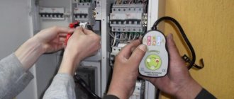
LN marking in electrical engineering is not always observed in old buildings, so the question arises of independently distinguishing between the neutral wire and the ground wire. When the circuit is closed, an electric current passes through the “zero”. The grounding wire has only a protective function, and in “normal” mode no current flows through it.
You can find out whether it is “zero” or “ground” like this:
- Use an ohmmeter, first turning off the voltage between the measurement points. The resistance on the ground wire will not exceed 4 ohms.
- Use a voltmeter and sequentially measure the voltage between the “phase” and other wires (the method is suitable for three-core cables). The ground wire will give the greatest value.
- If the colors of the “phase”, “zero” and “ground” wires are unknown, and you need to find out the voltage between the ground wire and some known grounded object (for example, a heating radiator), a voltmeter is also useful. True, when connecting the “earth” and a grounded object, it will not show anything. But a small voltage will be reflected in its indicator if you do the same with the “zero” wire.
In a two-core cable there will always be only a phase and neutral wire.
