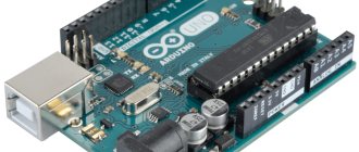
Instructions for using Arduino with SPI interface
We will need:
- Arduino UNO or other compatible board;
- shift register 74HC595;
- 8 LEDs (for example, from this set);
- 8 resistors of 220 Ohms each (I recommend purchasing a set of resistors with ratings from 10 Ohms to 1 MOhm);
- connecting wires (for example, this is a good set);
- bread board;
- personal computer with Arduino IDE development environment.
1Description of the SPI serial interface
SPI – Serial Peripheral Interface or “Serial Peripheral Interface” is a synchronous data transfer protocol for interfacing a master device with peripheral devices (Slave) . The master device is often a microcontroller. Communication between devices occurs over four wires, which is why SPI is sometimes called a “four-wire interface.” These are the tires:
| Name | Purpose of the SPI bus |
| MOSI (Master Out Slave In) | data transmission line from master to slave devices; |
| MISO (Master In Slave Out) | transmission line from slave to master; |
| SCLK (Serial Clock) | synchronization clock pulses generated by the master device; |
| SS (Slave Select) | slave selection line; when the line is logical “0”, the slave device “understands” that it is now being addressed. |
There are four data transfer modes ( SPI_MODE0, SPI_MODE1, SPI_MODE2, SPI_MODE3 ), determined by the combination of the polarity of the clock pulses (we work at the HIGH or LOW level), Clock Polarity, CPOL , and the phase of the clock pulses (synchronization on the rising or falling edge of the clock pulse), Clock Phase, CPHA . The last column of the table contains explanatory illustrations. Samples on them indicate the moments when data on the line should be ready and read by devices. The letter Z indicates that the state of the data on the line is unknown or unimportant.
| Mode | Clock Polarity (CPOL) | Clock phase (CPHA) | Mode Diagram |
| SPI_MODE0 | 0 | 0 | |
| SPI_MODE1 | 0 | 1 | |
| SPI_MODE2 | 1 | 0 | |
| SPI_MODE3 | 1 | 1 |
The SPI interface provides several options for connecting slave devices: independent and cascaded . When connected independently to the SPI bus, the master device accesses each slave device individually. With a cascade connection, the slave devices operate one by one, as if in a cascade.
Types of device connection for operation via the SPI interface: independent and cascade
Installing drivers
On Windows, the drivers will be installed automatically when you connect the board if you used the installer. If you downloaded and extracted the Zip archive or for some reason the board is not recognized correctly, follow the procedure below.
- Click on the Start menu and open Control Panel.
- Go to the System and Security section. Then click "System". Then open Device manager.
- Look under Ports (COM & LPT). You should see an open port named "FT232R USB UART". If the COM and LPT section is missing, look at the Other Devices, Unknown Device section.
- Right-click on the FT232R USB UART port and select the "Update Drivers..." option.
- Then select the option “Browse this computer for driver software.”
- Finally, find the FTDI USB Drivers directory, which is located in the Drivers folder of the Arduino program.
- Windows will then complete the driver installation.
2Implementation of the SPI interface on Arduino family boards
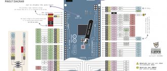
In Arduino, SPI interface buses are located on specific ports. Each board has its own pin assignment. For convenience, the pins are duplicated and also placed on a separate ICSP connector (In Circuit Serial Programming, programming a device included in the circuit using a serial protocol). Please note that there is no slave selection pin - SS on the ICSP connector, because it is assumed that the Arduino will be used as a master device in the network. But if necessary, you can assign any digital pin of Arduino as SS.
The figure shows the standard correspondence of pins to SPI buses for Arduino UNO and Nano.
Implementation of the SPI interface on Arduino UNO and Arduino Nano boards
An example of using Arduino SPI in a project with a pressure sensor
To implement the project we need an Arduino, a pressure sensor, a breadboard and wires. An example of sensor connection is shown in the figure.
Using the SCP1000 sensor, it is possible to recognize parameters such as pressure and temperature and transmit these values via SPI.
Basic elements of a program sketch
First of all, the sensor registers are registered in the code using setup(). Several values are returned from the device - one in 19 bits for the received pressure, another in 16 bits for the temperature. After this, two temperature bytes are read and pressure is read in two stages. First, the program takes the three most significant bits, then the next 16 bits, after which, using a bit shift, these two values are combined into one. Real pressure is the 19-digit value divided by 4.
const int PRESSURE = 0x1F; // first stage of pressure determination (three most significant bits are detected)
const int PRESSURE_LSB = 0x20; // second stage, which defines 16 bits for pressure
const int TEMPERATURE = 0x21; //16 bits for temperature
To read the temperature data and convert it to Celsius, the following code element is used:
int tempData = readRegister(0x21, 2);
float realTemp = (float)tempData / 20.0; // to determine the real temperature value in Celsius, you need to divide the resulting number by 20
Serial.print(“Temp
="); Serial.print(realTemp); Reading pressure bits and combining them: byte pressure_data_high = readRegister(0x1F, 1); pressure_data_high &= 0b00000111; unsigned int pressure_data_low = readRegister(0x20, 2); long pressure = ((pressure_data_high << 16) | pressure_data_low) / 4; //definition of pressure in Pascals.
3Standard library for working via the SPI interface
A special library has been written for Arduino that implements the SPI protocol. It is installed along with the Arduino IDE. It is connected like this: at the beginning of the program we add #include SPI.h .
To start using the SPI protocol, you need to set the settings and then initialize the protocol using the SPI.beginTransaction() . You can do this with one instruction: SPI.beginTransaction(SPISettings(14000000, MSBFIRST, SPI_MODE0))
This means that we initialize the SPI protocol at a frequency of 14 MHz, data transmission occurs starting from MSB (most significant bit), in SPI_MODE0 mode.
After initialization, select the slave device by moving the corresponding SS pin to the LOW state. Then we transfer the data to the slave device using the SPI.transfer() . After transmission, return SS to the HIGH state.
Timing diagram of the SPI interface
Work with the protocol is completed with the SPI.endTransaction() .
It is advisable to minimize the transfer time between the SPI.beginTransaction() and SPI.endTransaction() instructions to avoid problems if another device tries to initiate a data transfer using different settings.
If you plan to use standard Arduino pins in your sketch, you don’t have to describe them at the beginning of the program, because they are already defined in the library itself and have the following names:
#define PIN_SPI_SS (10) #define PIN_SPI_MOSI (11) #define PIN_SPI_MISO (12) #define PIN_SPI_SCK (13)
These pins are defined in the file pins_arduino.h, which is located in the path %programfiles%\arduino-(version)\hardware\arduino\avr\variants\ (if you installed the program in the standard location). That is, for example, to lower the slave selection pin to the “0” state, you can write:
digitalWrite(PIN_SPI_SS, LOW);
Avrdudeprog
Avrdudeprog is a utility from a Russian programmer that is a convenient wrapper for avrdudue . You can download AVRDUDE_PROG from the official website (direct download link, just in case, a mirror on my POISON and FTP of this site). As part of this lesson, the program can do the following:
- Read/write/clear flash memory
- Read/write/clear eeprom memory
- Complete chip cleaning
- Fuses and lockbits calculator (read/write)
A more detailed review of avrdudeprog can be found here. Let's take a look at the fuse calculator. Select your microcontroller and programmer (you can add other models of microcontrollers and programmers, read here). Go to the Fuses tab and click Read. If the reading is successful, we will see the current set of settings for your chip. You can change them and download them. Important! Don't touch the inverted bits checkbox! Lock bits and disabling RST will lock the microcontroller, do not touch them if there is no such purpose! You can load firmware or bootloader from a .hex file by specifying the path to it on the first tab in the Flash window. A very convenient utility for low-level work with MK.
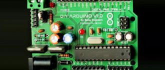
4Connecting a shift register to Arduino
Let's consider the practical application of the SPI interface. We will light the LEDs by controlling the 8-bit shift register via the SPI bus. a 74HC595 shift register to the Arduino . We will connect an LED with a nominal value of 220 Ohms to each of the 8 register outputs through a limiting resistor. The diagram is shown in the figure.
Wiring diagram for 74HC595 shift register to Arduino
Module power supply
Arduino Nano can work from different power sources, it can be connected either through a Mini-B USB computer, or from a regular unregulated 6-20 volts ( pin 30 ), or regulated 5 volts ( pin 27 ). The board will automatically select the highest voltage supply.
- Via mini-USB or microUSB when connected to a computer;
- Through an external power source, voltage 6-20V.
External power is stabilized thanks to LM1117IMPX-5.0 with a voltage of 5V. When connecting via USB, a Schottky diode is used.
5Sketch for controlling a shift register via the SPI interface
Let's write a sketch that implements a “traveling wave” by sequentially lighting the LEDs connected to the outputs of the shift register.
#include const int pinSelect = 8;
// register select pin void setup() {
SPI.begin();
// initializing the SPI interface pinMode(pinSelect, OUTPUT); // digitalWrite(pinSelect, LOW); // select slave devices (register) SPI.transfer(0); // clear the contents of the register digitalWrite(pinSelect, HIGH); // end of transmission Serial.begin(9600); } void loop() {
for (int i=0; i}
First, let's connect the SPI library and initialize the SPI interface. Let's define pin 8 as the SS slave selection pin. Let's clear the shift register by sending the value "0" to it. Initialize the serial port.
To light a specific LED using a shift register, you need to apply an 8-bit number to its input. For example, to make the first LED light up, we supply the binary number 00000001, for the second – 00000010, for the third – 00000100, etc. These binary numbers, when converted to the decimal number system, form the following sequence: 1, 2, 4, 8, 16, 32, 64, 128 and are powers of two from 0 to 7.
Accordingly, in the loop() , we recalculate from 0 to 7 based on the number of LEDs. The pow(base, power) raises 2 to the power of the loop counter. the round() function to convert the result to an integer . And we transfer the resulting number to the shift register. For clarity, the values obtained during this operation are displayed in the serial port monitor: the unit “runs” through the digits - the LEDs light up in a wave.
Numbers sent to the 74HC595 shift register
Timers (PWM)
Timer outputs: in the microcontroller, in addition to the regular computing core with which we work, there are also “hardware” counters that work in parallel with all the other hardware. These counters are also called timers, although they have nothing to do with timers: counters literally count the number of ticks made by the crystal oscillator, which sets the operating frequency for the entire system. Knowing the frequency of the oscillator (usually 16 MHz) you can determine time intervals with very high accuracy and do something based on this. What use are these meters to us? Out of the box, called Arduino IDE, we have several ready-made timer-based tools (time functions, delays, pulse length measurements, and others).
This article is about pins and outputs, so we’ll talk about them: each counter has two GPIO outputs. The nano (ATmega328p MK) has three counters, respectively, 6 outputs. One of the counters' capabilities is the generation of a PWM signal, which is output to the corresponding GPIOs. For nano these are D pins 5 and 6 (counter 0), 9 and 10 (timer 1) and 3 and 11 (timer 2). A separate lesson is devoted to the PWM signal, now let’s just remember that with its help you can control the brightness of LEDs, the rotation speed of motors, the heating power of the coils and much more. But you need to remember that the current limit of 40 mA has not gone away and nothing more powerful than LEDs cannot be powered from the pins.
6 “Traveling wave” of LEDs
The LEDs light up one by one, and we observe a running “wave” of lights. The LEDs are controlled using a shift register, to which we connected via the SPI interface. As a result, only 3 Arduino pins are used to control 8 LEDs. If we were connecting the LEDs directly to the Arduino's digital ports, we would need to use a separate port for each LED.
We studied the simplest example of Arduino working with the SPI bus. We will consider in more detail the operation of several shift registers with independent and cascaded connections in a separate article.
Choosing a board and port
Open Arduino IDE. From the Tools>Board menu, select Arduino/Genuino Mega or Mega 2560.
Select the processor/microcontroller of the board, usually ATmega2560. From the Tools>Processor menu, select ATmega2560 (Mega 2560).
Select the board's serial device from the Tools>Port menu. Most likely it is COM3 (Arduino/Genuino Mega or Mega 2560) or higher (COM1 and COM2 are usually reserved). To find out, you can unplug your board and reopen the menu; the entry that disappears must be Arduino or Genuino Mega. Connect the board and select this serial port.
If you have an Arduino Mega 2560 CH340G model, then it is better to use the Arduino as ISP programmer.
It is possible not to use a bootloader and program the microcontroller via ICSP pins (in-circuit programming).
Programming fuse bits on ATmega microcontrollers
Arduino ISP programmer
can be used to program the fuse bits of
ATmega
. Fuse bit programming allows you to configure onboard peripherals and microcontroller behavior. For example, you can set the clock frequency, program a watchdog timer, and much more. However, this requires experience and attention, because if you set the fuse bits incorrectly, the microcontroller will stop working, and it can be very difficult to restore it.
- Getting Started with the Arduino ISP // Retired
iOnline
In the last article about a review of the Chinese Arduino market, I wrote about the Chinese Arduino ProMini. The peculiarity of these boards is that they cannot be connected to a computer directly. To connect Arduino ProMini you must use a USB-TTL converter. Actually, my article is dedicated to these devices. As always, I only describe devices that I have personally purchased. This is not an advertisement. Just sharing information with the world about where you can buy them and which ones I used. This is not the ultimate truth, everyone can have their own opinion. Anyone interested, welcome to cat.
So. Today, the market for USB-TTL converters is very extensive. There are a lot of varieties of these same adapters. Their main task is to make friends between the microcontroller and the computer. The most common ones are USB-FTDI and USB-TTL. If we talk about the arduino platform, then sometimes there is a need for a USBASP / USBISP converter. By and large, USB-FTDI is the same USB-TTL; they are all simply built on the basis of different chips and, by and large, in most cases have the same functionality, which makes them the same for an ordinary radio amateur. Let's look at USB-TTL converters in more detail.
So. Today, in our and the Chinese market, USB-TTL converters are widely represented based on the following chips: MAX3232, FT232, CH340, CP2102. I had a chance to work with programmers on the last two chips. Programmers on the MAX chip did not interest me, because... came across only with a COM port for connecting to a PC, which significantly narrowed the range of computers to which it can be connected. I read not very good reviews about FT232 programmers, so I decided not to risk it. It’s not a fact that they are so bad, I just decided not to mess with them. In short, the next story will be about programmers based on CH340 and CP2102 chips.
Let's start with the programmer on the CH340 chip. The device is notable for the fact that this chip is used on Chinese clones of Arduino Nano, NodeMCU v3, Wemos D1 and others. Which allows us, in some way, to call it native to this platform. Although there are NodeMCU and Wemos with USB-TTL based on CP2102.
USB-TTL based on CH340
USB-TTL based on CH340
The photo shows programmers based on the CH340 chip manufactured by RobotDyn. This is a Russian company that develops devices, and the Chinese make them for them. By and large, normal high-quality adapters. The distinctive features of these samples include the ability to work with 3.3 and 5 Volt logic. The presence of an RST pin for connecting to the Arduino Promini to enter it into the firmware upload mode. This can be useful. You know, it’s not always possible to reboot the board at the right time for it to start working.
By default, there are no drivers in the operating system for this adapter. So you will need to additionally download and install them. In order not to force you to search for the necessary drivers, I have taken care of everything. Click “” and download the drivers from my GITHUB repository. The selection of drivers was made from the manufacturers' websites. In the selection of drivers for Windows, Linux, Mac OS.
To work with this module on Windows, you need to install drivers. The kit also includes drivers for MAC OS X. So, for some reason this converter worked on MAC OS without installing drivers at all. I just plugged it into my macbook and it worked. From which I conclude that driver installation is not always required on mac OS X. There is a chance that I installed the driver a long time ago and then forgot. So I recommend checking before you dance with a tambourine 
You can buy such adapters using the following links:
USB-TTL adapter based on CH340 from RobotDYN with regular USB USB-TTL adapter based on CH340 from RobotDYN with Micro USB
Now let's move on to adapters based on the CP2102 chip. My adapter looks like this:
USB-TTL based on CP2102
USB-TTL based on CP2102
This adapter has. I mean specifically my copy, and not all modules on such chips; there is no RST pin, with which you can automatically reboot the Arduinos. Otherwise, the layout is similar to the previous model. Well, in terms of functions, they are almost identical. Unless it's a Chinese noname. But nevertheless it works great and fulfills its functions. It's funny, I bought one such module to try, and then ordered a second one from the same store. So the first one came in heat shrink, and the second one did not. Along the way, the Chinese decided to save a little money.
Regarding drivers. I didn’t need them to work on OS Windows 10. The device was identified immediately. But again, maybe I accidentally installed them at some point. Here is the link “” they are also located in my GITHUB repository. If there were no problems with Windows, then problems arose with Mac OS X. No matter what I did, no matter what manuals I tried, the adapter was not identified. Just in case, the repository also contains drivers for mac os. Maybe they will be useful for you.
You can buy such adapters using the following links:
USB-TTL adapter based on CP2102 Store:GREAT WALL Electronics Co., Ltd. USB-TTL adapter based on CP2102 Store:WAVGAT Store
Above I provided information about the most common programmers. But there are also more specific models. Sometimes it happens that Arduinos break. For example, after an unsuccessful flashing, the bootloader is merged. What to do in this case? Or here's another problem for you. We have an Ender 3 3D printer, which needs to be loaded with firmware, however, the bootloader on its board is not flashed at all, what should we do in this case? Well, another option. You decided to explore new horizons and purchased a board based on the STM32F103C8T6 chip, you need to install the correct bootloader to work with the Arduino IDE. Conventional USB-TTL converters are not always suitable for such tasks. Then you have to resort to collective farming with an Arduino Uno, or get a normal programmer.
To solve such problems, I purchased 2 programmers:
Programmer ST-LINK
I purchased this programmer for flashing boards with STM32. so-called ST-Link
But I purchased this programmer for flashing bootloaders into Arduinos and 3D printer boards (for example, for Ender 3 firmware):
USB ASP programmer
The programmer came complete with a 10-pin cable, however, not all boards have 10-pin pins. In order not to worry, I additionally purchased an adapter:
As it turned out later, both of these programmers are interchangeable. And they are not just interchangeable, but can also be converted into each other. So, for the most part, one is enough. However, the firmware of these things is another story.
By the way, the use of these programmers allows you to flash firmware into Arduinos without a bootloader and work with microcontrollers at lower levels. Encrypt firmware, as well as install various types of protection, but this is already functionality for a guru.
I must warn you that these programmers also require drivers to work. .
Unfortunately, I have not yet gotten around to working with them seriously. But I decided to stock up on them in advance, so that if I suddenly need them, I’ll have them on hand. Because we can’t find such things here, and if you do find them, they won’t be cheap. Here are links to purchase these programmers at normal prices:
USBASP adapter Store:GREAT WALL Electronics Co., Ltd. USBASP adapter Store:WAVGAT Store Adapter for USBASP adapter Store:WAVGAT Store ST-Link adapter Store:GREAT WALL Electronics Co., Ltd. ST-Link adapter Store:WAVGAT Store
Well, now a few words about connecting USB-TTL converters based on CH340 and CP2102 chips. Let us connect the Arduino ProMini (with a voltage of 5 Volts) to the computer. To do this, you need to connect the Arduino as shown in the diagram:
Everything is simple with nutrition. + connect the programmer to the + arduino. – programmer (GND) connect to – arduino (GND). We connect the RX of the programmer to the TX of the arduino, and connect the TX of the programmer to the RX of the arduino. That's it, now you can connect the device to your computer and flash it.
I looked at the general connection diagram. Well, then go to the Arduino IDE and upload your sketch.
Clean code for you and stable operation of your hardware.