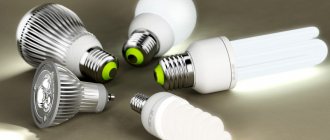
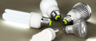
The design of an energy-saving lamp depends on the specific type of light source. In most cases, compact fluorescent lamps (CFLs) equipped with a threaded base and characterized by a power of 7 W and above are called energy-saving.
Their popularity compared to linear products is due to their compactness, the presence of a standard base (E27 or E14 for night lamps) and the absence of the need for ballasts (ballasts).
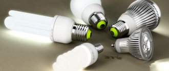
Types of energy saving lamps
There are several criteria by which energy-saving lamps are classified. The most common of them are base and glow temperature.
A socket is an element used to fix the product in a lighting fixture and supply electricity. Its main types are threaded and pin.
Most often in the domestic sphere, threaded sockets are used, screwed into ordinary cartridges. They are designated by the letter E and a numerical value indicating the diameter in millimeters. E27 is considered standard, while E14 is used in table lamps or sconces. And yet, threaded sockets are more often installed in DRL and sodium lamps intended for street lighting.
The pin type is used for specific luminaires. They are available with two or four pins, and the connectors themselves are marked with the letter G and a numerical value. Relevant for powerful lighting devices.
Depending on the glow temperature, an energy-saving lamp emits light of a certain shade (measured in Kelvin):
- Warm light (yellow) - 2700 K. The shade is similar to the glow of conventional (incandescent) lamps.
- Natural white light - 4200 K. Fluorescent lamps, neutral shade.
- Cold light (white) - 6400 K. Close to the blue spectrum, therefore it is characterized by a bluish tint. Typically used in industrial facilities in lamps of 65 W and above.
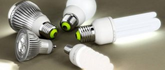
Energy-saving lamps also come in different shapes - tubular, spiral, arc-shaped. In the first case, there are no protective elements.
Main conclusions
Energy-saving lamps differ in the type of base (threaded and pin), in the color temperature of the light flux, as well as in the geometric parameters and shape of the bulb. At the same time, among its main operational characteristics the following stand out:
- Power.
- Type of base.
- Flask shape.
- Colorful temperature.
- Lifetime.
The operation of an energy-saving fluorescent lamp is based on a circuit for igniting the glow of mercury vapor under the influence of a high-voltage voltage passing through a filament coil. Its main features are durability, economy, uniform bright glow and the possibility of self-repair.
If you know another energy-saving lamp scheme or you just want to share useful information, be sure to write about it in the comments.
Operating principle and design of an energy-saving lamp
A CFL consists of a hollow glass bulb, the inside of which is filled with mercury vapor. When electric current is applied, an arc discharge is formed between the electrodes, connected to the starting capacitor. Due to this, ultraviolet radiation is formed, the spectrum of which is invisible to the human eye. To convert the glow into visible light, the inner walls are coated with a phosphor, guaranteeing a bright glow. If compared with an incandescent lamp of the same energy consumption, the luminous efficiency will be significantly higher. The cost of the device depends on what the phosphor consists of.
The disadvantage of energy-saving lamps is the fact that they cannot be directly connected to a 220 V power supply. The mercury vapor in them when turned off has a high resistance, so a pulse with a high voltage is needed to form a discharge. After the discharge is formed, the resistance becomes negative. If there are no protective elements in the circuit, this will lead to a short circuit. In tubular devices, an electromagnetic ballast is used, installed directly in the lamp.
Main performance characteristics
When choosing energy-saving fluorescent lamps, the following set of characteristics has a great influence on the scope of their further application:
- Power. Varies from 7 to 100 W and above. For domestic conditions, models up to 20 watts are sufficient (which is comparable in brightness to an incandescent lamp 5 times stronger!).
- Base modification. Selected based on the characteristics of the lamp.
- Flask geometry. It is taken into account according to the parameters of the lighting device and compliance with external conditions of use.
- Radiation temperature. Depends on the purpose of the illuminated objects.
- Lifetime. Varies from 5 to 12 thousand hours.
Components of the circuit
In addition to standard structural elements, such as a bulb and a base, an electronic circuit (electronic ballast - ballast) is hidden under the housing. Not every “housekeeper” has it (for example, it is absent in CFLs). Today, ballasts remain the most reliable product for the operation of fluorescent lamps, the quality of which determines their service life.
The electronic circuit consists of the following components:
- starting capacitor - generates a powerful impulse necessary to start the lamp;
- filters - needed to eliminate radio frequency interference and electromagnetic radiation that enter the circuit along with the current (reduce flicker);
- capacitive filter - an additional element that smoothes out the remaining ripples;
- current limiting choke - to protect the circuit from high current (maintains the current at a given level);
- bipolar transistors;
- driver - to limit current;
- fuse - prevents the lamp from failing, prevents the circuit from igniting during voltage surges.
History of creation
Officially, the first luminescent or, as it is also called, fluorescent lamp was created at the beginning of the last century by American engineer-inventor Peter Cooper Hewitt, who received a patent for it on September 17, 1901. Although some researchers dispute his primacy in the invention, calling the “father” of the fluorescent lamp the little-known German physicist Martin Arons, who experimented with mercury lamps at the end of the 19th century.
The fluorescent lamp invented and patented by Hewitt contained mercury, the vapor of which was heated by an electric current passed through it. The Hewitt lamp was spherical and slightly curved; it gave more light than the Lodygin-Edison lamps, but this light was bluish-green, unpleasant to the eye. For this reason, the first mercury lamps were used only by photographers and they were not widely used.
Peter Cooper Hewitt. 1861-1921
The fluorescent lamp in its almost modern form was created by a group of German inventors led by Edmund Germer, who patented their invention on December 10, 1926. It was Germer who came up with the idea of applying a fluorescent coating to the glass surface of the lamp from the inside, which converted the ultraviolet glow of a mercury lamp into white light that did not hurt the eyes. Albert Hull, an engineer, had developed a fluorescent lamp with a similar coating by early 1927, but the company was forced to acquire the patent from Edmund Germer, who had filed it earlier.
Since the acquisition of Germer's patent, General Electric engineers have actively begun to improve fluorescent lamps, trying to bring them to mass production. To reduce the size of the bulb, round and U-shaped lamps were created, demonstrated at the GE stand at the 1939 New York World's Fair; lamps with a compact spiral bulb were developed by General Electric engineer Edward Hammer in 1976. However, spiral-shaped fluorescent lamps were never put into production in the 80s, because company executives considered the costs of building new factories excessive. In 1995, Chinese manufacturers took advantage of the slowness of General Electric by launching the production of energy-saving lamps with spiral bulbs.
Edward Hammer with his invention - a lamp with a compact spiral bulb
The screw-in lamp with magnetic ballast (SL) was created in 1980 - it was the first fluorescent lamp of its kind to compete with incandescent lamps. An energy-saving lamp with an electronic ballast (CFL) was first demonstrated by the German concern Osram in 1985.
This is interesting: How much does a set of dishes for a dishwasher cost?
How does ignition occur?
The voltage falling across the dinistor leads to the formation of a pulse that enters the transistor and leads to the opening of the element. As soon as the start is completed, the circuit is blocked by the diode bridge. At the moment the transistor opens, the capacitor is charged, which prevents the dinistor from opening again.
The transistor acts on a transformer made of a ferrite ring with three windings in several rows. Voltage is applied to the filaments through a resonant circuit and a capacitor.
As soon as a glow appears in the tube, it is characterized by a resonant frequency determined by a capacitive capacitor. When igniting, the voltage reaches 600 V (at the moment of starting, the value is 4–5 times higher than the average), so it is necessary to monitor the integrity and tightness of the bulb. If this is ignored, the transistors will be damaged.
When the gas in the flask is completely ionized, the capacitor with the largest capacity is bypassed. The frequency decreases, control passes to the second capacitor. The voltage is reduced to a value sufficient to maintain the lamp glow. The cathode and anode are swapped, which ensures uninterrupted operation of the electronic circuit and simplifies repairs if necessary.
We calculate the capacity of the required voltage
To save money, capacitors with a small capacity are used. The ripple indicator of the incoming voltage will depend on them. To reduce ripple, it is necessary to increase the volume of capacitors; this is also done to increase the ripple rate only in the reverse order.
To reduce size and improve compactness, it is possible to use electrolyte capacitors. For example, you can use capacitors that are built into photographic equipment. They have a capacity of 100µF x 350V.
Twenty watt power supply
To provide a power supply with an indicator of twenty watts, it is enough to use a standard circuit from energy-saving lamps and without winding additional winding on the transformers. In the case where the choke has free space and can accommodate additional turns, you can add them.
Thus, you should add two to three dozen turns of the winding to be able to recharge small devices or use the UPS as an amplifier for equipment.
20 watt power supply circuit
If you need a more effective increase in power rating, you can use the simplest copper wire coated with varnish. It is specially designed for winding. Make sure the insulation on the standard inductor winding is good enough, as this part will be affected by the incoming current. You should also protect it from secondary turns using paper insulation.
The current power supply model is 20 watts.
For insulation we use special cardboard with a thickness of 0.05 millimeters or 0.1 millimeters. In the first case, two words are needed, in the second, one is enough. We use the maximum cross-section of the winding wire; the number of turns will be selected by trial. Usually quite few turns are needed.
Reducing the transverse diameter of the wire used will of course increase the number of turns, but this will only have a negative effect on the power.
100 watt power supply
To be able to increase the power of the power supply to hundreds of watts, it is necessary to additionally tighten the pulse transformer and expand the capacity of the filter capacitor to 100 farads.
100 watt power supply circuit
To lighten the load and reduce the temperature of the transistors, radiators should be added to them for cooling. With this design, the efficiency will be around ninety percent.
Transistor 13003 should be connected
A transistor 13003 should be connected to the electronic ballast of the power supply unit, which can be secured using a shaped spring. They are advantageous in that there is no need to install a gasket with them due to the absence of metal platforms. Of course, their heat transfer is much worse.
It is best to carry out fastenings using M2.5 screws, with pre-installed insulation. It is also possible to use thermal paste that does not transmit mains voltage.
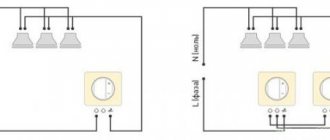
Connection to a 220 volt network
The connection is made using an incandescent lamp. It will serve as a protective mechanism and is connected in front of the power supply.
In this case, the lamp serves as a ballast, which has a non-linear indicator and perfectly protects the UPS from network malfunctions. The lamp power value must be selected in the same way as the power of the switching power supply itself.
Since it is possible that the power supply will transmit high voltage, make sure that all its connections and contacts are properly insulated. The same applies to all transistors; they should also be isolated from the external environment, because they can pass current through their housing.
How repairs are made
To find the cause of the malfunction, you should disassemble the lamp into its component parts. Detach the top and bottom parts and turn off the flask. Using an ohmmeter, check the filament coils on the bulb itself. If one of them burns out, repair the bulb. To complete the helix, use a 10 ohm high power resistor. In addition, remove the diode that shunts this spiral (if there is one in the circuit).
If a resistor burns out in lamps with a power exceeding 30 W (inclusive), there is a high probability of transistor failure, which is associated with a breakdown of the capacitor. To correct the situation, a new resistor is installed to act as a fuse, and the transistors are also replaced.
Modernization is also possible. Drill the holes necessary for ventilation in the base. Some models of energy-saving lamps are already produced with them, but there are unscrupulous manufacturers who do not think about cooling.
Important! Never use lamps with a drilled base in rooms with high humidity levels. This can lead to failure of the capacitor or the entire device.
Characteristic
Energy-saving lamps (ESL) are gradually becoming the main source of light both in the industrial sector and in everyday life. Their advantages are undeniable. Energy savings, high efficiency and light output, long service life and low heating make them one of the most promising electrical devices of the near future.
Scientists are conducting research to improve the quality of ESL. Positive results are not long in coming. However, some serious shortcomings of products have not yet been completely eliminated. There are many low-quality products on the markets that do not meet the requirements of energy saving and environmental safety. Products from iconic manufacturers are good in most respects, but have a high cost. In these conditions, repairing energy-saving lamps with your own hands remains relevant.
Making a UPS with your own hands
Most often, during the manufacture of a switching power supply, it is necessary to slightly change the structure of the inductor if a two-transistor circuit is used for this purpose. Of course, some elements in the device will need to be removed.
If a power supply is being manufactured that will have a power of 3.7-20 Watts, then the transformer is not the main component. Instead, it is best to make several turns of wire, which are attached to the magnetic circuit. To do this, it is not necessary to get rid of the old winding; they can be done on top.
It is recommended for this purpose to use MGTF brand wire with fluoroplastic insulation. A small amount will be needed. Despite this, the winding will be completely covered, since most of it is allocated to insulation. Because of this, such devices have low power ratings. To increase it, you need to use an AC transformer.
Using a transformer
The main advantage of making a power supply with your own hands is that it is possible to adapt to the performance of the transformer. In addition, there is no need for a feedback circuit, which is most often an integral part in the operation of the device. Even if some mistakes were made during assembly, most often such a block will work.
In order to make a transformer with your own hands, you will need to have a choke, inter-winding insulation, and a winding. The latter is best made from varnished copper wire. It should be remembered that the choke will operate under voltage.
The winding must be carefully insulated even when it has a factory-made special protective film made of synthetic material. As insulation, you can use either electrical cardboard or ordinary paper tape, the thickness of which should be at least 0.1 mm. Only after the insulation has been made can copper wire be wound over it.
As for the winding, it is best to choose the wire as thick as possible, but the number of required turns can be selected based on the required performance indicators of the future device.
Thus, it is possible to make a UPS that will have a power of more than 20 W.
Purpose of the rectifier
To prevent saturation of the magnetic circuit in the pulse unit, it is necessary to use only a full-wave output rectifier. In the event that the transformer must step down the voltage, it is recommended to use a zero-point circuit. To implement such a circuit, you need to have two absolutely identical secondary windings. You can make them yourself.
It should be taken into account that a diode bridge type rectifier is not suitable for this purpose. This is due to the fact that a significant amount of power will be lost during transmission, and the electrical voltage value will be minimal (less than 12V). But if you make a rectifier from special pulse diodes, then the cost of such a device will be much more expensive.
Setting up the device
After the power supply is assembled, you need to check its operation at maximum power. This is necessary in order to measure the heating temperature of the transformer and transistor, the values of which should not exceed 65 and 40 degrees, respectively. To avoid overheating of these elements, it is enough to increase the cross-section of the winding wire. It also often helps to change the power of the magnetic circuit upward (the ESR is taken into account). If the choke was taken from the ballast of an LED lamp, it will not be possible to increase the cross-section. The only option is to control the load on the device.
Application area
Fluorescent lamps with different types of bases:
- Lamps with a 2D base are used for decoration, sometimes used for built-in lighting of modern shower stalls.
- Sockets of types G23, 2G7 are applicable in wall lamps with special holes.
- Base type G24 is intended for use in industrial and household luminaires.
- G53 sockets are produced in a sealed housing and are intended for wet rooms, for installing suspended and plasterboard ceilings.
Sources equipped with E14, E27, E40 sockets are used in household sockets instead of incandescent lamps. This type of fluorescent light sources has large dimensions, therefore, replacement is not possible for all sizes of lamps.
Continuous spectrum sources produce light that has a beneficial effect on health. Unlike conventional linear spectrum light bulbs, they provide better color rendition.
Special colored sources are intended for general lighting, as well as:
- Having a colored phosphor - for lighting design (art lighting, city lights, inscriptions, signs).
- Possessing a pink phosphor, they are often used in the meat industry to give meat a marketable appearance.
- Ultraviolet light – suitable for lighting in darkened rooms, for disinfection (in medical institutions), and as decoration for entertainment venues.
LED light bulbs are used for household, industrial, and street lighting. LED sources have an emitter predominantly in one direction, allowing them to be used for directional and local lighting.
In addition to the above points, LED light bulbs are widely used for lighting museums and art galleries, since there is no ultraviolet component in the light spectrum.
The luminaires are used to control lighting in industrial and office premises, corridors, warehouses, public places, elevators, parking lots, etc.
What does a CFL consist of?
Energy saving lamp device
Modern energy-saving lamps consist of three main parts:
- flask - glass tube;
- a housing in which the electronic ballast is located;
- base
But the main details of an energy-saving lamp are only what is visible from the outside.
Inside the flask, sealed on both sides, there are electrodes to which electricity is directly supplied. The inside of the flask itself is coated with a special substance called phosphor. The cavity inside the glass tube is filled with an inert gas mixed with mercury vapor.
As for the electronic ballast, everything is much more sophisticated. An electronic ballast is a complex device that performs, in essence, the same role that the choke and starter performed in old fluorescent lamps, i.e., it controls the ignition and maintenance of the glow in the bulb.
The sockets of energy-saving lamps can be different. The most common, of course, is E27. It is identical to the base of a conventional incandescent lamp. In general, the marking “E” means that it is threaded, and the number following it is its diameter in millimeters. Also, compact energy-saving lamps can have E14 (14 mm) and E40 (40 mm) sockets.
Another marking - G - indicates that the base is two-pin, and the number that follows the letter designation indicates the size between the pins.
Drastic changes
Ideally, for the secondary winding you need to use the same type of wire as in the original factory version. But often the “window” of the choke magnetic receiver is so narrow that it is not possible to even wind one full layer. And it is also necessary to take into account the thickness of the gasket between the primary and secondary windings. As a result, it will not be possible to radically change the power output by the lamp circuit without making changes to the composition of the board components. In addition, no matter how carefully you carry out the winding, you will still not be able to make it as high quality as in factory-produced models. And in this case, it is easier to assemble a pulse unit from scratch than to remake the “good” obtained for free from a light bulb. Therefore, it is more rational to look for a ready-made transformer with the required parameters at the disassembly of old computer or television and radio equipment. It looks much more compact than a “homemade” one. And its safety margin cannot be compared.
Transformer
And you won’t have to rack your brains over calculating the number of turns to obtain the desired power. Soldered to the circuit - and you're done! Therefore, if you need more power from the power supply, say about 100 W, then you will have to act radically. And only the spare parts available in the lamps cannot be used here. So, if you want to further increase the power of the power supply, you need to unsolder and remove the original inductor from the light bulb board (indicated in the diagram below as L5).
Detailed UPS diagram
Connected transformer
Then, in the section between the previous location of the choke and the reactive midpoint (in the diagram, this section is located between separating capacitors C4 and C6), a new powerful transformer is connected (indicated as TV2). If necessary, an output rectifier is connected to it, consisting of a pair of connecting diodes (they are designated in the diagram as VD14 and VD15). It wouldn’t hurt to simultaneously replace the diodes on the input rectifier with more powerful ones (in the diagram these are VD1-VD4). Don't forget to also install a larger capacitor (shown in the diagram as C0). It must be selected at the rate of 1 microfarad per 1 W of output power. In our case, a 100 mF capacitor was taken. As a result, we get a fully capable switching power supply from an energy-saving lamp. The assembled circuit will look something like this.
We identify faulty elements on the ballast board.
Fuse.
First of all, we check the fuse. It's easy to find. One end of it is soldered to the central contact of the lamp base, and the other to the board. A tube made of insulating material is put on it. Typically, fuses do not survive such a malfunction.
But as it turned out, this is not a fuse, but a half-watt resistor with a resistance of about 10 ohms
, and was burnt out (in a cliff).
The serviceability of the resistor is easily determined. Place the multimeter in resistance measurement mode to the “ continuity
"or "
200
" and take the measurement.
If the fuse resistor is intact, then the device will show a resistance of about 10 ohms
, but if it shows
infinity
(one), then it is broken. You can read how to measure resistance here.
Here, place one multimeter probe to the central contact of the base, and the second to the place on the board where the lead of the fuse resistor is soldered.
One more thing. If the fuse resistor turns out to be burnt out, then when you bite it, try to bite it closer to the resistor body, as shown on the right side of the top picture. Then we will solder a new resistor to the terminal remaining in the base.
Bulb (lamp).
Next, check the resistance of the bulb filaments. It is advisable to unsolder one pin on each side. The resistance of the threads should be the same, and if it is different, it means one of them has burned out. Which is not very good.
In such cases, experts advise soldering a resistor parallel to the burnt spiral with the same resistance as that of the second spiral. But in my case, both spirals turned out to be intact, and their resistance was 11 Ohms
.
The next step is to check all semiconductors for serviceability - these are transistors
,
diodes
and
zener diode
. If you don’t know how to test a transistor or diode, then read the article on how to test a transistor with a multimeter.
As a rule, semiconductors do not like working with overloads and short circuits, so we check them carefully.
Diodes and zener diode.
There is no need to unsolder the diodes and zener diode; they already connect perfectly right on the board. The direct resistance of the pn junction of the diodes will be within 750 Ohms
, and the inverse must be
infinity
. All my diodes turned out to be intact, which made me a little happy.
Double-anode zener diode
, therefore, in both directions it should show a resistance equal to
infinity
(one).
If some of your diodes turn out to be faulty, then you need to purchase them at a radio components store. 1N4007 are used here
. But I couldn’t determine the value of the zener diode, but I think that you can install any one with a suitable stabilization voltage.
Transistors.
The transistors, and there are two of them, will have to be unsoldered, since their base-emitter pn junctions are shunted by the low-resistance winding of the transformer.
One transistor rang both right and left, but the second was supposedly intact, but between the collector and emitter, in one direction, showed a resistance of about 745 Ohms
. But I didn’t attach any importance to this, and considered it faulty, since this was the first time I was dealing with transistors of type 13003.
I couldn’t find transistors of this type in a TO-92 package, so I had to buy a larger one in a TO-126 package.
Resistors and capacitors.
They also need to be checked for serviceability. But what if.
I still had one SMD resistor, the value of which was not visible, especially since I did not know the circuit diagram of this ballast. But there was another similar working energy-saving lamp, and it came to my rescue. It shows that the value of resistor R6
is
1.5 Ohm
.
To finally make sure that all possible faults were found, I rang all the elements on the working board and compared their resistance on the faulty one. And he didn’t solder anything.
1. Transistors 13003 – 2 pcs. 10 rubles each (in the TO-126 case - I took 10 pieces); 2. SMD resistors - 1.5 Ohm and 510 kOhm, 1 ruble each (I took 10 pieces); 3. 10 Ohm resistor – 3 rubles per piece (I took 10 pieces); 4. Diodes 1N4007 – 5 rubles per piece (I took 10 pieces just in case); 5. Heat shrinkage – 15 rubles.
What is the essence of ballast reconstruction?
To be able to connect the load to a separate winding, you must either wind it on inductor L5, or use an additional transformer. Converting ballast into a UPS involves:
- dismantling the CFL ballast housing. This can be done with a screwdriver, which must be inserted one by one, step by step, along the line of contact of its parts. The force applied to the lamp should not be excessive for the bulb. We must try to press on it with minimal force.
- Disconnecting the lamp contacts from the ballast board. To do this, their cores are unwound from the four pins on the board.
- Removing the board and connecting all four pins with jumpers (lamp bypass).
The ballast board has been removed from the lamp.
To further convert the electronic ballast into a power supply from an energy-saving lamp, you need to make a decision regarding the transformer:
- use the existing throttle by modifying it;
- or use a new transformer.