Electromagnetic starters PML
TU3420-091-05758109-2016. Electromagnetic starters of the PML series (hereinafter referred to as “starters”) are intended for use as switching
devices in electric drive control circuits, mainly in stationary installations, for remote starting by direct connection to the network, stopping and reversing three-phase asynchronous electric motors with a squirrel-cage rotor at voltages up to 660 V AC with a frequency of 50 and 60 Hz. The starters are equipped with thermal relays of the RTL TU3425-041 -05758109-2008 series, which provides protection of controlled electric motors from overloads of unacceptable duration and from currents arising when one of the phases is broken.
Optimal operating conditions, absence of noise and increased operational reliability are ensured by the use of special manufacturing technology for the magnetic contactor system. Wide possibilities for the layout of panels due to the possibility of mounting devices both vertically and turning to the right/left by 20°. Possibility of operation in harsh Russian conditions at ambient temperatures from -40°C to +55°C. Possibility of use in various operating conditions due to the enclosure with degree of protection IP54.
Symbol structure
Starter PML-Х1Х2Х3Х4Д-Х5А-Х6АС-(Х7А)-УХЛ3-Б-КЭАЗ
| Actuator | — Product group | |
| PML | — Series | |
| X1 | - A number indicating the size of the starter depending on the rated current: 1 - 10 A and 16 A, 2 - 25 A and 32 A, 3 - 40 A, 4 - 63 A, 5 - 100 A | |
| X2 | — A number indicating the intended use: 2 — irreversible | |
| X3 | — A number indicating the design according to the degree of protection: 2 — IP54 with “Start” and “Stop” buttons | |
| X4 | — A number indicating the number and design of auxiliary circuit contacts: | 40, 63, 100 |
| 0 | 1 "z" | 1 "z" + 1 "r" |
| 1 | 1 "r" |
An example of writing the designation of a starter with a rated current of 10 A, wear resistance version B, irreversible, degree of protection IP54, with 1 “z” auxiliary contact, with a switching coil for voltage 220 V with a frequency of 50 Hz, with a relay current setting range (7-10 A ) when ordering it and in the documentation of another product: Starter PML-1220-10A-220AS-(7-10 A)-UHL3-B-KEAZ
Starter PML-Х1Х2Х3Х4Д-Х5А-Х6АС-(Х7А)-УХЛ2-Б-КЭАЗ
| Actuator | — Product group | |
| PML | — Series | |
| X1 | - A number indicating the size of the starter depending on the rated current: 1 - 10 A and 16 A, 2 - 25 A, 3 - 40 A, 4 - 63 A | |
| X2 | — A number indicating the intended design: 2 — non-reversible, 6 — reversible with electrical and mechanical interlocking, 7 — star-delta | |
| X3 | — Execution by the presence of buttons: 1 — with a “Relay” button, 2 — with “Start” and “Stop” buttons, 3 — with “Start” “Stop” buttons and a signal lamp (manufactured only for voltages 127, 220 and 380 V , 50 Hz) | |
| X4 | — Design according to the number and purpose of auxiliary circuit contacts: | 40, 63 |
| 0 | 1 "z" | 1 "z" + 1 "r" |
| 1 | 1 "z" + 2 "r" |
An example of writing the designation of a starter for a rated current of 10 A, wear resistance version B, irreversible, degree of protection IP54, with “Start”, “Stop” buttons and a signal lamp, with 1 “z” auxiliary contact, with a switching coil for a voltage of 220 V frequency 50 Hz, with the relay current setting range (7-10 A) when ordering it and in the documentation of another product: Starter PML-1230-10A-220AS-(7-10a)-UHL2-B-KEAZ
Assortment of PML starters
Accessories for PML contactors and starters
Specifications
| Parameter name | Parameter designation | |||||
| Series | PML-1210 PML-1230 | PML-1611 PML-1621 PML-1631 | PML-1210D PML-1230D | PML-1611D PML-1621D PML-1631D | PML-2210 PML-2230 | PML-2611 PML-2621 PML-2631 |
| Type of main circuit current | variable | |||||
| Rated current, A | 10 | 16 | 25 | |||
| Motor power (AC-3) at 380 V 50 Hz, kW | 4,0 | 7,5 | 11 | |||
| Auxiliary contacts “z” - normally open “r” - normally open | 1 "z" | 1 "z" + 2 "r" | 1 "z" | 1 "z" + 2 "r" | 1 "z" | 1 "z" + 2 "r" |
| Execution | irreversible | reverse | irreversible | reverse | irreversible | reverse |
| Type of climate control | UHL2 | |||||
| Degree of protection | IP54 | |||||
| Design for switching wear resistance, million cycles (AS-3) | B-1.5 | B-1.0 | ||||
| Design for mechanical wear resistance, million cycles | B-10 | |||||
| Maximum switching frequency without load/with load, switchings per hour (AC-3) | 3600/2400 | 3600/1200 | ||||
| Rated operating current, A (AC-3) up to 380 V | 10 | 16 | 23 | |||
| Rated operating current, A (AC-3) at 660 V | 5 | 10 | 15 | |||
| Rated operating current, A (AS-1) | 20 | 32 | 40 | |||
| Rated operating current, A (AC-4) up to 380 V | 3,5 | 7,7 | 8,5 | |||
| Rated operating current, A (AC-4) at 660 V | 1,5 | 3,8 | 4,4 | |||
| Rated voltage of the main circuit, V | up to 660 | |||||
| Type of control circuit current | variable | |||||
| Rated control circuit voltage, V | 24, 36, 42, 48, 110, 120, 127*, 220*, 240, 380*, 400, 415, 440, 480, 660 | |||||
| Coil power consumption | ||||||
| switching on, VA | 70 | 110 | ||||
| retention, VA | 8 | 11 | ||||
| Rated insulation voltage, V | 660 | |||||
| Dimensions | ||||||
| Dimensions (HxWxD), mm | 160x87x116.5 | 280x123x143 | 185x101x134 | 280x123x143 | 185x101x134 | 280x123x143 |
| Installation, mm | 140 (2 M5 screws) | 260 (2 M5 screws) | 165 (2 M5 screws) | 260 (2 M5 screws) | 165 (2 M5 screws) | 260 (2 M5 screws) |
| Weight no more than, kg | 1,04 | 2,15 | 1,2 | 2,7 | 1,2 | 2,7 |
| 1,13 | 2,23 | 1,29 | 2,77 | 1,29 | 2,77 | |
| 2,27 | 2,85 | 2,85 | ||||
* Rated control circuit voltage for starters PML-1230, PML-1631, PML-1230D, PML-1631D, PML-2230, PML-2631
| Parameter name | Parameter designation | |||||
| Series | PML-3210 PML-3230 | PML-3210D PML-3220D PML-3230D | PML-3611D PML-3621D PML-3631D | PML-3610 PML-3620 PML-3630 | PML-4210 PML-4230 | PML-4610 PML-4620 PML-4630 |
| Type of main circuit current | variable | |||||
| Rated current, A | 40 | 63 | ||||
| Motor power (AC-3) at 380 V 50 Hz, kW | 18,5 | 30 | ||||
| Auxiliary contacts “z” - normally open “r” - normally open | 1 "z" + 1 "r" | 1 "z" | 1 "z" + 2 "r" | 1 "z" | 1 "z" + 1 "r" | 1 "z" |
| Execution | irreversible | reverse | irreversible | reverse | ||
| Type of climate control | UHL2 | |||||
| Degree of protection | IP54 | |||||
| Design for switching wear resistance, million cycles (AS-3) | B-1.0 | |||||
| Design according to M0V3U М U0, 1ГГ\1Л mechanical wear resistance, million cycles | B-10 | |||||
| Maximum switching frequency without load/with load, switchings per hour (AC-3) | 3600/1200 | |||||
| Rated operating current, A (AC-3) up to 380 V | 34 | 53 | ||||
| Rated operating current, A (AC-3) at 660 V | 21 | 43 | ||||
| Rated operating current, A (AS-1) | 60 | 80 | ||||
| Rated operating current, A (AC-4) up to 380 V | 18,5 | 28 | ||||
| Rated operating current, A (AC-4) at 660 V | 9 | 14 | ||||
| Rated voltage of the main circuit, V | up to 660 | |||||
| Type of control circuit current | variable | |||||
| Rated control circuit voltage, V | 24, 36, 42, 48, 110, 120, 127*, 220*, 240, 380*, 400, 415, 440, 480, 660 | |||||
| Coil power consumption | ||||||
| switching on, VA | 200 | |||||
| retention, VA | 20 | |||||
| Rated insulation voltage, V | 660 | |||||
| Dimensions | ||||||
| Dimensions (HxWxD), mm | 280x164x166 | 280x164x170 | 280x164x166 | 258x175x309 | 280x164x166 | 258x175x309 |
| Installation, mm | 260 (2 M5 screws) | 165x165 (4 M6 screws) | 260 (2 M5 screws) | 165x165 (4 M6 screws) | ||
| Weight no more than, kg | 3,1 | 2,4 | 3,24 | 6 | 3,11 | 6 |
| 3,15 | 2,42 | 3,24 | 6,08 | 3,16 | 6,08 | |
| 2,44 | 3,3 | 6,12 | 6,12 | |||
* Rated control circuit voltage for starters PML-3230, PML-3230D, PML-3630, PML-3631D, PML-4230, PML-4630
| Parameter name | Parameter designation | ||||||
| Series | PML-1220 | PML-1220D | PML-2220 | PML-2220D | PML-3220 | PML-4220 | PML-5220D |
| Type of main circuit current | variable | ||||||
| Rated current, A | 10 | 16 | 25 | 32 | 40 | 63 | 100 |
| Motor power (AC-3) at 380 V 50 Hz, kW | 4,0 | 7,5 | 11 | 15 | 18,5 | 30 | 45 |
| Auxiliary contacts “z” - normally open “r” - normally open | 1 "z" | 1 "z" + 1 "r" | |||||
| Execution | irreversible | ||||||
| Type of climate control | UHL3 | ||||||
| Degree of protection | IP54 | ||||||
| Execution according to switching HJnULUL 1 UHKUL. 1 Vlf NJIH CYCLIV (AC-3) | B-1.5 | B-1.0 | |||||
| MlPG|P1-1(=>1-1ы(=>PG1 V \\L IKJJ 1PSPIS 1 l\J mechanical wear resistance, million cycles | B-10 | B-5 | |||||
| Maximum switching frequency without load/with load, switchings per hour (AC-3) | 3600/2400 | 3600/1200 | 3600/750 | ||||
| Rated operating current, A (AC-3) up to 380 V | 10 | 16 | 23 | 28 | 34 | 53 | 86 |
| Rated operating current, A (AC-3) at 660 V | 5 | 10 | 15 | 18 | 21 | 43 | 56 |
| Rated operating current, A (AS-1) | 20 | 32 | 40 | 50 | 60 | 80 | 120 |
| Rated operating current, A (AC-4) up to 380 V | 3,5 | 7,7 | 8,5 | 12 | 18,5 | 28 | 44 |
| Rated operating current, A (AC-4) at 660 V | 1,5 | 3,8 | 4,4 | 7,5 | 9 | 14 | 21,3 |
| Rated voltage of the main circuit, V | up to 660 | ||||||
| Type of control circuit current | Variable | ||||||
| Rated control circuit voltage, V | 24, 36, 42, 48, 110, 120, 127, 220, 240, 380, 400, 415, 440, 480, 660 | ||||||
| Coil power consumption | |||||||
| switching on, VA | 70 | 110 | 200 | ||||
| retention, VA | 8 | 11 | 20 | ||||
| Rated insulation voltage, V | 660 | ||||||
| Dimensions | |||||||
| Dimensions (HxWxD), mm | 166x88x140 | 185x101x142 | 312x180x181 | ||||
| Installation, mm | 150 (2 M5 screws) | 165 (2 M5 screws) | 200x105 (4 M6 screws) | ||||
| Weight no more than, kg | 1,3 | 1,5 | 1,6 | 2,4 | 3,2 | 4,2 | |
Overall and installation dimensions of PML starters of climatic version UHL3
Starters PML-1220, PML-1220D for rated currents of 10 and 16 A in a plastic shell
Starters PML-2220, PML-2220D for rated currents of 25 and 32 A in a plastic shell
Starters PML-3220, PML-4220, PML-5220D for rated currents of 40, 63 and 100 A in a metal shell
Overall and installation dimensions of climate control starters UHL2
Irreversible starters 1 and 2 sizes in a plastic shell
| Starter type | A | A1 | IN | L | H | H1 | H2 | Screw for fastening | Weight, kg |
| PML-1210 | 140 ± 0,4 | 46 ± 0,3 | 87 ± 1 | 160 ± 1 | 116,5 ± 1 | 18 ± 0,3 | M5 - 6g 2 screws | 1,04 | |
| PML-1220 | 1,04 | ||||||||
| PML-1230 | 124,5 ± 1 | 1,13 | |||||||
| PML-1210D | 165 ± 0,4 | 52 ± 0,3 | 101 ± 1 | 185 ± 1 | 134 ± 1 | 19 ± 0,3 | 1,20 | ||
| PML-1220D | 1,20 | ||||||||
| PML-1230D | 142 ± 1 | 1,29 | |||||||
| PML-2210 | 1,20 | ||||||||
| PML-2220 | 1,20 | ||||||||
| PML-2230 | 142 ± 1 | 1,29 |
Reversing starters 1 and 2 sizes in a plastic shell
| Starter type | A | A1 | B | B1 | H | H1 | H2 | Screw for fastening | Weight, kg |
| PML-1611 | 260 ± 0,7 | 46 ± 0,3 | 123± 1 | 280±1 | 130,5±1 | 18 ± 0,3 | M5 - 6g 2 screws | 2,15 | |
| PML-1621 | 2,23 | ||||||||
| PML-1631 | 136,5 ± 1 | 2,27 | |||||||
| PML-1611D | 52 ± 0,3 | 143±1 | 19 ± 0,3 | 2,70 | |||||
| PML-1621D | 2,77 | ||||||||
| PML-1631D | 149 ± 1 | 2,85 | |||||||
| PML-2611 | 149 ± 1 | 2,70 | |||||||
| PML-1621 | 2,77 | ||||||||
| PML-1631 | 2,85 |
Irreversible starters of 3 and 4 sizes in a shell, reversible starters of 3 sizes with reduced weight and dimensions in a plastic shell
| Starter type | A | A1 | IN | B1 | H | H1 | H2 | Screw for fastening | Weight, kg |
| PML-3210 | 34,5±0,5 | 60,5±0,5 | 31 ± 0,5 | 59 ± 0,5 | M5 - 6g 2 screws | 3,100 | |||
| PML-3220 | 3,130 | ||||||||
| PML-3230 | 170,5 ± 1 | 3,156 | |||||||
| PML-3210D | 2,400 | ||||||||
| PML-3220D | 2,420 | ||||||||
| PML-3230D | 170,5 ± 1 | 2,440 | |||||||
| PML-3611D | 3,200 | ||||||||
| PML-3621D | 3,240 | ||||||||
| PML-3631D | 170,5 ± 1 | 3,300 | |||||||
| PML-4210 | 42 ± 0,5 | 42 ± 0,5 | 44 ± 0,5 | 3,110 | |||||
| PML-4220 | 3,140 | ||||||||
| PML-4230 | 170,5 ± 1 | 3,160 | |||||||
| PML-1720 | 54 ± 0,5 | 30 ± 0,5 | 54 ± 0,5 | 54 ± 0,5 | 26 ± 0,5 | 56 ± 0,5 | 3,300 | ||
| PML-1720D | 3,300 |
Reversible starters 3 and 4 sizes in a metal shell
| Starter type | Screw for fastening | Weight, kg |
| PML-3610 | M5 - 6g 4 screws | 6,00 |
| PML-3620 | 6,08 | |
| PML-3630 | 6,12 | |
| PML-4610 | 6,00 | |
| PML-4620 | 6,08 | |
| PML-4630 | 6,12 |
Catalog PML starters (.pdf, 2.53 MB)
Operating manual for electromagnetic starters of the PML series (.pdf, 1.24MB)
Operating principle
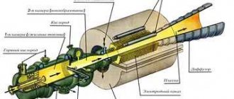
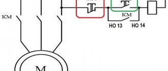
This multi-contact electromagnetic relay works as follows:
- Using a button, an electric current with a specified voltage is supplied to the control coil;
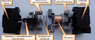
- The current passing through the turns of the coil leads to magnetization of the W-shaped fixed core of the base;
- The magnetized lower fixed core attracts the magnetic circuit located on the movable cross-arm, compressing the elastic return spring;
- As a result of the attraction of the traverse core to the base magnetic circuit, it is closed by the spring-loaded fixed power contacts;
- As a result of the pairwise closure of the movable contacts of the traverse of the fixed power contacts, the load is switched on.
Magnetic starter
Disconnection of the starter and, accordingly, the load connected to it occurs when the supply of electric current to the control coil is stopped: the lower core is demagnetized and ceases to attract the upper one, as a result of which the traverse with contacts under the action of an expanding elastic spring disconnects the power contacts.
On a note. Under normal conditions, a working starter makes clicking sounds of the same duration when turned on and off. If the device makes different sounds, then there may be various malfunctions of its internal components.
Additional blocks – PKL contact attachments
To obtain expanded capabilities of PKL contactors and PML magnetic starters used in electrical circuits, if it is necessary to increase the number of switched elements in certain systems, additional PKL contact blocks are used. They are available in five different versions in the first and second dimensions, which differ in the number of spring-loaded contacts in the form of bridges. The first dimension corresponds to two such groups of contacts, and the second – four groups of contacts.
Additional blocks for controlling their contacts must be inserted into the guides located in the head part of the PML starter. In this case, the protruding traverse from the contactor engages with the contacts of the block. The wires are connected to the blocks using screw terminals. The units can be operated at an alternating voltage of 660 V, as well as at a direct voltage with a maximum value of 400 V, providing up to 1,600,000 operations.
terms of Use
The electromagnetic starter is designed to operate at a temperature of +/-40 degrees Celsius, with a degree of environmental pollution of 3 points and at an altitude of no more than 2 thousand meters. Its normal operating position is to be mounted on a vertical plane using the terminals of the switching coil up and down with screws or by snapping a standard rail. Deviation from the top in any direction is acceptable.
Mandatory use with voltage limiter
The device may only be used in accordance with the instructions. Only in this case is it possible to achieve a positive effect from interacting with it and at the same time maintain its performance while protecting the controlled electric motor from overload and electric current that appears at the moment of a break in one phase.
You might be interested in: Installation of an electric meter
Use according to instructions
Rules of care
In order to maintain a magnetic starter in appropriate conditions, you need to be well aware of all the faults that such a unit most often encounters. This concerns a sharp increase in the temperature of parts and strong humming of the equipment.
Overheating is mainly associated with inter-turn short circuits of the coil, and in this case it is impossible to do without replacing it. Heating of parts can occur due to increased voltage in the electrical network.
A strong hum from the unit is observed in many cases. Among the main reasons is poor fit of the armature to the core due to contamination or damage to their surface. Other factors include jamming of the moving part and a decrease in the rated voltage in the network (by 15% or more).
Negative consequences can only be avoided with timely care. The huge advantage is that such a unit does not require expensive maintenance. The technician just needs to prevent dirt, dust and moisture from getting into the device. The tightness of the clamps and the condition of the contacts must be checked regularly. In addition, you can resort to a certain list of measures often used by electrical engineers.
What are these switches for and where are they used?
The domestic industry produces a large number of different contactors and magnetic starters.
Basically, they are combined into series according to certain common characteristics. One of these PML series combines small-sized switching devices. They operate in the current range of 9 - 95 A and are intended for widespread use in industry in networks with voltages up to 400 V industrial frequency. They should mainly be used to control asynchronous motors (modes corresponding to category AC-3), in electrical circuits with incandescent lamps and other lighting systems that use ballasts to control lamps, for switching circuits with electric heaters, as well as for switching inductive loads in modes , corresponding to category AC-1. The contactors, which can be installed on 35 and 72 mm rails using a securely attached steel base, correspond to dimensions 3 - 5. Their operating current load depends on the altitude above sea level and should be reduced by ten percent when placed above 2 km. With a warranty period of three years, contactors can last fifteen years or longer.
Options
The main parameters of such devices include:
- Switching wear resistance is a characteristic indicating the maximum number of on/off cycles the device can withstand without repairing or replacing contacts;
- Number and type of contacts;
- Rated current for which the device contacts are designed;
- Voltage supplied to the control coil;
- Degree of protection (IP) from moisture and dust;
- Availability of control buttons, signal lamp;
- Availability of reverse function and built-in thermal relay;
- Dimensions and weight;
- Type of fastening (on DIN rail, using screws or bolts).
On a note. The main characteristics of the starter can be found by deciphering its markings.
Functionality
Below are typical functions performed by magnetic starters, which are far from exhaustive of their applications:
- Control of asynchronous electric motors in drives of industrial mechanisms.
- Turning on external (street) city lighting, external and internal lighting of industrial facilities.
- Switching of electric heating devices (heating elements or infrared heaters) of electric heating systems.
- Use as triggers in industrial automation circuits.
The choice of magnetic starters is made when designing control and automation circuits, or during their repair, when to replace an outdated or missing device it is necessary to select its analogue.
