Software method
To eliminate bounce, various computers use software signal processing. In this case, for clocking, the signal is taken not directly from the contact, but a one-bit Boolean variable associated with it, generated by a special program:
- by temporarily delaying the signal for the period of possible contact chatter;
- by repeatedly reading the state of contacts at a given time interval. The program considers the circuit closed if during this period of time there is a period of stable contact closure;
- using a counting algorithm that takes into account the number of coinciding values of the closure signals in a certain period of time (ranging from 10 to 100 μs). If the program notices a specified number of closed state matches, it will consider the contact to be permanently closed and pass the signal.
The signal received by software is quite reliable and stable. The disadvantages of this debounce suppression scheme include only a small signal delay, which does not exceed 0.1 s. This time period is so small that it can be neglected in many cases. Typically, a person's finger lingers on the key until the button is released for more than 0.2 s.
Programmed devices receive control signals from buttons and transmit ideal pulses to consumer devices running on digital chips. As a result of the program cutting off bounce signals, only high-quality pulses are received at the inputs of the microcircuit. This ensures stable operation of digital devices and resists false triggering of logical decoders, regardless of the signal level and its quality.
Programmable debounce device
Water meter circuit on ESP8266 (Wemos D1 mini)
Diagram and example of a printed circuit board in the EasyEDA project. I left the I2C inputs unoccupied to connect the indicator.
Water meter circuit on Wemos D1 mini (ESP8266) with hardware elimination of contact bounce on the Schmitt trigger
I made the diagram on Wemos breadboard.
Water meter shield circuit board on Wemos D1 mini (ESP8266) with hardware contact debouncing on the Schmitt trigger
An example of a printed circuit board generated by autorouting in EasyEDA.
Printed circuit board shield of a water meter on Wemos D1 mini (ESP8266) with hardware de-bouncing of contacts on a Schmitt trigger
Ways to eliminate the unwanted effects of chatter
It is fundamentally impossible to eliminate or reduce chatter without changing the mechanical design of the contact system. Some types of contact systems, for example, the slider type, have virtually no chatter.
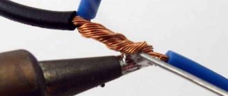
Another constructive way to eliminate chatter in low-current electromechanical switches is the use of contact pairs moistened with mercury. In these keys, the electrical circuit does not break when the contacts “bounce” during chattering, since when the solid contacts are mechanically opened, liquid mercury bridges are formed between them.
In power switches and relays, spark-extinguishing chains are often used to reduce switching wear of contacts.
When controlling inputs of digital devices that are critical to bouncing, special electronic circuits are used, for example with a trigger in the figure or another type: the signal from the contact is supplied through a low-pass filter in the simplest case - an RC circuit to an electronic circuit with a static transfer characteristic that has a hysteresis loop, for example, a Schmitt trigger, and the output of this device is used to clock a digital device.
In computing, for example, microprocessor systems, contact bounce suppression is usually carried out using software. In this case, not the signal from the bouncing contact itself is used as a timing signal, but some specially generated one-bit Boolean variable associated with it.
When programmatically generating a debounced contact signal, three of them are most widely used:
- Using the method of calculating the time of a steady state, the program repeatedly reads the state of the contact within a given time. If during a given time no change in state to the opposite is detected, then the contact is considered stably closed. Otherwise, if a change in state is detected within a specified time, the timing is interrupted or continues, but with a flag set or the number of state changes counted to evaluate the physical state of the mechanical contacts and the contact is considered open or in an unstable state if such information is used in the program .
- By counting the number of matching closed signal values, the program repeatedly reads the state of the contact, and if a certain number of closed confirmations have occurred within a given period of time, determined experimentally and selected in the range from 10 to 100, the contact is considered stably closed.
- By setting a time delay, the program, having detected a closed state of the contact, ignores its state for a time obviously longer than the duration of the bounce, and after this time checks the state of the contact again. If after this time the contact state is closed, then the corresponding variable changes value.
Motor control circuit
I was prompted to this publication by a long-standing problem that has been mothballed for me for more than six years and is associated with the stability of the operation of thermostats for incubators, mainly household and farm ones with a capacity of up to eggs. Initially, I did not immediately truncate it during laboratory tests; it surfaced only during operation at a real object. I temporarily avoided this problem by using microcontrollers with specially written programs that mitigated the problem. But a lot of customers wanted a cheaper and simpler thermostat, and I had to return to analog thermostats. This year I conducted a number of tests and experiments, the results of which formed the basis of a kind of report on the work done. Judge for yourself what came of it. Rattling in the switching of the incubator heater The whole fuss caught fire 6 years ago for one banal reason.
Via began to increasingly displace TTL microcircuits, leaving circuit technology behind them... In circuit methods for combating contact bounce, the use of a clock signal code at the output is detected by a comparator and clock.
What is chatter and where does it come from?
Any mechanical contact is not ideal. The surface of the contacts may be covered with a film of oxides or contaminants (not visible to the eye). The contacts are elastic and at the moment of contact they spring and bounce off each other several times until they finally touch. This is not all, but perhaps the main causes of rattling.
I will illustrate the manifestation of contact bounce with the following, very simple example of pressing and releasing a button
Here Sw is a button. It is clearly visible that contact bounce appears both when the button contacts are closed and when the button is opened. Moreover, the contact resistance of the contacts can change depending on the pressing force.
Mechanical switches use mechanical methods to reduce contact bounce. But they cannot completely solve the problem. The most commonly used is the so-called “instant action mechanism”. This is what this mechanism might look like
The convex plate in the tact (actually tactile) buttons has similar functions. However, as I already said, such solutions can reduce rattling, but do not eliminate it completely. At the same time, during operation, the buttons “grow old”. Contacts wear out and become dirty, and chatter and contact resistance increase.
The time and nature of contact bounce very much depend on the specific mechanical switch (dimensions, design, purpose) and the degree of its wear (operation time). Typically, the chatter time is units, less often, tens of milliseconds. But it can reach hundreds of milliseconds for large switches.
How to eliminate bouncing of button contacts
To avoid contact bounce, there are several ways: use the ready-made Bounce.h library, dampen bounce in hardware, or describe the check yourself in the code. Hardware - this will complicate the circuit too much. Using the library is too simple, not interesting, and you will have to spend some space in the microcontroller’s memory for the library. But to implement independent verification, this, in my opinion, is the ideal solution. To debounce the button contacts, a short delay of 5-7 milliseconds is sufficient, since the chatter occurs over a very short period of time. The algorithm is as follows: we remember the old state of the button, and each time we poll the state of the button, we compare the current and new values. If they differ, then wait 5 milliseconds and check the position of the button again. Below is the code with detailed comments:
// LED pin int ledPin = 4; boolean ledOn = false; // LED state // button pin int btn_1 = 2; boolean lastBtn_1 = false; // previous state of the button boolean currentBtn_1 = false; // current state of the button void setup() { // pin operating modes pinMode (btn_1, INPUT); pinMode(ledPin, OUTPUT); } void loop() { // getting the button state currentBtn_1 = isBtnStatus(lastBtn_1); // if the button was pressed for 5 milliseconds or more if (lastBtn_1 == false && currentBtn_1 == true) { // change the state of the LED ledOn = !ledOn; } // save the button state lastBtn_1 = currentBtn_1; // turn on or off the LED digitalWrite (ledPin, ledOn); } // function to determine the state of the button boolean isBtnStatus(boolean last) { // read the state of the button boolean current = digitalRead(btn_1); // compare the current state of the button with the old one if (last != current) { // wait 5 milliseconds delay(5); // read the button state again current = digitalRead(btn_1); } // return the button state return current; }
Water meter program for ESP8266
//int LED_PIN = 2; //D4 int COLD_WATER_PULSE_PIN = 12; //D6 int HOT_WATER_PULSE_PIN = 13; //D7 4; //D2 int cold_water_counter = 0; int hot_water_counter = 0; void setup() { Serial.begin(9600); pinMode(COLD_WATER_PULSE_PIN, INPUT); //Pullup internal resister pinMode(HOT_WATER_PULSE_PIN, INPUT); //Pullup internal resister //pinMode(LED_PIN, OUTPUT); attachInterrupt(digitalPinToInterrupt(COLD_WATER_PULSE_PIN), triggerColdWater, RISING); attachInterrupt(digitalPinToInterrupt(HOT_WATER_PULSE_PIN), triggerHotWater, RISING); } void loop() { //int state = digitalRead(HOT_WATER_PULSE_PIN); //Serial.println("State: " + (String)(state)); //delay(1000); //digitalWrite(LED_PIN, !state ); } void triggerColdWater() { cold_water_counter++; Serial.println("Cold water consumption: " + (String)(cold_water_counter*10) + "l."); } void triggerHotWater() { hot_water_counter++; Serial.println("Hot water consumption: " + (String)(hot_water_counter*10) + "l."); }
Causes of contact bounce
In fact, this phenomenon occurs quite often and is extremely frightening and unpleasant for novice Arduino players who still do not know how to deal with it, and what it even is. With this “bug,” the system can work quite well, shutting down only for short periods of time, but it is these shutdowns that are the main cause of bewilderment for beginners and many problems, so they try to deal with the problem as quickly as possible.
Most often, bounce is encountered when connecting a button, but why does this happen? Here's an example where this would happen:
A button is one of the types of additional modules for Arduino that are used to enter information. The operation of such a mechanism is based on a simple operating algorithm - you press on a mechanical switch, it closes the contacts lying under the shell, and some script is launched. Thus, with the help of the pressure that is formed when pressed, the metal plates converge or diverge, which act as the most popular triggers.
The programmer can only write code that will somehow detect this event and perform certain actions.
An example of a software solution to the problem:
The operation algorithm would seem simple, but it is always worth remembering that idealized systems are not applicable in practice, and in the same practice you have to deal with various of their shortcomings, both serious and minor, for example, the lack of smooth surfaces, unevenness on the contacts and, for more advanced ones, parasitic capacitance.
Accordingly, in reality the contacts do not come into contact instantly, due to design flaws, and for a short period of time at the boundaries of the plates the resistance changes, along with the mutual capacitance.
All this leads to various changes in the level of current and voltage, and instead of an ideal diagram in the form of an isosceles rectangular trapezoid, we get a period of maximums and minimums before the system is balanced. All these processes are called transient in electrical engineering, and are often simply invisible to the average person. The simplest example would be turning on the light in a room, because an incandescent lamp does not heat up and change its brightness instantly. But our brain is not able to register all this on its own.
However, when we are faced with systems capable of recording the state of objects down to a millisecond, all these processes become noticeable and extremely problematic. And the whole point is that every line of code that you write when programming the system must somehow take into account and process all the signals, including the notorious “contact bounce”.
This is not so easy to do, and unadapted code, although it will compile, will behave unpredictably, which will be a nightmare for any engineer. We figured out the reasons, but what errors should we expect due to chattering?
Fighting button bounce using the Arduino library
We realized that the problem is purely hardware, but, paradoxically, it is difficult to fix from the hardware side. You can’t personally polish the contacts under a microscope, and even ask the user to press the button with only one force and on a constant basis.
Therefore, we will have to cheat on the code side and try to somehow fit this complex process into the event handler. And since we already know the nature of this phenomenon, we can roughly imagine how to get around it, or at least try to minimize the load on the system at this moment.
But everything is actually simple, because we are faced with the following list of conditions:
- For a period of up to 10-100 mS, the system is in an unstable state and may generate errors.
- Next comes a period of 1 to 2 seconds, which is 10 times longer than the previous one, until the button is pressed.
- And again, at the end, 10-100 mS, the chattering continues.
Anyone who has worked with multithreading in C has already noticed obvious triggers, from which we will build. The fact is that to prevent software problems, we only need to maintain silence for a certain period of time until the chatter goes away, that is, it is enough to use the ready-made delay() function.
Theory
What is contact bounce? When you press a button or microswitch or change the position of a toggle switch, two metal contacts close. It may seem to the user that the contact was instantaneous. This is not entirely correct. There are moving parts inside the switch. When you press a commutator, it initially creates contact between metal parts, but only in the brief span of a microsecond. Then he makes contact a little longer, and then a little longer. At the end the switch is completely closed. The switch jumps (rattles) between the states of presence and absence of contact. “When a switch is closed, the two contacts are actually disconnected and reconnected typically 10 to 100 times in a time of approximately 1 ms” (The Art of Circuit Design, Horowitz and Hill, second edition). Typically the hardware will run faster than the chatter, which causes the hardware to think you pressed the button multiple times. The hardware is often an integrated circuit. The following screenshots illustrate typical contact bounce without any processing:
Oscillogram of contact bounce
Each switch has its own characteristics regarding bounce. If you compare two identical switches, there's a good chance they'll rattle differently.
I'll show you the bounce of four different switches. I have two micro buttons, 1 button and 1 toggle switch:
Switches under study
What is contact bounce?
In the designs of all electromechanical devices intended for closing and opening circuits, there are one or more contact pairs. With their help, the corresponding electrical components are switched. A significant disadvantage of electromechanical contacts is arbitrary uncontrolled multiple repetitions of switching due to the elasticity of the elements of the contact system. This phenomenon is called contact chatter, and the fight against it has been carried out almost from the moment when the first elements of automated systems appeared.
Let's figure out what physical factors cause rattling and why negative consequences arise.
Causes
When elastic bodies interact, deformation occurs. The elastic force returns the original shape of a deformed object, as a result of which it receives a certain impulse of movement. An illustration would be a metal ball falling onto a steel plate. The elastic force returns it to a position close to its original one, from where the ball falls onto the plate again and the process repeats. An oscillatory motion occurs with a damping amplitude.
Similar vibrations occur when solid contacts come into contact, with the only difference that instead of gravity, they are acted upon by the elasticity of a spring or plate. The amplitude of the oscillations of the moving contacts is, naturally, very insignificant, but it is quite sufficient to provoke a series of processes of short-term circuit opening. The result of oscillations are impulses in the interval after pressing and immediately following the release of the button.
The difference between the ideal and real pulse shapes can be seen in Fig. 1.
Figure 1. Comparison of an ideal impulse with a real one
As can be seen from the figure, a signal with one rectangular pulse is ideal. In practice, everything looks different. Bouncing changes the signal waveform. Sparking makes certain adjustments. The shape of the pulses in the figure is greatly embellished. In a real situation, the oscillogram looks more shabby.
The frequency and number of touches of contacts depends on:
- on the properties of the components of the switching node;
- voltage level on the relay windings;
- on the elasticity of the spring and some other factors.
Battering is also observed during contact opening. Typically, when opening mechanically, the contacts rattle less.
Figure 2 clearly shows the voltage oscillogram as a result of switching electric current due to pressing a button.
Figure 2. Switching current oscillogram
The oscillogram shows a series of pulses characterizing the chattering process.
Harmful effects of chatter
To understand the negative consequences of chatter, let's consider the processes that arise when switching weak and powerful electrical circuits. As soon as the distance between the contacts is sufficient to ignite an electric arc, a discharge occurs between them, which destroys the contacting surfaces. Sparking caused by mechanical contact usually has a small destructive force. But a high-power electric arc causes increased wear.
Weak sparking also leads to contact wear, although it is not as destructive as when a powerful arc is ignited. In some cases, such wear can be neglected. For example, for household lighting switches, no one deals with the problem of chattering, since it has almost no effect on the operation of lighting devices. In any case, consumers do not notice the consequences of this phenomenon.
Digital electronics perceives them as alternating signals consisting of zeros and ones. The devices read false codes caused by chatter when pressing a button, which leads to malfunctions. Therefore, eliminating bounce is the most important task that many designers and circuit designers have to solve.
What is a button?
By and large, the question is not correct. A button is a mechanical switch, or rather, just one of its varieties. Therefore, it is more correct to talk about working with mechanical switches used to interact with an operator (human) or as mechanical sensors of various automation systems. However, for the sake of brevity, I will say “button”. Some, but not all, examples of such “buttons” are given below.
The question may arise, how did the switch get here? The switch can be connected to the controller and control, for example, operating modes. In this situation, it is equivalent to a button with a changeover contact, but with a “state memory”, that is, it does not need to be held down.
HC-SR501 motion sensor and its application
Microprocessor devices for relay protection, automation or automated process control systems of power plants cannot be implemented without discrete input and output modules, on which the interaction of equipment and the reliability of the entire system as a whole directly depend. Subscribe to receive notifications about the publication of new articles on the topic of PLC. Microprocessor-based relay protection and automation devices have long been no longer exotic and are actively being introduced during the construction or reconstruction of energy facilities. The architecture of such devices exactly repeats the architecture of PLC programmable logic controllers, which they essentially are.
Causes of sparks and arcs
Before we look at why contacts spark, let's understand the basic concepts. The switching device and its contact system must provide a reliable connection with the possibility of breaking it at any time. The contacts consist of two electrical plates, which in the closed position must be securely pressed against each other.
An arc occurs when switching inductive circuits. These include various electric motors and solenoids, but it is worth remembering that even a straight piece of wire has a certain inductance, and the longer it is, the greater it is. At the same time, the current in the inductance cannot stop instantly - this is described in the laws of commutation. Therefore, a self-inductive emf is formed at the terminals of the inductive load, its value is described by the formula:
E=L*dI/dt
Interesting! In our case, the rate of change of current plays an important role. When turned off, it is extremely high, and accordingly the EMF will tend to large values, up to tens of kilovolts (for example, a car ignition system).
As a result, the EMF increases to such an extent that its value breaks the gap between the contacts - an electric arc or spark is formed. The quality of any connections is described by their contact resistance: the lower, the better the connection and the less heating. When they open, it increases sharply and tends to infinity. At the same moment, the area of their contact heats up.
In addition, between the open contacts against the background of increasing self-induction EMF and increased air temperature due to heating of the surfaces when the plates are opened, air ionization occurs. As a result, all the conditions for arcing and sparking are present.
If we talk about why contacts spark when an electrical circuit is closed, then this happens not with an inductive load, but with a capacitive load. You see this every time you plug in your laptop or phone charger. The fact is that the discharged capacitance (capacitor) at the input of the device at the initial moment of time represents a short-circuited section of the circuit, the current of which decreases as it is charged.
If you observe sparking in a relay or switch in the closed position, the reason for this is the poor condition of the contact surfaces and their high contact resistance.
Application in practice
Let's consider the benefits and harms of resonance of currents and voltages. The resonance phenomenon has brought the greatest benefit to radio transmitting equipment. In simple words, the receiver circuit has a coil and a capacitor connected to the antenna. By changing the inductance (for example, by moving the core) or the capacitance value (for example, with an air variable capacitor), you tune the resonant frequency. As a result, the voltage on the coil increases and the receiver catches a certain radio wave.
These phenomena can cause harm in electrical engineering, for example, on cable lines. The cable represents inductance and capacitance distributed along its length if voltage is applied to the long line in no-load mode (when there is no load connected at the end of the cable opposite the power source). Therefore, there is a danger that an insulation breakdown will occur; to avoid this, a load ballast is connected. Also, a similar situation can lead to failure of electronic components, measuring instruments and other electrical equipment - these are dangerous consequences of this phenomenon.
Hardware method for suppressing button bounce
Suppressing button bounce using delays in a sketch is a very common method and does not require changing the circuit itself. But it is not always possible to use it - after all, 10 milliseconds is an eternity for many processes in the electronic world. Also, the software method cannot be used when using interrupts - bouncing will lead to multiple calls of functions and we will not be able to influence this process in the sketch.
A more correct (and more complex) way to combat bounce is to use a hardware solution that smoothes out the pulses sent from the button. To do this, however, you will have to make changes to the scheme.
The hardware method for eliminating bounce is based on the use of anti-aliasing filters. An anti-aliasing filter, as the name suggests, smooths out signal bursts by adding elements to the circuit that have a kind of “inertia” in relation to such electrical parameters as current or voltage. The most common example of such “inertial” electronic components is a capacitor. It can “absorb” all sharp peaks, slowly storing and releasing energy, just like a spring does in shock absorbers.
Due to inertia, the device moves like an iron over a “crumpled” signal with a large number of peaks and valleys, creating, although not ideal, a quite smooth curve, in which it is easier to determine the response level.
An example of a simple filter based on an RC chain
Diagram for connecting a filter to eliminate bounce:
Example of connecting to an Arduino board
Waveform after using the filter:
As you can see, the “forest” of chatter has been replaced by a fairly smooth line, with which you can continue to work.
Bounce Suppression with Schmidt Trigger
It is impossible to make a square waveform using a simple RC chain. To “facet” smoothed shapes, a special component called a Schmidt trigger is used. Its feature is that it triggers when a certain signal level is reached. At the output of the Schmidt trigger we will receive either a high or low signal level, no intermediate values. The trigger output is inverted: when the input signal declines, it turns on the output and vice versa. Below is a diagram and the result of working with a Schmidt trigger.
Illustration of the result of the work:
As you can see, we almost completely got rid of the results of transient processes, first turning the chaos into an almost smooth curved line, and then, using a Schmidt trigger, “cut off” the tails, giving the signal an almost ideal appearance. By feeding it to the Arduino input, we no longer have to worry about false positives and can safely use the digitalRead and interrupt method in the sketch.
Total
This is how you can now connect buttons and generally use the algorithm for sequential confirmations of an unchanging state: https://github.com/Egoruch/Debounce-Button-STM32-CMSIS
It turns out that for each button you need as many as three variables, this is certainly a lot, but there’s nowhere to go.
There is also such a thing as vertical counters, because essentially the count goes from 0 to 4, and an 8-bit variable (0-255) is used. The point is to count vertically using logical operations, taking several uint8_t. This is relevant when connecting to one port and in general when using 8-bit microcontrollers due to limited resources, and the STM32F411 has a ton of memory ( ROM : 512 kB; RAM : 128 kB).
What is a button?
By and large, the question is not correct. A button is a mechanical switch, or rather, just one of its varieties. Therefore, it is more correct to talk about working with mechanical switches used to interact with an operator (human) or as mechanical sensors of various automation systems. However, for the sake of brevity, I will say “button”. Some, but not all, examples of such “buttons” are given below.
The question may arise, how did the switch get here? The switch can be connected to the controller and control, for example, operating modes. In this situation, it is equivalent to a button with a changeover contact, but with a “state memory”, that is, it does not need to be held down.
Needs vary
In most cases, you don't just need to respond to button presses and releases in a consistent and consistent way. And the buttons themselves are different. Often required:
- Practice short and possibly long button presses. In this case, it is not necessary to clearly monitor the moments of pressing and releasing. This is the simplest case.
- Clearly track the moments of pressing and releasing the button, while the duration of the pressed and released states may be different. In this case, the button is not necessarily a button, it could be, for example, a limit switch that fixes the achievement of an extreme position by some object.
- Processing short and possibly long presses, with the moment the event occurs when the button is released.
- Process single short press, double short press, long press.
- Processing of short single, short and subsequent long presses.
As you can see, the issue of button processing is far from limited to debouncing.
Relay rattling
In addition to button bounce in digital electronic circuits, contact bounce in relay control circuits also causes problems. Such schemes include a twilight relay or various flow sensors, as well as temperature controllers. When the sensor produces a signal at the threshold of the device, an undefined state is obtained and the logic of the circuit either turns it on or off. And when the relay is triggered, stable contact retention is not always observed; it begins to vibrate, as it were, turning on and off. The diagram below clearly shows this problem using the example of a temperature controller:
A solution to this problem is also to install a hysteresis loop threshold element in its static transfer characteristics, that is, a Schmidt trigger or a Comparator on an operational amplifier. The diagram below shows the original version with the problem discussed in the graph:
And this is what the circuit looks like with the addition of a turn-on delay on the 2I-NOT logic elements of the domestic K561LA7 microcircuit:
Sometimes this same problem is dealt with by installing a zener diode in the signal circuits.
Similar to the rattling of buttons when a relay is turned on, its contacts can be reconnected several times. The phenomenon is dangerous because at this moment the arc is ignited and extinguished, which significantly reduces the service life of the device. This happens especially often when a relay operates on alternating current.
This all has to do with the mechanical structure of reed switches, relays and other switches. Their contacts do not close instantly, but within fractions, units or tens of milliseconds. To extend the life of the relay, check out the methods we described in the article about why contacts spark.
We also recommend watching a good video on this topic:
In this article we will look at such a common and harmful phenomenon as contact bounce. Let's get acquainted with the main causes of chatter. Let's study the basic methods of hardware and software to eliminate this phenomenon.
Working principle of a voltage comparator
The full cost of depositing a work with the issuance of a certificate is rubles. State Unitary Enterprise "Instrument Engineering Design Bureau". The invention relates to defense technology and, in particular, to means of combating small targets and can be used in missile control systems that generate motion control commands on board. Currently, the onboard equipment of the rocket, with the exception of the receiver, is made on digital elements, for example, on digital base matrix crystals, which sharply reduces its weight and size characteristics. However, digital equipment requires the installation of counters, registers, etc. into their initial state. In connection with the above, before the launch of the rocket, after the on-board power source is brought into operating mode, initial data for the on-board equipment is supplied via a discontinuous wire communication line from the launcher to the rocket, including installation to its original state. The disadvantage of this installation to the initial initial state is the presence before the start of an electrical wire connection between the on-board equipment and the control point, which determines the moment of sending a signal to it, which worsens the reliability of the functioning of both the method of installing the equipment to the initial state and the rocket equipment that implements it.
In the struggle for the life of incandescent lamps on the landing. Essentially, MegaOhm R9 and a photoresistor form a divider from which voltage goes to the comparator/amplifier. the load is small and there will be no arc. maximum light contact bounce. To combat it there is a diode (classic).
Methods for eliminating and suppressing chatter
Without constructive changes to the contact system, it is fundamentally impossible to eliminate or suppress chatter. An example of such design changes can be observed in the assemblies of biscuit switches or in P2K type buttons. In the mentioned designs there is practically no chatter. The mechanical slide switch does not have it either.
Hardware method
In order to suppress chatter in systems of low-current electromechanical switches, they resort to wetting contacts with mercury, which are placed in insulating flasks. The liquid state of mercury partially dampens the elastic forces that cause chatter, and also forms conductive bridges that prevent breaking the electrical circuit when the contacts come into contact.
To reduce the level of switching wear in various relays and power switches, spark-extinguishing chains are used:
- shunt RC circuits;
- varistors that prevent sudden voltage changes;
- reverse diodes that suppress self-induction voltages;
- Zener diodes;
- combined circuits (varistor + RC circuit).
These circuits help eliminate bounce by smoothing out the jump-like current characteristics. They are connected in parallel to the load or to relay contacts. There are also schemes in which spark arresting circuits are connected simultaneously to both the load and the relay.
Circuit diagrams are shown in Fig. 3.
Figure 3. Spark arresting circuit diagrams
Each method has its own advantages and disadvantages. Depending on what result needs to be achieved, one or another scheme is used.
Devices sensitive to chatter are controlled through a low-pass filter (for example, through an RC chain). Possessing electrical capacitance, the capacitor absorbs part of the energy at the moment the contacts touch. After the circuit breaks due to chatter, the accumulated energy is returned. Thus, the amplitude of oscillations is smoothed.
Trigger settings
Another way to combat bounce is to use special electronic circuits that include rs triggers.
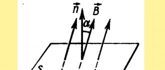
The role of flip-flops is to convert the input analog signal into a digital one and invert (flip) the logic levels. The inversion is clearly explained by the diagram in Figure 4.
Rice. 4. Visual diagram of signal inversion
The device takes into account only parts of the signals that exceed specified thresholds, producing logical zeros and ones at the output. Each time an ascending or descending signal switches the trigger as it passes the upper or lower threshold. Simply put, voltage dips are compensated by inverted trigger pulses.
A simple flip-flop circuit is shown in Figure 5.
Rice. 5. Visual diagram of connecting rs-triggers
The gaps between threshold values are called hysteresis. The shape of such pulses is used for noise reduction during switching of logic signals. The signal from the contact is sent to a circuit that has a static transfer characteristic in the form of a hysteresis loop (Schmidt trigger). Only after this the signal from the trigger outputs is fed to the input of the digital device for clocking.
Using reed switches
It was mentioned above that the presence of mercury on the contacts suppresses chatter. But it is well known that the vapors of this liquid metal are very poisonous. It is not safe to use them in open designs, such as tact buttons. But the contacts can be placed in a sealed flask, which allows the use of mercury. Such structures are called reed switches.
The reed switch contacts are controlled by an external magnetic field.
To do this, you can use permanent magnets or electromagnetic induction. The devices can be used in low-power circuits. They have a long service life because the contacts in them do not wear out. No tags for this post.