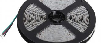
Let's figure out how a battery-powered LED strip is powered. At the same time, we’ll learn how to calculate the expected work life and decide whether this method is suitable, taking into account the task at hand and the materials available.
LED strips are designed for an operating voltage of 12 or 24 V, the standard voltage in the network is 220 V. By default, the problem is solved by purchasing a power supply, but if desired, everything can be solved with ordinary batteries.
Installation option without interfering with the electrical network
You can install and connect LED lighting in your car yourself without interfering with the vehicle’s electrical network. Let's look at this method using the example of connecting a waterproof RGB strip to four contacts. Here you will need:
- four connectors or terminals;
- controller designed for 12 volts (for passenger cars). It is installed to make it possible to control the backlight;
- stranded wire. It should have the same colors as the controller;
- silicone sealant.
The installation process will be discussed using the example of installing the tape under the dashboard inside the cabin. All subsequent actions look like this:
The tape is cut into the required fragments and then soldered using a soldering iron. You can also use connectors for connections, this method will be many times more expensive;
Tape soldering process
- then all places that have been soldered should be treated with silicone glue;
- we install the tape where it should be to illuminate the required area;
- all wiring must be carefully soldered and then hidden under the skin of the car;
- the ends of the tape should be connected to the controller. To do this, you can follow the following diagram;
Controller connection diagram
To connect a lighting product to the cigarette lighter, you can simply upgrade your car charger for your mobile phone. To do this, one of its wires needs to be soldered to the fuse, and the second to the right metal ear. As a result, the stabilizer will be bypassed. After that, close the charging case and insert it into the controller;
Then we insert the charger into the car's cigarette lighter.
Ready backlight
Now you can control the light and music using the remote control.
Mounting methods
How to attach round neon? You don’t need to invent anything here, just stick it on any surface.
A drop of superglue or transparent silicone is enough. With such points you can easily secure the entire backlight.
Some people use thin strips of transparent tape or fishing line, but the appearance of such fasteners deteriorates a little when illuminated.
Models with a skirt are widely used to illuminate the floor. No glue, tape, etc. is required here at all. The backlight is easy to dismantle and change without any harm to the baseboard.
In addition, they are also used to illuminate instrument panels in cars.
The protrusion skirt is neatly hidden in the gaps and can also be easily dismantled if necessary.
It can also be pierced without harming the backlight itself, or completely cut off in those places where it interferes.
How to correctly connect a diode to a car's electrical circuit
The diagram for connecting LEDs to a 12-volt car battery is no different from the diagram for any other power source that has the same voltage. One of two methods is used - through a resistor or through a stabilizer (special chip). However, it is necessary to take into account that the voltage of 12 volts is a conventional value. More often it is 14 V and even more (up to 17 V). The jumps are due to the lack of a stabilizer in the car. When making calculations, you need to insert exactly these numbers into the formula.
By turning on the resistor, part of the voltage is removed from the chain, which can damage the LED. The main disadvantage of this circuit is the conversion of unclaimed current into heat. This requires installing a resistor on the heatsink, which creates additional complications. Additionally, the resistor does not control voltage. If it drops, the glow of the lamp decreases; if it rises significantly, the lamp may burn out.
When using a stabilizer, the microcircuit also converts excess voltage into heat. The main advantage of this option is the ability to maintain a certain voltage level. This means that if it is necessary to connect several light bulbs, the total power of which is less than the power of the stabilizer, a parallel connection is used. A radiator must also be connected to the chip.
Assembly sequence:
- find in the documents or measure the voltage of the LED light bulb(s);
- make a diagram;
- calculate and buy a resistor (driver);
- find the polarity of the LED light bulb legs;
- solder components;
- install an LED light bulb and a resistor on the radiators;
- connect the battery.
It is advisable to measure the voltage and current in order to adjust the indicators in time.
If something is wrong, you will have to select another LED.
Power calculation - formula
One of the main questions is how to determine the required amplifier power? Everything here is quite simple and resembles the calculation when choosing a power supply.
So, to find out what kind of RGB amplifier you need, multiply the power of one meter of tape by its entire length and by the safety factor (K = 1.2).
This coefficient is necessary so that the device does not overload and works properly for the entire declared service life.
Let's look at everything using a specific example. Let's say you need to connect 20 meters of LED strip RGBW SMD 5050/60 diodes per meter.
The power of one meter of such a product is 14.4 W/m.
In this case, the amplifier must be selected according to the formula:
P=14.4*20*1.2=345.6W
If you pay attention, the boxes of these devices usually indicate the amperage and input voltage, but not the power in watts. What to do?
Everything is even simpler here. To get the coveted calculated figure, we will use the formula known from the school physics course: I=P/U
In the above example we have:
It turns out that in this case you need a 30A RGB amplifier.
If you need to connect not RGB, but a monochrome one-color tape, the best option would be to use only one “negative” terminal - R or G or B. Choose any one to your taste, there is no difference here.
The only thing you need to consider is that the total amperage of the amplifier must be divided by three.
And it is with this power that you should select a monochrome LED strip.
Set contents
When purchasing an LED strip, you may want to pay attention to ready-to-use lamps. This is an easier way to illuminate areas in your home.
With some diligence, you can now find lighting fixtures to suit every taste and budget. In addition, sometimes assembly from separately purchased elements can be much more expensive than ready-made products. The tape itself cannot provide lighting without additional devices. For it you should also purchase a power supply, an adapter, an adapter and a certain amount of wire with which it all is connected. For a professional this will not be difficult. But an amateur will have to write down all the required characteristics, draw a connection plan, put all the parts together, try not to mix up the wires and thus not destroy all the purchased materials. And the result may be far from the plan.
At the same time, the master, when assembling the lighting, is able to control the quality of the material used, the work on the installation of the structure and placement. If you want to become a real master and decorate and ennoble your home as much as possible, you need to start small and simple, gradually moving on to more complex elements.
In conclusion, it should be recalled that when assembling more economical lighting, you should not purchase cheap materials. As they say, the miser pays twice, or even more. There are many offers from Chinese craftsmen on the Internet. It’s just that the lack of any guarantees, and sometimes even markings, makes you wonder whether their use will lead to a sharp reduction in service life or to more irreparable problems in the form of an accidental fire or harm to health. It is worth paying attention to the choice of not only the material itself, but also the manufacturer.
To solder or not to solder
The battery is attached using soldering. If there are several batteries, it is not necessary to solder each one separately - we use a battery box with 2-6 compartments.
When connecting using a power supply or box, as well as in designs with controllers and amplifiers, connectors can be used. Compared to soldering, this method is simpler, but:
- the connectors gradually begin to oxidize;
- plastic melts at high temperatures;
- diodes located at the connection points lose brightness.
Soldering is not necessary when using power supplies, and connecting with batteries will be safer and more reliable for long-term operation. But you will need certain tools and materials. Connectors are convenient to use in lighting of complex designs, especially high-rise ones.
Working with a 220 V network
The simplest mains voltage indicator without a power source is made from a resistor, a current limiter (transistor), a rectifier (diode) and any LED. Resistor resistance is 100 - 150 kOhm.
Diode characteristics:
- current 10-100 mA;
- voltage 1-1.1 V;
- reverse voltage 30-75 V.
At 220 V, 3 Hz, the LED lights up. You can adjust the frequency and increase the brightness by changing the capacitance of the capacitor. Such an indicator operates at a minimum voltage of 4.5 V. In addition to the mains current, it can determine the serviceability, on and off state of an electrical appliance.
DC Voltage Check
To check the 12-volt network and the integrity of the connections, you can make another LED indicator (you need 2 multi-colored LED elements). To limit the current, you can use a resistor with a resistance of 50-100 Ohms or an incandescent light bulb with low power. One of the LEDs lights up when a voltage of the appropriate polarity is connected.
You can add a capacitor, a diode and 2 transistors to a homemade indicator for a 12 V network. The field-effect transistor stabilizes the current. A capacitor that protects the diode from voltage surges is needed with a capacity of 0.1 μF, non-polar. A resistor with a resistance of 1 MΩ is the load of a bipolar transistor. When testing a constant voltage network, the diode checks the poles. If the current is alternating, this element cuts off the negative half. When voltage is applied, the current value is determined by the bipolar transistor and the resistance of the resistor (500-600 Ohms).
This device is suitable for working with alternating and constant voltage networks of 5-600 V.
Indicator for microcircuits - logic probe
Devices for indicating microcircuits are called logic probes. This indicator is three-level (3 LEDs are included in the circuit).
A logic probe allows you to:
- determine phase, short circuit, resistance of the electrical network;
- establish the presence of voltage 12 - 400 V;
- determine the poles for direct current;
- check the condition of diodes, transistors and other parts;
- determine the integrity of the electrical network by ringing;
- diagnose relay and coil breaks;
- ring chokes and motors;
- determine the terminals of transformers.
The power source is a 9 V battery. When the pins are closed, a current of 110 mA is consumed. After opening, no current is consumed; there is no need to install a switch or mode switch.
When checking a network with a resistance of 0 - 150 Ohms, 2 LEDs light up, and when the indicator increases, one LED lights up. At 220-380 volts the third one lights up, the rest flicker. If the circuit is broken, the LEDs will not light up. At zero on the contact 0.5 V, one transistor opens (KT315B), at 2.4 V - the second (KT203B).
It is possible to replace transistors with others having similar parameters.
Voltage indicator on two-color LED
Another simple indicator chip - with a two-color LED. Some home craftsmen use it to determine the operating mode of the lamp. For example, a basement light switch equipped with an indicator is mounted on a staircase. If it is on, the glow is red, after turning it off it is green.
Option for car
The circuit for indicating the battery charge and vehicle network voltage consists of:
- RGB LED;
- 3 zener diodes;
- 3 bipolar transistors (BC847C);
- 9 resistors;
The level is determined by color. Green glow at 12-14 V, blue at 11.5 V, red at 14.4 V).
If no errors were made when assembling the circuit, one of the resistors (2.2 kOhm) and the transistor (8.2 V) determine the minimum voltage limit. When the indicator decreases, the transistor corresponding to the blue glow connects the crystal.
If the voltage does not decrease or increase, the current passes through 2 resistors, a 5.6 V zener diode and an LED, a green glow appears (the transistors corresponding to red and blue turn off). When the voltage increases to 14.4 V, the red light comes on.
Assembly and connection
Let's make sure that we have everything we need for work:
- the tape lies nearby, the required piece with the required number of diodes has been selected, the specifications are known;
- batteries have been purchased, capacity, voltage, operating time have been calculated; if there are a lot of batteries, the box has been prepared;
- soldering iron with a power of 25-40 W, flux, solder;
- flexible wires (preferably with multi-colored insulation), the cross-section can be small, 0.5-0.75 mm2;
- knife-nippers for stripping insulation;
- a piece of sandpaper or something similar for cleaning contacts;
- optional toggle switch and connectors.
Remember that with a series connection, the total voltage is the sum of the voltages of all batteries. When parallel, it is equal to the voltage of each individual element.
Let's start connecting:
- We clean the contacts on the batteries - we process the plus and minus with sandpaper.
- We tin the ends of the wires.
- We solder one wire to the stripped plus of the battery, the other to the minus.
- If you connect a toggle switch, a wire from the battery is soldered to its input, the output goes to the minus of the tape.
- We make neat cuts in strictly marked areas of the LED strip (usually the cut line is between pairs of solder contacts).
- Plus, minus, as well as operating voltage are written directly next to the contacts. RGB contacts are always a disadvantage.
- The plus soldered to the battery (or the positive wire coming out of the box) is soldered to the plus on the tape, the minus (or the output of the toggle switch) is to the minus. A soldered “green” pin will make the strip glow green, and a red pin will glow red. Sometimes the minus is marked as GND.
- Connectors can connect either individual sections to each other or the entire strip to a power source or controller. Each type (RGB, RGBW) requires its own connector.
- If necessary, repeat the steps above with the remaining batteries and sections of tape.
- There should be no solder residue left on the contacts.
On colored tapes the 4 pins are very close to each other. We make sure that when soldering, a tin track does not form that covers several contacts at once. If this happens, reheat them and use a toothpick to remove excess tin between the contacts. We ignore it, and at best the colors will be mixed up; at worst, either the tape, or the power supply, or all at once will burn out.
When working with a soldering iron in weight, do not forget about safety glasses and gloves.
There are several ways to secure the LED strip:
- adhesive layer on the back of the tape;
- additional attachment with double-sided adhesive tape;
- gel superglue;
- aluminum profiles.
Two methods of connecting a diode strip are fundamentally different in scale: battery - wireless, suitable for local tasks; with power supply - reliable, for large projects. The charge level relative to the electricity consumed will help you find out how often you will have to change the batteries and how many of them are needed for uninterrupted operation. Those who are not confident in using a soldering iron take a battery box or power supply and connect it using a connector.
The ability to connect an LED strip without a power supply will eliminate problems with laying wires. And this is the only way to make it work when there is no electricity.
When will it come in handy
If compactness and mobility are important for business, we neglect the power and area of lighting. The connection is convenient to use when you don’t want to occupy an outlet or there isn’t one nearby at all.
We work with batteries in the following situations:
- interior lighting without fussing with wires and wondering where to put the bulky block;
- lighting of the utility room, garage - any place where there is no electricity;
- illumination for something moving - a bicycle, scenery, a costume for performances;
- I don’t want to buy a power supply and calculate its power for our task;
- lighting is used one-time or for a short time (at outdoor events, holidays);
- I need the light urgently, but something has happened to the power supply.
Circuits of stabilizers and current regulators
There are at least four options for making 12-volt voltage stabilizers for cars with your own hands:
- On a roll.
- On a pair of transistors.
- On an operational amplifier.
- On a pulse stabilizer chip.
Let's look at the main features of each of the modifications under consideration.
On a roll
To assemble a simple stabilizer for 12-volt LEDs for a car with your own hands, you will need:
- Microcircuit LM317 or KREN8B (more precisely KR142EN8B), or KIA7812A.
- 120 ohm resistor.
- Printed board or perforated panel.
The images clearly show the location of the main components of the simplest stabilizer circuit for LEDs in a car:
In the second circuit, a 1n4007 rectifying diode is used at the input from the battery.
On two transistors
One of the most popular automotive voltage stabilizers for 12-volt LEDs, which is also assembled by hand, today is a circuit with two transistors.
An alternating voltage of 12 volts is supplied to the diode bridge VD1 - VD4, rectified and, passing through filters C1 C2, smoothed. Next, the current goes to the parametric stabilizer VD1 and passes to resistor R2. Then from its engine it is transmitted to the key of the composite transistor VT1 VT2. The level of its openness is determined by the state of the variable resistor R2 - in the lower position of the regulator, the transistors are closed and the voltage is not supplied to the load, and in the upper state of the regulator R2 it is maximum and the transistors are completely open, voltage is applied to the load.
The given model of voltage stabilizer for cars is most often used for daytime running lights based on LEDs and allows you to successfully adjust the parameters of the on-board current to the characteristics of the lighting device.
On an operational amplifier
It makes sense to make a 12-volt voltage stabilizer for LEDs in a car yourself when there is a need for it to operate in an expanded range of operating parameters. Below is a diagram of such a device. Its main feature is that the amplifier itself is included in the feedback circuit and is powered directly from the stabilizer output. The device is characterized by a stabilization coefficient of about 1000, while the output resistance is no more than 10 μOhm with an efficiency of about 50%. The nominal load current is at least 200 µA, and with double-amplitude output voltage ripple - less than 60 µV.
Among the main features of his work are:
- The operating temperature range is from -20 to +60 degrees.
- Thermal drift of output voltage is less than 0.05%.
- Possibility of increasing the output voltage to 27-30 volts.
To solve the last problem, you need to install a 200 Ohm resistor between pins “7” and “+25”. The cascade of transistor VT1 acts as a dynamic load for VT4 and at the same time increases the overall gain. Transistor P702A can be replaced with analogs of P702 or KT805, while KT603G can be replaced with P308 or P309, respectively, and KT201V and KT203V with MP103 or MP106.
On a pulse stabilizer chip
When a high efficiency is required from a voltage stabilizer for a car, it is better to assemble the device yourself using pulse components. The most common is the MAX771 circuit presented below (or analogues 770, 772).
The pulse type stabilizer has an output power of 15 watts. Circuit elements R1 and R2 separate the voltage readings at the output points. In the case when it becomes higher than the base one, pulse rectifiers simply reduce its output value. Otherwise, the device will, on the contrary, increase this parameter at the output.
Do-it-yourself installation of a pulse voltage stabilizer for LEDs in a car is reasonable when its value exceeds 16 volts. If increased load drop occurs, an operational amplifier should be added to the circuit.
Connecting the LED strip directly to a 220 V network without a power supply
The vast majority of commercially available LED strips are designed to be connected to a 12 V DC power supply. Less common are LED strips with a power supply of 5 volts or 24 volts and higher. You cannot connect such lighting devices directly to a 220 V AC network - not even a second will pass before all the SMD light-emitting diodes and resistors will simply burn out.
Nevertheless, there is one working method that allows you to power a low-voltage LED strip from a 220 V network. To implement it, a 12 V strip of any type and color of light is cut into 24 equal segments. Then they must be connected to each other in series. To do this, use a short wire to connect the negative contact of the first segment to the positive contact of the second segment. Next, solder the wire to the minus of the second and plus of the third segment, and so on. As a result, instead of a parallel connection, you get a chain of series-connected sections of LED strip, capable of withstanding a voltage of 288 volts.
obrpr
Despite the fact that this scheme is quite workable, it has a number of disadvantages:
- on each of the segments at the soldering points there is a life-threatening high voltage;
- the design has low reliability due to the huge number of connections;
- low ergonomics of the finished product.
In order not to have to independently convert the LED strip from 12 to 220 volts, you can buy a ready-made industrial strip designed for direct connection to a single-phase household AC network. Its design difference is that SMD LEDs are connected in series in groups not of 3 pieces, but of 60 pieces, and a diode bridge is included in the delivery package. Detailed information about such LED strips, rulers and modules can be found in a separate article about 220 volt LED strips.
What you need to know about soldering
The most important thing in working with LED strips is cutting them correctly into separate fragments and soldering them. In order for everything to go well, you should know the following nuances of carrying out this type of work:
- The product needs to be cut only in special places. Otherwise, the conductive contacts will be damaged and the device will be damaged;
Place for cutting tape
- you need to solder carefully, applying the soldering iron tip to the contacts and wires for just a few seconds;
- the wires must first be tinned;
- After soldering is completed, the contacts should be cleaned of solder residues.
By adhering to these recommendations, the process of soldering individual fragments of the product and connecting to a power source will be as easy and quick as possible.
Serial connection
When connected in series through a current-limiting resistor, several LEDs are assembled into one chain, and the cathode of the previous one is soldered to the anode of the next one:
In the circuit, one current (20mA) will flow through all LEDs, and the voltage level will consist of the sum of the voltage drop across each. This means that using this connection diagram, you cannot include any number of LEDs in the circuit, because it is limited by voltage drop.
Voltage drop is the level of voltage that a light-emitting diode converts into light energy (glow).
For example, in the circuit the voltage drop across one LED will be 3 Volts. There are a total of 3 LEDs in the circuit. Power supply 12V. We consider 3 Volts * 3 led = 9 V - voltage drop.
After simple calculations, we see that we cannot include more than 4 LEDs (3 * 4 = 12V) in a parallel connection circuit, powering them from a regular car battery (or other source with a voltage of 12V).
If we want to connect more LEd in series, we will need a power supply with a higher rating.
This scheme was quite often found in Christmas tree garlands, however, due to one significant drawback, modern LED garlands use a mixed connection. We'll look at what the drawback is below.
Disadvantages of daisy chaining
- If at least one element fails, the entire circuit becomes inoperative;
- To power a large number of LEDs you need a high voltage source.
Connecting a 12 volt LED strip via a power supply
Most often, the LED strip is connected to the network via a 12 volt power supply (less often 24 or 36 volts). If it is necessary to create lighting effects or regulate the intensity of the glow, a controller is additionally included in the circuit
When purchasing a unit, you need to pay attention to the power indicated on the packaging.
Most often, cutting to dimensions corresponding to the surface on which the device will be installed is required. During work, segments of different lengths remain; they must be connected correctly. The easiest way is LED connectors, to which contacts are applied, then the cover is snapped on. If there are many segments, not everyone is satisfied with the cost of these elements.
Soldering is cheaper and more reliable. The soldering iron tip should be 2 mm wide. The surfaces to be soldered must be tinned (covered with a layer of solder) on both sides. To do this, peel off the adhesive tape. One pad overlaps the other, the overlap is approximately 3 mm. To solder, you need to heat them with a soldering iron.
Another option is soldering with wires (cross section 0.8 mm). Copper wires are cut into pieces of the required length, 8-10 mm of insulation is removed from the ends, and after tinning, the excess 5-7 mm is cut off. The ends of the wires are applied to the tinned contact pads; when touched with a soldering iron, a beautiful soldering is obtained.
There is always a plate on the body of the 12-volt power supply describing the technical characteristics.
Terminals:
- L and N – connection to the network;
- FG – grounding;
- 3 G – connected in the housing, for connecting the minus of the tape;
- 3 V+ - connected in the housing to connect the plus of the tape.
The wires are soldered in the same way as when splicing, but it is better to twist the ends into a ring. The power cord wires can be swapped during soldering; the ground wire is connected to the corresponding terminal.
If several segments are connected, wires with the same polarity are soldered to one terminal.
If you need to connect many short sections to a 12-volt unit located at a considerable distance from it, main wiring is laid. The segments are connected to it in any convenient way (terminal blocks, connectors, soldering).
When creating a system from segments with different capacities, they are connected in any order, in series or in parallel. The main thing is that the total length does not exceed 5 meters.
For two or more multi-color ribbons, one 12-volt unit and one controller may not be enough. To reduce the load, amplifiers are included in the circuit. They are installed between the segments to ensure uniform illumination.
If the density of the elements on the strip is high, overheating is possible during operation. An aluminum profile that dissipates heat is required for mounting.
When it might come in handy
Powering the LED strip from any batteries will be the right solution in situations where you need to create small-length and low-power lighting.
Note! If the LED backlight is long, you will still have to use the traditional method and connect it to the mains voltage via a power supply.
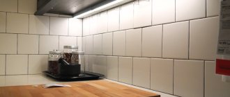
Cabinet lighting with LED strip
Using a small battery-powered LED strip, you can quickly and easily power your cabinet. At the same time, you can illuminate the closet with clothes in the bedroom, as well as wall cabinets in the kitchen. In addition to kitchen units and cabinets, such lighting can be arranged for shelves, whatnots, paintings, etc. It is independence from the mains that is the main advantage of operating an LED strip on batteries. This method of powering the light source frees up your hands and allows you to create more original and non-standard lighting for various interior elements. It is worth noting that this connection method will be relevant for rooms in which, for some reason, there is no wiring. Also, connecting the tape to the battery can be organized in situations where there are power outages. In this way, you can not only illuminate such non-standard rooms, but also create an atmosphere of celebration and comfort in them.
Note! By using waterproof and sealed models of these LED products, you can create spectacular lighting for the kitchen, bathroom or balcony.
In addition to furniture (for example, kitchen units and cabinets), such a lighting installation can be placed:
- on clothes when creating light suits;
- on sports equipment;
- built into cars and other vehicles (motorcycles, mopeds, bicycles);
- lighting in apartments and houses in hard-to-reach places.
How to choose a ribbon
First you need to choose the right tape. An important factor when choosing is the purpose for which the backlight is installed. The tapes vary depending on the number of light bulbs located on one meter of tape. There are 30, 60, 120 and 240. The more bulbs, the brighter the light.
Next, you need to decide on the place where the tape will be located. Like any electrical device, it is afraid of moisture. But there are several types of tapes adapted to aggressive environmental influences. This can be found out by reading the label. IP20 is practically not protected. It should not be placed above the sink in the kitchen, bathroom or outdoors. Rather, she will have to illuminate bookshelves or paintings in the interior. IP65 is protected enough for use in the kitchen or bathroom. It also works great with outdoor lighting. IP68 is an absolutely protected tape that is easily suitable even for lighting swimming pools.
For further operation of the tape, you need to understand what kind of backlight is needed - monochrome or multi-colored, warm or cold
And, of course, pay attention to the size of the illuminated surface. All this should be taken into account when deciding on the purpose of the tape.
When it's no use
If reliable lighting is important or a large area is covered, batteries will not be suitable. Power supplies are more convenient (or indispensable) when you want:
- carry out work on lighting a large room or many of them at the same time;
- design facades, cornices, outdoor advertising;
- leave the backlight on for a long time;
- use lighting effects (flickering, fading, overflow);
- highlight inaccessible or high-altitude areas of the room, where it is not possible to constantly solder and resolder batteries without the risk of going crazy.
The power supply becomes warm during operation. He will need a place isolated from other things, but easily accessible to humans. Block housings are either open or semi-sealed, depending on the intended location.
How to properly connect an LED strip in a car
You can connect the LEDs in your car to the on-board network or directly to the battery (not advisable, more on that later).
The on-board electrical network of the car does not correspond to the nominal power parameters of the LEDs, since the voltage taken from the battery reaches 14.5 Volts. This is not fatal for LEDs, but it significantly reduces their service life.
The second risk factor for direct connection to the on-board network is significant current drops. Any car has units with significant power draw from the battery - starter, head lighting, air conditioning, electric power steering. They consume hundreds of watts, and currents reach tens of amperes.
You've probably noticed how, when starting the engine, the headlights go out, the radio and on-board computer turn off, and turning on the air conditioner "cuts down" the volume of the music. And this is when the wiring lines are separated through a distribution box and there are current stabilizers in the equipment.
Use stabilizer
Any LED can operate for a long time only in a narrow range of currents and voltages. For example, an SMD 3528 LED element requires 2.8-3.4V and 0.02A for power supply. Thanks to the limiting resistors on the tape itself, they only feel comfortable at a mains voltage of 12V.
To connect the LED strip to the 12V of the car, use a stabilizer; it is connected to the gap in the positive wire from the battery. You can assemble it yourself. Below is a diagram using the example of a voltage stabilizer LM 7812. It has an output voltage of 12V and produces a current of up to 1A. This is an outdated model and requires additional cooling.
More modern switching stabilizers will be a good replacement for outdated analogues. Here are the characteristics of a regular switching stabilizer from Aliexpress:
- Wide range of input voltage (4-36V) and adjustable output (1-36V);
- adjustable output current (0-5A);
- protection against overheating and short circuit;
- a wide range of operating temperatures is declared -40 +80 degrees;
- Conversion efficiency 96%;
- They cost around $3-4 on Ali (220-270 rubles).
Switching stabilizer 12V
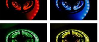
Connecting RGB strip
When connecting an RGB strip, an RGB controller is added to the circuit, which regulates the power of each color LED and allows you to obtain any color. It is connected after the stabilizer, before the RGB strip.
Details about the principle of operation and connection of RGB strip.
Connection diagram for RGB tape in a car
When connecting the diode strip to a car, you should avoid bending it. Any break will lead to a rupture of the conductive coating. If you need a sharp turn, make a break and connect the ends with connectors.
Use connectors
Soldering is the most reliable method of attaching wiring, but it is not always convenient. In conditions of limited space, there is always a risk of damaging the car interior trim with a hot soldering iron tip, and soldering in an acrobat position is not comfortable. To connect the segments, you can safely use connectors with pre-soldered wires.
They clamp the contacts tightly and are quite reliable even in conditions of constant vibration. But it is better to fill the places of such connections located outside the car with sealant or hot-melt adhesive. If you had to make additional holes in the machine body to route the LED strip wiring, carefully treat them with an anti-corrosion compound and, if possible, seal them. The connection points of the wires should be covered with heat-shrinkable tubing for reliable insulation.
Battery powered
If buying a battery is expensive, but there is nowhere to charge it, then you can make the LED strip glow using batteries. Let's look at the 3 most common connection options.
Option No. 1 involves the use of 6 1.5 V AA batteries connected in series. Why exactly 6 pieces? Because the LED strip, even when powered by 9V, will operate at approximately half its power. Firstly, this level of light from the tape is quite enough to illuminate something. Secondly, half the current will flow through the LEDs (nonlinearity of the current-voltage characteristic), which will significantly extend the battery life. But if desired, you can increase the number of batteries to 8.
There are two ways to assemble a battery-powered LED backlight circuit:
- using short wires, all batteries are soldered together in series, secured with electrical tape, and two wires are soldered to the extreme “+” and “–” to connect the LED strip;
- 6 batteries are inserted into the cassette (container), observing the indicated polarity. The wires coming out of the cassette are clamped together with the LED strip in the connector.
The capacity of an AA battery is approximately 2 times greater than that of an AAA battery from the same manufacturer.
Option No. 2 involves the use of power in the circuit from one 9 V Krona battery. The capacity of the alkaline crown is approximately 0.5-0.6 Ah. This means that, for example, a 30 cm long SMD 3528 tape will shine continuously for 5 hours. The crown is often used for LED tuning of a bicycle.
Option number 3 involves the joint use of a battery from a phone (smartphone) and a step-up converter up to 12 volts. In this configuration, LED backlighting has several significant advantages:
- reliability and durability;
- compactness (the size of the converter is comparable to a flash drive);
- reasonable cost (3.7 V-12 V converter – $2, battery – $10);
- the battery can be easily charged from a smartphone or charger, and its capacity reaches 2000 mAh;
- Light emitting diodes shine at full brightness.
You can connect batteries and accumulators of any type to the converter. The main thing is that their voltage matches the input voltage of the converter.
Since the advent of LED lighting, it has been actively used in all cars.
At the same time, in addition to replacing conventional lamps with diode ones, many craftsmen have found various ways to use LED strips. Moreover, even in those places where there has never been illumination or illumination.
You can install additional lighting in a car in several parts and units:
- dashboard
Here you can get by with very short sections that you have left after repairing the lighting in your house or apartment.
- car interior or doors
What LEDs can be connected to 12 Volts
Sellers claim that they sell LEDs that can be connected to a 12 V power source. In fact, this statement is incorrect. An ice light bulb does not have a strictly defined operating voltage, so we can only talk about a light source made of diodes.
It is necessary to determine what happens in the ice lamp during the glow. In this process, the most important 2 parameters are: maximum and operating (necessary for glow) current. They are taken into account in the production of ice matrices, but not when choosing a current source.
The voltage on the light bulb is most often from 1.5 to 3.5 volts, the figure depends on the color of the light bulb.
The lowest value is red diodes, the highest is super-bright. A 12-volt luminous diode is a matrix (assembly), which can include any number of crystals connected in series. There can be several similar chains; they are connected to each other in parallel. No tags for this post.
How long does it work
To calculate how many batteries we need and how long they will last, we look for the amount of current consumed by the LEDs. This value differs for different types of equipment and is indicated in the documentation. The quantity is indicated both per LED and per unit length.
Having calculated the total amount of current consumed, we select batteries of the required capacity. The 18650 lithium batteries have a capacity of 2600 mAh - with a consumption of 2600 mA (or 2.6 A), they can provide continuous light for an hour. Five meters of diode strip for 30 diodes, depending on the specification, can consume a current of 1-3 A; for an hour and a half of operation they will require two 18650 batteries.
The quality and operating time depend on the accuracy of soldering or the connectors used.