Connecting a regular LED strip does not raise any special questions for most users.
What to do if your feed is not simple, but addressable or digital? What features and differences does this tape have?
Most of the videos that fill YouTube explain in detail how to connect it using Arduino - “solder the wires to these contacts on the Arduino, upload my sketch, etc.”
What if you have no desire to understand this issue and get into the jungle of programming? 99% of users want to buy a finished product, press a button and enjoy the backlight.
In this case, you will have to purchase a special SPI controller for your smart tape.
At the same time, you can independently adjust the colors, speed and dynamic modes on a regular smartphone.
What is addressable LED strip?
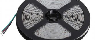
First of all, let's look at what a digital LED strip is, how does it work and how does it work? In another way, it is also called targeted, smart or “running fire” tape.
The main difference from conventional products is the presence of microcircuits on the board. Moreover, they can be built into the LED itself.
So are external ones.
They allow you to control the operating modes of each segment separately. This way you can directly turn on and off any LED or pixel.
In this case, a pixel is a cell of one or more LEDs at once (usually 3 pieces).
You can control both the brightness and color of any diode in the strip and at the same time create absolutely stunning lighting effects:
- for auto
- for aquarium
- on the facade of the house
- on the Christmas tree
The variety of options will depend only on your imagination.
Where can I buy it?
Addressable LED strip can be easily found in any specialized store. Among the proven options, which are distinguished by low price tags and good quality of the product, we can recommend the online store www.giant4.ru. Addressable LED strips can also be purchased on the well-known AliExpress.com site.
To avoid problems with low-quality products, when purchasing a product on AliExpress, you should carefully study the product and customer reviews.
Difference between ws2812, ws2812b, ws2811 tapes
The most common models with built-in microcircuits are labeled WS2812 or WS2812b. With external ones – WS2811.
How does the ws2812 model differ from the ws2812b? The first ones have 6 contacts (PIN) for control, and the second ones, with the letter “b”, have only four.
At 2812, the power supply for the LED and the chip are separated. In 2812b, the power supply for the integrated driver and LED is allocated to one PIN (VDD).
What are the main differences between ws2812b and ws2811?
- ws2812b – works from 5v
- ws2811 – 12v power supply (the latest 5v models were discontinued in 2015)
WS2812 controls clusters of one diode at a time, WS2811 controls three LEDs simultaneously.
A significant disadvantage of ws2812 diodes is that if at least one of them burns out in the chain, then all further LEDs after it immediately stop working.
Design of the lamp element
Each addressable LED contains a minimum number of pins:
- U power (VDD);
- common wire (GND);
- data input (DIN);
- data output (DOUT).
This allows elements with built-in emitters to be placed in 4-pin packages (WS2812B).
WS2812B pinout.
Microcircuits with external LED connections will require at least three more pins to connect LEDs. As a result, a standard package with 8 pins has one free leg, which developers can use for other needs.
WS2818 pinout with additional data output.
Thus, the designers of the WS2811 chip used a free output for the speed switch, and WS2818 - for a backup data input (BIN).
Address strip ws2813
Therefore, progress did not stand still and later more advanced tapes were developed - ws2813 (5V), ws2815 (12V).
These tapes have a fourth duplicating track added. Data is transmitted through it if any of the diodes burns out and fails.
How it works? The signal in the normal state goes to the Data Input (DIN) and exits the chip to the Data Out (DO). Through this chain, data flows throughout the entire tape.
When the first chip fails and data stops coming out of the DO, the redundant track keeps the signal flowing to the BIN connector.
The second chip analyzes the loss of the signal on DIN, but sees its presence on BIN and continues to work as if nothing had happened.
The most important thing is that if the first diode fails, there is no short circuit between VDD and GND.
Mistake #1
Never use the backlight on WS2812b type chips when shooting video.
If you want to shoot a movie or video clip with such backlighting, then use only WS2813 tape, no less.
The point here is the frequency of regeneration. For older models it is only 400Hz.
This may be invisible to the human eye, but the camera will not forgive you for such a mistake.
Here is a very visual experiment with such LEDs in dynamics. Connect a piece of tape with two different chips and try waving them from side to side.
The result on the captured still frame.
It should be noted that this is just one connected LED 2812b and 2813, and not several of them in one row.
Connection to power supply and controller
Signals via a programmable tape are transmitted from a controller with SPI chips via digital communication protocols. After 24 bits of information have arrived at the first LED, this diode goes into transmission mode.
All data that reaches it is transmitted to the output, that is, to the next diode in the series chain.
Mistake #2
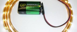
If you directly connect a power supply to such a tape, it will not work.
In this case, the presence of a controller is mandatory.
The controlled LEDs need to be “loaded” with their colors.
In addition, the principle of signal transmission between elements is also different. If you look closely, you can see arrows on each smart tape in strictly one direction.
They show that the control signal will be transmitted from one element to another in this direction, and not vice versa.
Mistake #3
Built-in microcircuits are afraid of polarity reversal!
Therefore, if you are connecting not through special connectors, but by direct soldering, always check “+” and “-” (GND).
Otherwise, your addressable LED strip will burn out the first time you connect it.
"Running Fire"
The so-called SPI tape, which in everyday life is called “running fire” because of the most common lighting effect that is built on it, deserves special consideration. The difference between such a tape and the types considered is that the data bus contains two lines - for data and for clock pulses. For such devices, you can purchase an industrially manufactured controller with a set of effects, including the aforementioned “running fire”. You can also control the glow from conventional PIC or AVR controllers (including Arduino). Their advantage is increased noise immunity, but the disadvantage is the need to use two controller outputs. This can be a limitation for building complex lighting systems. Also, such devices are characterized by a higher cost.
SPI tape with a two-wire control bus.
Wires and connectors
A digital tape at the end has at least not two, but three wires.
- V+ (5V or 12V)
- V-(GND)
- control wire
Two of them are normal power, and the third is responsible for the direction of the signal. Special connectors are soldered to the wires at the ends of the ready-to-use product:
- DI (Digital Input) or digital input at the beginning of the tape
- DO (Digital Output) digital output
If you have such connectors, you will not be able to connect the tape with the wrong side. The second DO end is required when increasing the length of the light structure.
Mistake #4
But without such connectors, the beginning and end of the tape can be confused.
In this case, nothing will burn or glow.
Mistake #5
The power cables from the controller are too long.
If you have a situation where the tape does not light up until you touch and run your hand over the power wires, then most likely they are too long and the control wire is subject to interference.
In this case, try twisting them into a pigtail. It helps in some situations.
Choosing a controller for the address tape
When choosing an SPI controller for smart strips, you need to count not on the backlight power, as is usually done, but on the number of pixels.
These parameters are always indicated on the product body.
As for choosing the power of the power supply, focus on the following indicator. One LED for sw2812b models is approximately 60mA in white light.
Count their total number in the feed, take a reserve of 30% and select a suitable block.
From the power supply, the wires are connected to the controller, and on the other side of the controller the tape itself is powered.
Power can be supplied directly, but a controller is required.
Connection over 5 meters.
If you need to connect more than 5m of smart tape, then to ensure its uniform glow, you cannot simply increase the backlight sequentially. We are talking here primarily about nutrition!
When the number of pixels on the controller allows you to connect a large length, you can easily connect the DI and DO connectors together. But the power supply (5V or 12V) will still have to be pulled separately (in parallel).
There are controllers with additional wires for “extra” power in such a case.
Mistake #6
You cannot connect several pieces of tape in series and at the same time apply an initially higher voltage to them.
For example, take three pieces of ws2812b (5m+5m+5m) and apply 15 volts to them at the very beginning of the tape, counting on a consistent voltage drop.
In this case, you will have to install your own controller for each segment, and somehow guarantee the same consumption of the segments.
Mistake #7
The ribbon glows with a yellowish or red tint instead of white.
Most likely the issue here is an incorrectly selected wire cross-section. Always use a minimum of 1.5mm2.
Lack of color is the first sign of voltage sag. The shift to red is explained by the fact that blue and green colors on the 2812b chip require about 3.5V, but 2V is enough for red.
Therefore, when the voltage on the LEDs drops, the green and blue crystals turn off, and the red one remains on until the last one.
Now the timings
Initially, there is a log on the leg. unit. To switch the LED to signal receiving mode, you must apply a logical zero for 5 ms. After this come the data bits: to transmit a “zero” character, you must submit a logical one, and immediately submit a logical zero. To transmit a “single” character, you must submit a logical one, wait 3 μs, and submit a logical zero. The interval between signals is from 6 to 20 µs. You can see time intervals on oscillograms in different time bases (Fig. 3, Fig. 2, Fig. 1).
After the last information bit is supplied to the bus, a logical one must be applied. The colors set this way will remain lit until you turn off the power or update the color pattern with a new data packet.
And the last nuance - on my tape, when controlling the LEDs in this way, if no data was sent for a long time, and when you try to start transmitting a new data packet, the first LED receives 24 bits, further bits begin to be transmitted to the next LEDs, but does not change its color.
Example: there is a tape, there are 4 LEDs in the tape. In theory, I want to: in 1 second turn everything red, 2 seconds - all LEDs turn blue, 3 seconds - all LEDs turn green. What happens in practice: in the 1st second the first LED is not lit, 2,3,4 are lit in red, 2nd sec - the first LED is lit in red, 2,3,4 are lit in blue, 3rd sec - the first LED lights up blue, 2,3,4 lights up green.
So far I have dealt with the problem in this way: in the initial state there is a log. one, I give an initialization signal (5 ms), 24 bits - a data packet for the first LED, wait 30 μs, again give an initialization signal (5 ms), and send information bits for all LEDs.
Dear forum users, I don’t know, maybe there’s a glitch on my LEDs. Or maybe I’m using the wrong algorithm to interact with LEDs. Therefore, if anyone knows why such a glitch may occur, write in the comments. That's all. Good luck to all!
The correct purchase of LED strip on AliExpress.
What else can be said about the cross-section of the wires? For example, a 2812 tape consumes about 60mA per diode. With a backlight length of 5 meters, the current will be 18 Amps!
According to all calculation tables, such a current requires wires with a cross section of 2.0-2.5 mm2. Even on the tape itself, copper tracks do not provide such a cross-section.
Therefore, if you want normal glow and brightness, even for standard 5-meter sections, always connect power at both ends.
In addition to the cross-section of the wires, the quality of the tracks themselves also plays an important role. Of course, the Chinese will tell you that they have the best products and no one has complained.
But how can you check this without buying the product? Elementary - request information on the weight of the tape. After that, compare identical models from different manufacturers.
For example, for a strip 5m long (60 LEDs per meter) with a weight of less than 100g, voltage drops begin after 1.5 meters!
This is explained by very thin copper tracks or low-quality copper in them.
How to calculate the number of addresses for DMX 512 tape
DMX (RGB)
• 1 pixel = 3 DMX channels (RGBW) • 1 pixel = 4 DMX channels (RGBW)
By having different densities of LEDs on a strip and different lengths, you can multiply it all together and get different results.
For example:
• (8PL30) 30 RGB LEDs/m strip x 5 meter reel = 150 pixels (150 pixels x 3) = 450 channels • (8PL60) 60 RGB LEDs/m strip x 5 meter reel = 300 pixels (300 pixels x 3) = 900 channels • (8PL144) 144 RGB LEDs / m strip x 2 meters = 288 pixels (288 pixels x 3) = 864 channels • (8PX30) 30 RGBW LEDs / m strip 5 m = 150 pixels (150 pixels x 4) = 600 channels • (8PX60) 60 RGBW LEDs/m strip x 4 meter reel = 240 pixels (240 pixels x 4) = 960 channels
Convenient to remember:
• 170 pixels RGB = 510 channels DMX = 1 DMX universe • 128 pixels RGBW = 512 channels DMX = 1 DMX universe