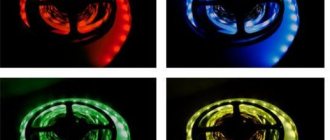
Currently, addressable LED strips (NeoPixel LEDs) based on WS2812 LEDs are widely used in various fields. In this article we will look at connecting such a tape to the Arduino board and learn how to control it in various modes.
Previously on our website, the use of addressable LED strip (NeoPixel LEDs) was considered in the following projects:
- room thermometer on Arduino Nano;
- communication of two Arduino boards over a distance of 3 km using Lora E32.
Now the timings
Initially, there is a log on the leg.
unit. To switch the LED to signal receiving mode, you must apply a logical zero for 5 ms. After this come the data bits: to transmit a “zero” character, you must submit a logical one, and immediately submit a logical zero. To transmit a “single” character, you must submit a logical one, wait 3 μs, and submit a logical zero. The interval between signals is from 6 to 20 µs. You can see time intervals on oscillograms in different time bases (Fig. 3, Fig. 2, Fig. 1). After the last information bit is supplied to the bus, a logical one must be applied. The colors set this way will remain lit until you turn off the power or update the color pattern with a new data packet.
And the last nuance - on my tape, when controlling the LEDs in this way, if no data was sent for a long time, and when you try to start transmitting a new data packet, the first LED receives 24 bits, further bits begin to be transmitted to the next LEDs, but does not change its color.
So far I have dealt with the problem in this way: in the initial state there is a log. one, I give an initialization signal (5 ms), 24 bits - a data packet for the first LED, wait 30 μs, again give an initialization signal (5 ms), and send information bits for all LEDs.
Connection diagram
Connection diagram of SoftBox components
For each LED in the Arduino memory, 3 bytes are allocated. A piece of strip of 16 LEDs fits into my baking tray. Twenty of these pieces form a screen with a resolution of 16 x 20 pixels.
Accordingly, you need to allocate 16 x 20 x 3 = 960 bytes for the video buffer in the Arduino RAM. The project uses an arduino nano with an ATmega328p microcontroller. It has only 2048 bytes, respectively, only this video buffer will “eat up” half of the “frame”. The second half is taken up by libraries, environments and dynamic effects. In general, I got the most out of this version of arduino, and a more powerful SoftBox will have to be built on esp8266 or stm32.
Types of transistor switches
- Bipolar;
- Field;
- Composite (Darlington assembly).
When a high logic level (digitalWrite(12, HIGH);) is applied through the output port to the base of the transistor, a reference voltage will flow to the load through the collector-emitter circuit. This way you can turn the LED on and off.
A field-effect transistor works in a similar way, but since instead of a “base” it has a drain, which is controlled not by current, but by voltage, a limiting resistor in this circuit is not necessary.
The bipolar view does not allow you to regulate powerful loads. The current through it is limited to 0.1-0.3A.
Field-effect transistors operate with more powerful loads with currents up to 2A. For an even more powerful load, Mosfet field-effect transistors are used with a current of up to 9A and a voltage of up to 60V.
Instead of field ones, you can use a Darlington assembly of bipolar transistors on ULN2003, ULN2803 microcircuits.
ULN2003 chip and circuit diagram of an electronic voltage switch:
Useful tips
-
of 100 to 1000 µF
can be connected between the supply pin and the GND . - To attenuate the noise on the line connecting the digital output pin of the Arduino and the input pin of the LED strip, you can connect a resistor with a value of 220 to 470 ohms
. - To minimize voltage loss, keep the wires between the Arduino, power supply and LED strip as short as possible.
- If the strip does not work, check if the first LED is working. If ok, cut it off, solder the pins again and it should work.
Installing electronics into the watch case.
I prepared all the necessary electronics. I cut the wires to the required length. I installed a Dupont connector on the necessary conductors. Uploaded the firmware to the Arduino Pro Mini. How to do this, read the article: “Firmware for Arduino Pro Mini using the PL2303HX converter.” And then we will start soldering.
Wiring diagram for clock on Arduino Pro Mini and WS2812B LEDs.
We solder the electronics according to the diagram.
This is the result, all that remains is to put everything into the watch case.
To prevent the Arduino Pro Mini and DS-3231 from knocking on the case, I glued them to double-sided foam tape.
And now a little about the firmware of the watch.
Clock code on Arduino and WS2812B LEDs.
First, you need to install 2 libraries: DS3232RTC – for working with the DS3231 real-time module and FastLED – for controlling WS2812B addressable LEDs.
Attention! When installing the FastLED library, be careful to install a version no greater than 3.3.2. If you already have a later version of the library installed, you need to reinstall it. You can install these libraries from the file
You can download them at the bottom of the article in the “” section.
You can install these libraries from a file. You can download them at the bottom of the article in the “” section.
You can also install these libraries through the library manager. To do this, in the Arduino IDE, go to the menu item Sketch > Connect Library > Manage Libraries...
Wait while the Library Manager loads the library index and updates the list of installed libraries.
DS3232RTC
FastLED FastLED
Select version 3.3.2. and install. If you had a newer version installed, you need to reinstall it, which can be done through the manager - library. In the same way. Select the desired version and click install. Your version of the library will be reinstalled to the version you selected.
The DS-3231 module is connected via the I2C bus, so we connect the SDA pin to pin A4 of the Arduino and connect SCL to A5.
#define LED_PIN 6 // Tape connection pin 6
We connect the tape data pin to pin 6 of the Arduino. We connect the clock buttons to pins 3 and 4 of the Arduino.
byte button_1 = 4; // button byte button_2 = 3; // button
These settings can be left unchanged, but you need to know about them.
After which you can start uploading the sketch to Arduino. We've looked at the code, there's nothing complicated here, but now let's start comparing the previous version of the watch with the current one.
Sketch and Libraries
You can find the sketch on the project page on GitHub. I reworked the source code from the Guyver lamp project, optimized some things so that everything would fit into the Arduino nano and added a couple of my own chips.
Download the sketch and library for controlling the button from AlexGyver from the link:
- Sketch and GyverButton library
- Download the FastLED library from the Arduino IDE repository
We connect the Arduino to the computer and upload the sketch.
ATTENTION! You can upload a sketch only when the matrix is disabled. During the first firmware, my matrix was connected to the Arduino, while the power supply was turned off. The matrix turned on, and a large current flowed through the small Arduino. The baby's ashes were scattered over the mouth of the trash can ;(
WS2812B module control timing diagram
While the hardware connections between WS2812B modules are simple - power (5 V and GND) and data (the output of one module goes to the input of the next module), the same cannot be said about the communication protocol. The WS2812B modules use a single-wire interface with the NRZ protocol. A data packet containing RGB values is sent at 800 Kbps.
| Figure 2. | Representation of "0" and "1" in NRZ code for the WS2812B module. |
The packet is transmitted after a reset period (RET or RES) when the data signal is held low for more than 50 µs. As can be seen from Figure 2, both “0” and “1” begin with “log. 1", and the difference between them lies in the relative duration of the states of high (TxH) and low (TxL) levels (Table 1).
| Table 1. | Timing relationships of data signals | ||
| T0H | Code 0, high level duration | 0.35 µs | ±150 ns |
| T1H | Code 1, high duration | 0.9 µs | ±150 ns |
| T0L | Code 0, low level duration | 0.9 µs | ±150 ns |
| T1L | Code 1, low level duration | 0.35 µs | ±150 ns |
| Data transfer time (TxH + TxL = 1.25 µs ± 150 ns) | |||
| RESET | Low Level Duration | More than 50 µs |
Since the color of each RGB LED is specified using 8 bits, 24 bits are required to define the color of each WS2812B module. Figure 3 shows a 24-bit sequence addressed to a single WS2812B module. Data is sent in GRB order, with the least significant bit sent first.
| Figure 3. | 24-bit data packet for the WS2812B module. The least significant green bit (G7) is transmitted first. |
As noted, each WS2812B module requires 24 bits of data. After the first module in the chain receives 24 bits, it will look to see if there is more data at its input. If the flow of data continues, it passes it through itself to the next module in the chain. The modules do this until the data flow stops, after which they use the received values to control the RGB LEDs.
Code
To control the WS2812B LED strip, you will need the "FastLED"
. To install it, do the following:
- Click here to download the ZIP archive of the library. It should eventually download to your Downloads folder.
- Unpack the downloaded ZIP archive. As a result, you should have a folder “FastLED-master”
. - Rename it to "FastLED"
. - Move the "FastLED"
to the
"libraries" of the Arduino IDE
. - Restart the Arduino IDE
.
"FastLED" library
, load
the sketch shown below
the Arduino IDE You can simply copy and paste it, or you can click in the Arduino IDE
on
File > Examples > FastLED > ColorPalette (File > Examples > FastLED > ColorPalette)
, because This sketch comes bundled with the FastLED library you installed earlier.
1 #include 2 3 #define LED_PIN 5 4 #define NUM_LEDS 14 5 #define BRIGHTNESS 64 6 #define LED_TYPE WS2811 7 #define COLOR_ORDER GRB 8 CRGB leds[NUM_LEDS]; 9 10 #define UPDATES_PER_SECOND 100 11 12 // This sketch demonstrates how to use the FastLED library 13 // to create and use color palettes. 14 // 15 // Using palettes in practice is much easier 16 // than reading about them in theory. So just run sketch 17 // and observe the behavior of the LEDs while reading the code. 18 // This sketch can create eight (or more) different palettes, 19 // but its compiled version on AVR is only 6.5 KB. 20 // 21 // Several palettes are already built into the FastLED library. In addition, 22 // the library's functionality allows you to easily create 23 // your own palettes. 24 // 25 // Read the theory of how the so-called “compact palettes” 26 // FastLED libraries work at the very end of the sketch. 27 28 CRGBPalette16 currentPalette; 29 TBlendType currentBlending; 30 31 extern CRGBPalette16 myRedWhiteBluePalette; 32 extern const TProgmemPalette16 myRedWhiteBluePalette_p PROGMEM; 33 34 void setup() { 35 delay( 3000 ); // a small delay for the circuit 36 // to “settle down” after turning on the power 37 38 FastLED.addLeds (leds, NUM_LEDS).setCorrection( TypicalLEDStrip ); 39 FastLED.setBrightness( BRIGHTNESS ); 40 41 currentPalette = RainbowColors_p; 42 currentBlending = LINEARBLEND; 43 } 44 45 46 void loop() 47 { 48 ChangePalettePeriodically(); 49 50 static uint8_t startIndex = 0; 51 startIndex = startIndex + 1; // movement speed 52 53 FillLEDsFromPaletteColors( startIndex); 54 55 FastLED.show(); 56 FastLED.delay(1000 / UPDATES_PER_SECOND); 57 } 58 59 void FillLEDsFromPaletteColors( uint8_t colorIndex) 60 { 61 uint8_t brightness = 255; 62 63 for( int i = 0; i < NUM_LEDS; i++) { 64 leds = ColorFromPalette( currentPalette, colorIndex, brightness, currentBlending); 65 colorIndex += 3; 66 } 67 } 68 69 // This sketch fragment demonstrates several different 70 // color palettes. Several 71 // palette templates are already built into the FasLED library: RainbowColors_p, RainbowStripeColors_p, 72 // OceanColors_p, CloudColors_p, LavaColors_p, ForestColors_p and 73 // PartyColors_p. 74 // 75 // Additionally, you can create your own palettes or even 76 // write code that creates palettes on the fly. 77 // Below is a demonstration of how to do all this. 78 79 void ChangePalettePeriodically() 80 { 81 uint8_t secondHand = (millis() / 1000) % 60; 82 static uint8_t lastSecond = 99; 83 84 if( lastSecond != secondHand) { 85 lastSecond = secondHand; 86 if( secondHand == 0) { currentPalette = RainbowColors_p; currentBlending = LINEARBLEND; } 87 if( secondHand == 10) { currentPalette = RainbowStripeColors_p; currentBlending = NOBLEND; } 88 if( secondHand == 15) { currentPalette = RainbowStripeColors_p; currentBlending = LINEARBLEND; } 89 if( secondHand == 20) { SetupPurpleAndGreenPalette(); currentBlending = LINEARBLEND; } 90 if( secondHand == 25) { SetupTotallyRandomPalette(); currentBlending = LINEARBLEND; } 91 if( secondHand == 30) { SetupBlackAndWhiteStripedPalette(); currentBlending = NOBLEND; } 92 if( secondHand == 35) { SetupBlackAndWhiteStripedPalette(); currentBlending = LINEARBLEND; } 93 if( secondHand == 40) { currentPalette = CloudColors_p; currentBlending = LINEARBLEND; } 94 if( secondHand == 45) { currentPalette = PartyColors_p; currentBlending = LINEARBLEND; } 95 if( secondHand == 50) { currentPalette = myRedWhiteBluePalette_p; currentBlending = NOBLEND; } 96 if( secondHand == 55) { currentPalette = myRedWhiteBluePalette_p; currentBlending = LINEARBLEND; } 97 } 98 } 99 100 // This function fills the palette with completely random colors. 101 102 void SetupTotallyRandomPalette() 103 { 104 for( int i = 0; i < 16; i++) { 105 currentPalette = CHSV( random8(), 255, random8()); 106 } 107 } 108 109 // This function makes a palette of black and white lines. 110 // Since a palette is essentially an array 111 // of sixteen CRGB colors, you can use 112 // various fill_* functions to create it - like fill_solid(), fill_gradient(), 113 // fill_rainbow() and etc. 114 115 void SetupBlackAndWhiteStripedPalette() 116 { 117 // first make all fragments black... 118 fill_solid( currentPalette, 16, CRGB::Black); 119 // ...and then make every fourth fragment white: 120 currentPalette[0] = CRGB::White; 121 currentPalette[4] = CRGB::White; 122 currentPalette[8] = CRGB::White; 123 currentPalette[12] = CRGB::White; 124 125 } 126 127 // This function fills the palette with purple and green stripes. 128 129 void SetupPurpleAndGreenPalette() 130 { 131 CRGB purple = CHSV( HUE_PURPLE, 255, 255); 132 CRGB green = CHSV( HUE_GREEN, 255, 255); 133 CRGB black = CRGB::Black; 134 135 currentPalette = CRGBPalette16( 136 green, green, black, black, 137 purple, purple, black, black, 138 green, green, black, black, 139 purple, purple, black, black ); 140 } 141 142 // The code snippet below shows how to create a static palette 143 // stored in PROGMEM memory (i.e. flash memory). 144 // This type of memory is usually larger than RAM. 145 // A static palette like the one shown below to create typically 146 // takes up 64 bytes of flash memory. 147 148 const TProgmemPalette16 myRedWhiteBluePalette_p PROGMEM = 149 { 150 CRGB::Red, 151 CRGB::Gray, // white is too bright light 152 // compared to red and blue 153 CRGB::Blue, 154 CRGB::Black, 155 156 CRGB::Red, 157 CRGB::Gray, 158 CRGB::Blue, 159 CRGB::Black, 160 161 CRGB::Red, 162 CRGB::Red, 163 CRGB::Gray, 164 CRGB::Gray, 165 CRGB::Blue, 166 CRGB::Blue, 167 CRGB::Black, 168 CRGB::Black 169 }; 170 171 // Now a little theory about how compact palettes 172 // FastLED libraries work. 173 // 174 // In computer graphics, typically a palette 175 // (or "color lookup table") consists of 256 tiles, 176 // which contain 256 different 24-bit RGB colors. Accordingly, 177 // you can refer to the color you want with a simple 178 // 8-bit (i.e. 1-byte) value. 179 // But a 256-slice palette takes up 768 bytes of RAM, 180 // and that's usually too much for the Arduino. 181 // 182 // FastLED supports these traditional 256-slice palettes - 183 // in case your build's RAM can handle the 184 // required 768 bytes. 185 // 186 // But there is a more compact alternative in the FastLED library. 187 // This function is called a "compact palette" and consists 188 // of 16 fragments. However, it is accessed 189 // as if it actually had 256 fragments, and this is done by 190 // interpolating between the 16 existing fragments. In other words, 191 // between every two adjacent fragments, fifteen 192 // virtual intermediate fragments are generated. 193 // 194 // For example, if the first fragment of a compact table is set to 195 // green (0,255,0), and the second is blue (0,0,255), 196 // and then requests the first sixteen colors, then the library will return 197 // the green color, followed by fifteen colors that form a smooth 198 // gradient from green to blue.
Note:
Change the value in the line
#define NUM_LEDS 14
to the number of LEDs in your strip.
In my case there were “14”
.
Scope of application
Addressable LEDs are used where conventional types of linear luminaires fail and cannot cope with the task. Main scope of use:
- creation of full-color modules;
- design of lighting devices such as “soft lights”;
- in the design of interior areas, facade decoration or other elements;
- in advertising structures;
- for creating LED screens. Which are popular when decorating show business events or advertising campaigns.
Addressable LEDs are relatively expensive, which significantly reduces the spread and demand for such designs. In addition, the need to use additional devices (controller), load software into them and other difficulties discourage the mass user.
Arduino LED strip - Connection
Set up your schema like this:
1. Connect Arduino pins 9, 6 and 5 to the gate ends of the three MOSFETs and connect a 10K resistor according to ground. 2. Connect the source legs to ground. 3. Connect the drainage supports to the Green, Red and Blue connectors on the LED strip. 4
Connect the power rail to the +12v jack of the LED strip (note that in the image above the power wire is black to match the colors of the jacks on my LED strip). 5
Connect the Arduino ground. 6. Connect the 12 V power supply stabilizer to the network. Most LED strips have Dupont connectors that are easy to connect to. If you don't have these, you'll need to solder the wires to the diode strip. Don't panic if you're new to soldering - it's an easy job. There are plenty of soldering iron getting started guides online that you can check out if soldering is a challenge for you. For this project we will be controlling our Arduino board via USB. You can choose to power the board using the VIN pin, but before doing so, make sure you know the power limits for your device.
Advantages and disadvantages
In the Arduino addressable LED strip, the brightness and operating mode of each diode are set separately.
Such devices have many advantages.
- They can be used for smart lighting. It won’t be difficult to assemble dynamic backlighting, a creeping line, or make the lights turn on according to a schedule. Connect additional modules, such as a motion sensor, and when you enter the room, the end of the world will begin. And their work can be controlled remotely from a remote control and smartphone.
- Easy to set up. You can write your own programs to work with or use ready-made templates.
- LED strips are reliable and durable. They do not heat up and do not require large energy costs.
- Availability is another plus. Diode strips are widely available on the market; choosing the right one is not difficult. The most budget ones cost 200 rubles. per meter, brighter ones - from 500 rubles.
But there are also disadvantages.
- You need a separate 5 or 12 V power supply. The Arduino unit can only supply 800 mA of current, which is only enough for 13 pixels (one pixel consumes 40-60 mA).
- The connections are demanding in terms of soldering quality.
If you know how to solder well, then assembling the circuit will not be difficult. And if you don’t know how, then it’s time to learn. So feel free to start choosing lighting equipment.
2LED control WS2812B (or WS2812)
If you simply apply voltage to the LED strip, nothing will happen. LEDs are waiting for a certain signal that will control them. A serial single-wire interface is used for control. Bits “0” and “1” are encoded as pulses of different lengths.
WS2812B LED Zero, One and Reset Codes
The diagram shows:
- T0H – high level holding time when transmitting a logical zero code;
- T0L – low level holding time when transmitting a logical zero code;
- T1H – high level holding time when transmitting a logical unit code;
- T1L – low level dwell time when transmitting a logical unit code;
- Treset – time of the warning signal about the end of the control sequence.
Moreover, the time tolerances are set very strictly. So, for WS2812B the time T0H = T1L is 0.35 µs, and the time T1H = T0L is 0.9 µs. For the WS2812 LED, the timing parameters are more sophisticated: T0H = 0.35 μs, T1H = 0.7 μs, T0L = 0.8 μs, T1L = 0.6 μs. But the duration of transmission of one bit in both cases is 1.25 μs.
To indicate the color of the LED, a 24-bit RGB scheme is used: 8 bits are allocated for each of the three channels. And the colors are arranged in the following order:
RGB color coding for WS2812B LED
That is, in order to set the desired color on the first LED in the chain, you need to generate a 24-bit code and apply it to the DIN input of the chain. If we want to set the color on two LEDs, we need to generate a 48-bit signal and also apply it to the DIN input of the chain. And so on. The more LEDs in the chain, the longer the sequence we must apply to its input. Having received the control signal, the LED controller takes the first 24 bits from it and sets the color indicated in these 24 bits. It then discards these 24 bits and passes on the rest of the sequence. The situation is repeated there. When the entire sequence is processed or when a Reset signal arrives, the LEDs remember the state and do not change it until a new control signal arrives.
The only thing left to do is to transfer a meaningful control sequence to the chain of WS2812B LEDs.
There is an idea about this. Essentially, we need to transmit 24-bit color values according to the position of the LED in a 10 by 10 matrix. Similarly, the data is stored in *.BMP graphics files. Only they still have a header at the beginning of the file, which contains additional information: image size, how many bits are per pixel, whether there is compression, etc. Here's how the BMP format works in detail:
Internal structure of BMP format
You can use any graphics editor (for example, Paint .NET) to draw an image measuring 10 by 10 pixels (or whatever size your LED panel is), save it in 24-bit format, and then take a byte array from the Image Data Pixel Array section from this circuit, and thus we will receive a control array for loading the LED panel.
Please note that the BMP image pixel data array contains Padding, which pads the byte string to a multiple of 4. That is, for example, in our case the string contains 10 pixels of 24 bits per color (3 bytes)
Accordingly, the line will contain 3×10=30 bytes. But 30 is not a multiple of 4. The closest multiple of 4 is 32. Accordingly, the BMP file will have 2 more bytes of padding for each line of the image. Filler bytes should be skipped and not included in the control array.
Oh yes, I almost forgot. A BMP image file stores color data in RGB format, while the WS2812 LED accepts color in GRB format. It is necessary to swap the colors, otherwise all the images will not be the colors we expect.
Connection over 5 meters.
If you need to connect more than 5 m of smart tape, you cannot simply turn on the backlight sequentially to ensure it glows evenly. It's mostly about food!
When the number of pixels on the controller allows for a larger connection length, you can easily connect the DI and DO connectors together. But the power supply (5V or 12V) still needs to be pulled separately (in parallel).
For such a case, there are controllers with additional cables for “extra” power.
Error n. 6 It is impossible to connect several pieces of tape in series and at the same time initially provide them with a higher tension.
For example, take three pieces of ws2812b (5m + 5m + 5m) and apply 15 volts to them at the beginning of the strip, expecting a constant voltage drop.
In this case, you will have to install your own controller for each segment and even somehow ensure the same consumption of the segments.
Error n. 7 The tape turns yellowish or red instead of white.
Most likely the issue here is an incorrectly selected wire cross-section. Always use a minimum of 1.5mm2.
Lack of color is the first sign of voltage drop. The redness is explained by the fact that the blue and green colors on the 2812b chip require about 3.5V, and 2V is enough for red.
Therefore, when the voltage on the LEDs decreases, the green and blue crystals go out, and the red one remains on until the last.
Addressable LED strip Arduino
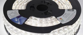
Address strips differ in density - from 30 to 144 LEDs per meter, and are manufactured in different protective versions: IP30, IP65, IP67, IP68. All versions, except IP30, can be used outdoors in the temperature range from -25 to +80°C. Another, more reliable tape - WS2813 is distinguished by the ability to transmit signals further along the chain even through a burnt-out chip.
LED strip WS2812B characteristics
- LED size - 5 x 5 mm
- PWM frequency - 400 Hz
- Data transfer rate - 800 kHz
- Data size - 24 bits per LED
- Supply voltage - 5 Volts
- Consumption at zero brightness - 1 mA per LED
- Consumption at maximum brightness - 60 mA per LED
- Color: RGB, 256 shades per channel, 16 million colors
Characteristics of WS2812B addressable LED strip
The WS2812b addressable LED strip is the pinnacle of strip evolution. Each LED in the strip consists of a regular RGB LED and a controller with three transistor outputs. Thanks to this, it is possible to control the color of any LED and create stunning color and lighting effects. That is why the device is popular, despite its high cost.
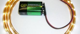
How to check the address tape without Arduino
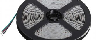
When connecting, pay attention to the direction of the arrows
Many people are interested in how to turn on the address strip without Arduino and check its functionality. If you simply connect power to the tape, nothing will happen—you can’t test the tape without a controller. If you touch the digital input of the address strip, several LEDs may light up due to random interference, which is perceived by the ws2812b LED controllers as commands.
If you don’t have an Arduino board at hand, you can use a special controller to check. As a last resort, just touch the digital wire to understand whether the LEDs on the strip will light up or not. There is no other reliable way to check the operation of the ws2812b strip, so we will next consider managing and programming an addressable LED strip on an Arduino Nano or Uno microcontroller.
What do you need to order for this project?
This is what my package with fifty pieces of diode strip looked like
▸ The first and most important thing is the addressable LEDs. In order to solder fewer wires and diodes than last year, I suggest immediately buying diodes on tape.
Tapes with a density of 30 diodes per meter are ideal. The distance between them on the tape is approximately 3 cm, which means it is best to attach such tapes to the window in 3 cm increments. This will result in a uniform matrix with the correct proportions of the picture.
Based on these data, we calculate the required number of tapes for the order. We buy the most affordable tape WS1218B on a white base with a moisture protection class of IP30 .
We don’t need a more secure and expensive tape; we will attach it indoors. A meter piece of such tape costs 100 rubles.
Considering the large number of ribbons ordered and all kinds of coupons, we will save a lot of money.
Don't skimp on the power supply, buy it with power to spare
▸ To power such a matrix you will need a powerful power supply. You can calculate the power reserve based on the table below.
Provide a minimum of 3A for every 100 diodes. When building a matrix for 1000 diodes, choose a 5V 30A block, or better yet, a 40A block with a margin.
This power adapter will cost from 990 rubles.
Wemos D1 mini and combined time module + card reader
▸ To control the matrix, you will need a board based on the ESP8266 NodeMCU or Wemos D1 mini microcontroller. No Arduino model can handle such a matrix.
NodeMcu board – from 145 rubles.
Wemos D1 mini board – from 85 rub.
▸ Soldering iron SH72 is suitable for soldering components – from RUR 976.
▸ Don’t forget about rosin and tin for soldering - from 270 rubles.
Connecting to Arduino
Direct connection of the LED strip to Arduino is only appropriate when using weak LED diodes. For an LED strip, additional electrical elements must be installed between it and the board.
Via relay
Connect the relay to the Arduino board via digital output. The controlled strip can have one of two states - on or off. If you need to organize control of an RGB strip, you will need three relays.
The current controlled by this device is limited by the power of the coil. If the power is too low, the element will not be able to close large contacts. For the highest powers, use relay assemblies.
Using a bipolar transistor
If you need to increase the current or voltage at the output, connect a bipolar transistor. When choosing it, focus on the load current. The control current does not exceed 20 mA, so add a 1 - 10 kOhm resistor to limit the current through resistance.
Using a field effect transistor
Instead of bipolar transistors, use field-effect transistors (abbreviated as MOS) to control LED strips. The difference between them is related to the control principle: bipolar ones change the current, field ones change the gate voltage. Thanks to this, a small gate current drives a large load (tens of amperes).
Using expansion cards
If you don’t want to use relays and transistors, you can buy entire blocks - expansion boards. These include Wi-Fi, Bluetooth, equalizer, driver, etc., which are required to control loads of different powers and voltages. These can be either single-channel elements, which are suitable for monochrome tapes, or multi-channel (for controlling RGB color tapes).
Softbox operating modes
The softbox can perform its immediate duties: provide soft diffused light with adjustable brightness. Two additional controls allow you to change the color tone and saturation. Those. You can shine any color by specifying it in the HSV color model (HSB - Hue, Saturation, Brightness - tone, saturation, brightness). But is this just mode 1 of 7 possible ones? The full list of modes is as follows:
- Static HSB - Hue, Saturation, Brightness
- Dynamic HSB - tone automatically changes from minimum to maximum value
- Rainbow
- Fireflies
- Rainbow noise
- Cloud noise
- Lava noise
All dynamic effects have the ability to adjust brightness, dynamics and scale.
The principle of operation of a transistor for smooth control of an LED strip
A transistor works like a water faucet, only for electrons. The higher the voltage applied to the base of the bipolar transistor or the drain of the field effect transistor, the lower the resistance in the emitter-collector circuit, the higher the current passing through the load.
Having connected the transistor to the Arduino analog port, we assign it a value from 0 to 255, and change the voltage supplied to the collector or drain from 0 to 5V. The collector-emitter circuit will pass from 0 to 100% of the load reference voltage.
To control an Arduino LED strip, you need to select a transistor of suitable power. The operating current for powering the LED meter is 300-500mA; a power bipolar transistor is suitable for these purposes. For longer lengths, a field effect transistor will be required.
Connection diagram for LED strip to Arduino:
This is interesting: Choosing ceiling chandeliers with a fan
Mechanical assembly
It is better to insulate the edges so as not to shorten the tape onto the body. You need to glue the tape with a zigzag, and not just like that. For a softbox, it is better to use a tape with a white backing, and not with a black one like mine.
It is optimal to place the power lines at about a third of the distance from the center of the matrix. This will reduce the average distance to each LED and reduce energy loss and overheating of the device.
Perhaps I’ll stuff the “brains” and controls inside the power supply. We connect the 230 volt power wire: phase, neutral and protective grounding.
Before turning it on, I recommend checking all the lines again for shorts to the housing.
Setting up the Blynk app
Blynk is an application that can run on Android and IOS mobile operating systems and allows you to use your smartphone to control various devices that support the concept of the Internet of Things (IoT). When using this application, we first need to create a Graphical User Interface (GUI) in it. From this GUI, data will be transferred to the Blynk cloud. On the receiving side we have an Arduino board connected to the computer via a USB cable. Thus, the computer requests this data from the Blynk cloud and then this data is transferred to the Arduino board for further processing.
Creating a new project
After successful installation and registration in the Blynk application, you will see a “New Project” button on its main page. Click it and a new window will open in your application, in which you will need to enter project parameters such as name, board and connection type. For our project, select the “Arduino UNO” board, the connection type “USB” and click on the “Create” button.
After successfully creating a project, you will receive your Authenticate ID by email (with which you registered in the application). Save it - we will need it in the future.
Creating a Graphical User Interface (GUI)
Open the project in the Blynk application, in it click on the “+” icon - after this you will have access to widgets (graphic elements) that you can use in your project. In our case, we will need an RGB Color Picker which is named “zeRGBa”, as shown in the following image.
Installing the widget
After dragging the widget into our project, we need to set its parameters, which will be necessary to transfer color values to the Arduino UNO board.
Click on ZeRGBa, after which a screen with its settings will open (ZeRGBa setting). Set the Output option in it to the “Merge” position, and set the “V2” pin to the position shown in the following figure:
Arduino and addressable LED strip
This project is a simple way to get started, but the ideas it covers can be expanded upon for truly dramatic lighting. With just a few ingredients you can create your own sunrise. If you have an Arduino starter kit, you can use any button or sensor to trigger the LEDs when you enter a room, for example:
Arduino LED strip – Bright ideas.
These ribbons require fewer components to run, and there is some freedom as to exactly what component values you can use. The capacitor in this circuit ensures that the 5v LEDs receive a constant power supply. The resistor ensures that the data signal received from the Arduino is not loaded with all sorts of noise.
You will need:
● LED strip 5v WS2811/12/12B; All three models have built-in chips and work the same.
● 1 x Arduino Uno or similar compatible board;
● 1 x resistor 220-440 Ohm;
● 1 x microFarad 100-1000 capacitor (anything between these two values is fine);
● Layout and installation wires;
● 5V power supply.
Set up the circuit as shown in the figure:
Please note that the capacitor must be in the correct orientation. You can figure out which side attaches to the ground rail by looking for the minus sign (-) on the capacitor body
This time we will power the Arduino using a 5V power supply. This will allow the device to work autonomously
You can figure out which side attaches to the ground rail by looking for the minus sign (-) on the capacitor body. This time we will power the Arduino using a 5V power supply. This will allow the device to operate autonomously.
First, make sure your board can handle 5V before connecting it to the power supply. Almost all boards operate at 5V via USB, but the power pins on some can sometimes skip voltage regulators and turn them into toast.
Additionally, it is recommended to ensure that multiple separate power sources are not connected to the Arduino - disconnect the USB cable whenever using an external power source.
A little theory
If you have absolutely no idea how the LED strip works, it’s worth getting acquainted with the very principle of its operation. Its main element, which produces light, is a semiconductor device consisting of two crystals. The atomic structure of one of them is dominated by negatively charged ions (electrons), while the other is dominated by positive ones (so-called holes). If this crystalline “sandwich” is connected to a galvanic battery, then if the poles coincide – plus to the element with “holes”, and minus to the one where electrons predominate – current will flow through it. It will cause a glow at the junction of materials.
Note that the glow effect only occurs when the pluses and minuses coincide. That is, if you connect an LED to an AC source, it will start blinking. But that's not all. These crystals are quite small - no more than five millimeters in diameter. If you pass a household current of 15 A through them, they will simply burn out. For this reason, LED strips are connected to special power sources that reduce the voltage and rectify it.
The power supply must have a rectifying diode bridge and an RC filter at the input, smoothing out ripples (instability) of the supply voltage. The quality of the power supply depends on this filter. The most reliable and expensive ones use current stabilizers on microcircuits. In simple ones - those same RC filters.
The industry produces LED strips powered by both 24 and 12 volts. The output voltage of the power supply must match this rating.
The electrical circuit of the power supply for LED strips is similar to those used to power lighting lamps of the same type.