There are several versions of Arduino nano boards. There is version 2.X, and there is version 3.0. These versions differ in the microcontroller itself. The younger version of this arduino uses the ATmega168 chip. This chip has a smaller amount of flash memory, non-volatile memory, and a lower clock frequency. Since the price of different versions of Arduino nano is practically the same, we will not consider the youngest of them. Arduino nano v 3.0 is equipped with an ATmega328P microcontroller. Unlike its younger brother, it has twice the amount of non-volatile and flash memory. And it boasts a clock speed of 16 MHz.
Arduino nano has almost the same capabilities as Arduino Uno, despite being half the size. Many hobbyists use this particular board as their main one, since it can be conveniently placed on a solderless breadboard along with other project elements. Yes, and in the final project you can also use this arduino because it is small (42 mm * 19 mm) and has low power consumption.
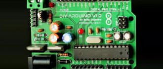
Arduino Nano V3 elements
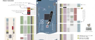
Arduino Nano board pinout
There are pin contacts on both sides of the board, 15 on each side.
Contact assignment:
- 1, 2: work with the UART interface;
- 3, 28: microcontroller reset;
- 4, 29: common wire;
- 5: external interrupt;
- 6: External interrupt/create pulse width modulated signal;
- 7: work with I2C interface / timer-counter 0;
- 8: work with I2C interface / create PWM signal / timer-counter 1;
- 9, 12: creating a PWM signal;
- 10, 11: digital I/O pins, no special functions;
- 13, 14, 15: working with the SPI interface / creating a PWM signal;
- 16: LED connection / work with SPI interface;
- 17: power supply 3.3V;
- 18: reference voltage for ADC;
- 19-26: analog inputs (AP) for ADC;
- 27: 5V power supply;
- 30: VIN 7-12V input signal.
Arduino Nano has 14 digital ports (DP) and 8 AP.
Additional details
In addition to the Arduino board itself, we will also need a number of additional components and it is better to immediately buy them together with the microcontroller. For beginners you can buy additionally:
- the arduino nano board itself
- resistors (220 Ohm and other capacities)
- LEDs
- breadboard (sometimes called breadboards)
- jumper wires
So you should end up with something like this:
Board specifications
| Nutrition | 5 V |
| Input signal | 7-12 V (DC) |
| Number of DP | 14 (6 for PWM) |
| Number of APs | 8 |
| Maximum current DP | 40 mA |
| Flash format memory | 16 / 32 KB |
| RAM | 1 / 2 KB |
| EEPROM format memory | 512 bytes / 1 KB |
| Microcontroller clock frequency | 16 MHz |
| Dimensions | Width - 19 mm, length - 42 mm |
| Weight | 7 g |
A detailed overview of the board's capabilities is provided in the Datasheet - technical documentation. Detailed characteristics and description of AN are also indicated there.
Other pins
- 3.3V pin can be used to power low-power sensors and modules: the maximum current that can be removed from the 3.3V pin is 150 mA, which is enough for any sensors and modules, except perhaps the nrf25L01 radio modules.
- GND pins – power ground, all GNDs are interconnected
- Pin 5V – power supply from a source with a voltage of up to 5.5V (for more details about power supply, see the next lesson)
- Pin Vin – power from a source with a voltage of 7-15V (for more details about power supply, see the next lesson)
- RST – MK reboot. This pin is also displayed on the button
Electric scheme
The most important elements of the Arduino Nano board are the programmer (ISCP connector) and the microcontroller (ATmega328P). It is necessary for everyone who is going to work with this board to know their structural, circuit diagrams and the purpose of contacts.
ISCP circuit "Arduino Nano"
ISCP connector (or SPI) is a programmer through which the sketch (code for the board’s microcontroller) is loaded into the ATmega328P. It has 6 contacts. The hole of the first of them is made in the shape of a square for ease of reference.
Connector pinout:
- MISO: Master input, slave output when transmitting data.
- +VCC: supply voltage.
- SCK: serial clock signal.
- MOSI: master output, slave input when transmitting data.
- Reset: reset.
- GND: common wire.
Schematic diagram of the board controller
The board controller is ATmega328P. The core of the chip is the CPU, to which there are 2 buses (data bus and input/output data bus), control elements (for example, the Reset pin, responsible for resetting the microcontroller) and memory.
Types of memory in the controller:
- SRAM;
- Flash;
- EEPROM
The following elements go to the data bus:
- Watchdog timer.
- ADC.
- External interrupt.
- The first and second timer-counters.
- USART and I2C (Atmel calls this interface TWI).
The following are connected to the data input/output bus:
- I/O ports.
- Zero timer-counter.
- SPI interface.
The controller can be implemented in both MLF and PDIP packages. The Arduino Nano has an MLF version of the microcontroller installed.
Buying Arduino
Arduino is increasingly taking over our world. Is it worth buying expensive devices when many things for the home can be done with your own hands? We have already managed to make a working laptop based on Arduino and Raspberry. Taking all this into account, microcontrollers are gaining more and more popularity.
Let's dwell on the cost of the board for our master class. This board is very miniature and is a full-fledged analogue of many other boards, and that is why we chose Nano for this master class.
You can buy Nano in many online stores. So, for example, the cost of Arduino Nano 3.0 at the end of March 2022 in different stores was:
- iarduino.ru — 525 rubles
- amperka.ru — 1490 rubles
- duino.ru — 325 rubles
- smartelements.ru — 590 rubles
But even this is not the limit; the cost of full-fledged analogues on the well-known aliexpress.com can be in the range of 150-200 rubles. For those who decide to make a purchase on AliExpress, you can read our small step-by-step instructions.
I/O ports and power
I/O ports include:
- digital connectors;
- analog connectors;
- connectors outputting a PWM signal;
- connectors for working with ADC, I2C (TWI), SPI, UART.
To work with each interface in the C language for Arduino, a separate library is provided, which makes the work easier for the programmer who writes the code.
Power can be connected to the Nano model board in 3 ways:
- Via mini-USB connector. This method is convenient because the developer does not need to supply additional current to the board. Such a power supply supports systems that allow you to regulate the value of the input current.
- Through unregulated sources of 6-20 V.
- Via regulated 5V power supply.
The Arduino Nano board is programmed in such a way that if power is connected to all available pins, the microcontroller will select the signal with the highest voltage value and block the remaining power pins.
External power supply
Power through unregulated 6-20 V sources is provided by connecting the signal source block to pin 30 and the common wire, respectively.
The method of connecting power through a regulated 5 V source is the most popular among developers. To use it, you must additionally include a converter with an output voltage of 5 V in the circuit, and energy conversion always entails additional losses and deterioration in signal quality. Connection of such a source is provided through pin 27 and a common wire.
You can connect a signal source to the microcontroller that exceeds the permissible amplitude. But then it must be connected to the board through a limiting resistor so that the diodes can limit the signal in amplitude and not be punctured, otherwise the controller on the board will burn out.
Lock Bits (Pro)
Lock-bits allow you to control access to microcontroller memory, which is usually used to protect the device from copying. Lock bits are again collected into a configuration lock byte, which contains: BOOTLOCK01, BOOTLOCK02, BOOTLOCK11, BOOTLOCK12, LOCKBIT1, LOCKBIT2 (for ATmega328). You can use this lock bit calculator. BOOTLOCK bits allow you to prohibit the MK itself from writing (self-programming) into flash memory (program area and bootloader area)
But the LOCKBIT allow you to prohibit writing and reading flash and EEPROM memory from the outside, using a programmer, i.e. Completely protect the firmware from downloading and copying:
Thus, by enabling LOCKBIT1 (lock byte will be 0x3E ) we will prohibit external writing to Flash and EEPROM memory, i.e. using an ISP programmer, and by enabling LOCKBIT1 and LOCKBIT2 (lock byte: 0x3C ) we will completely block at the same time reading data from the microcontroller memory. I repeat, everything described above applies to the ATmega328p; for other MK models, read the corresponding datasheets.
Firmware and memory Arduino v3 0 CH340G
The standard version of the Arduino Nano board, running on the ATmega328P chip, can be flashed exclusively through a programmer with an SPI interface.
In addition, the AN model is produced, on which the CH340G chip is additionally installed. The advantage of this assembly is that the board can be flashed without connecting an SPI programmer via a USB port. This can be done with the built-in bootloader and USB-COM converter.
If necessary, such a Nano model can also be flashed via the SPI interface.
To download firmware via mini-USB, you will need:
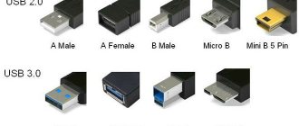
- Connect the board to the PC via USB. The system will detect the device as USB 2.0 SERIAL.
- Download and install the CH340G driver.
As soon as the driver is installed, the system will detect the board correctly and it can be flashed through the programmer. The ON LED on the board will light up and the LED will blink.
Types of memory
ATmega328P supports 3 types of memory:
- Flash. It acts as a permanent storage device.
- RAM.
- EEPROM This memory is also a read-only memory, but it can be reprogrammed.
The microcontroller from Atmel has 32 KB of Flash memory (30 KB free, since 2 KB is occupied by the bootloader), 2 KB of RAM and 1 KB of EEPROM.
Fuses (Pro)
Fuses (fuse bits) are low-level microcontroller settings that are stored in a special location in memory and can only be changed using an ISP programmer. These are settings such as selecting a clock source, the size of the memory area for the bootloader, setting the voltage cutoff, etc. Fuse bits are collected 8 pieces into bytes (so-called configuration bytes), like a typical register of an AVR microcontroller. There can be several such bytes; they are called low fuses, high fuses, extended fuses. To configure the bytes, it is recommended to use a fuse calculator (for example, this one), in which you simply check the required bits, and the output is a ready-made byte in hex form. Let's look at the ATmega328p as an example:
An important point: in AVR the bits are inverted , that is, 1 is off, 0 is on. By placing checkmarks in the calculator, we form a byte; if the checkmark is checked, the bit is turned on, but in the resulting byte the included bits are zeros. This is worth thinking about when manually compiling a fuse byte; when using a calculator, you don’t even have to think about it. What do the bits allow you to configure?
- CKSEL0 – CKSEL3 – selection of clock source and frequency (check in the datasheet for your MK which configuration is responsible for what)
- SUT0 – SUT1 – MK start delay after reboot
- CKOUT – duplication of clocking on one of the pins (see which one in the datasheet)
- CKDIV8 – divides the clock frequency by 8
- BOOTRST – if enabled, the MK starts from the bootloader
- BOOTSZ0 – BOOTSZ1 – sets the size of the bootloader sector
- EESAVE – protects EEPROM from erasing while performing a full chip wipe
- WDTON – if enabled, Watchdog will be forcibly enabled without the ability to disable
- SPIEN is a dangerous bit; when it is turned off, the ability to flash firmware via ISP is lost, including the ability to turn off this bit *
- DWEN – turn on/off the DebugWire debugging interface. On other models there is both JTAG and its bit - JTAGEN
- BODLEVEL0 – BODLEVEL3 – voltage control setting (MK will reset when it drops below the set voltage)
* – firmware can be updated using a high-voltage programmer
Board elements
Arduino Nano consists of many elements, including:
- microcircuits;
- passive elements (resistors, capacitors, diodes);
- connectors;
- regulators.
FT232R board chip
The chip allows you to connect the board via USB. The chip installed in the AN cannot work directly with the USB interface, so the FT232R converts it to a UART interface.
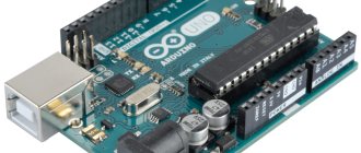
The heart of the platform is the ATmega328P microcontroller
ATmega328P is the main control element of the board. A sketch written by the programmer is loaded into it, and the controller sends commands to various elements of the board. For example, a microcontroller causes diodes to blink, relays to switch, and a piezoelectric element to make sounds.
LED indication
There are 4 LEDs built into the board, each of which has its own purpose:
- The RX and TX LEDs blink when data is being transferred via the UART.
- The L-diode lights up when a high signal level is applied to it, and turns off when the signal level is low.
- The ON LED lights up when there is power on the board.
Additionally, almost any pin of the microcontroller can be connected to other LEDs, 7-segment indicators or even displays.
Mini-USB connector
Using the mini-USB connector, the board can be connected to a personal computer. The AN can also receive power from external sources through this interface.
Linear Buck Voltage Regulator 5V
The LM1117MPX-5.0 microcircuit is used as a regulator. It converts the AN power signal into a power signal for the ATmega microcontroller and other logic elements that do not support power supplies greater than 5 V. For example, transistor-transistor logic (TTL) elements are powered by a signal of this magnitude.
ICSP connector for ATmega328
This interface allows you to download firmware to the microcontroller in a standard way. A special cable is connected at one end to the programmer connected to the PC, and at the other end to the ICSP connector.
What is the I2C protocol and how does it work
The term IIC stands for “Inter Integrated Circuits” and is often referred to as I2C or even TWI (2-wire interface protocol), but in all cases the same protocol is hidden behind these designations. I2C is a synchronous communication protocol - this means that both devices that exchange information using this protocol must use a common synchronization signal. Since this protocol uses only 2 lines (wires), a synchronization signal must be transmitted along one of them, and useful information along the other.
The I2C protocol was first proposed by Phillips. The protocol in its simplest case connects 2 devices using 2 lines, one of the devices must be a master and the other a slave. Communication is only possible between master and slave. The advantage of the I2C protocol (interface) is that several slaves can be connected to one master.
The communication diagram using the I2C protocol is shown in the following figure.
Purpose of lines of this interface:
- Serial Clock (SCL) : it transmits the general synchronization signal generated by the master device;
- Serial Data (SDA) : It transfers data between master and slave.
At any time, only the master can initiate the data exchange process. Since this protocol allows multiple slaves, the master must access them using different addresses. That is, only a slave with a given (specified) address must respond to the master’s signal, and all other slaves must “remain silent” at this time. Thus, we can use the same bus (line) to exchange data with several devices.
The voltage levels for transmitted signals in the I2C interface are not strictly defined. In this regard, I2C is quite flexible, that is, if a device is powered by a voltage of 5v, it can use the 5v level to communicate using the I2C protocol, and if the device is powered by a voltage of 3.3v, then it can use the 3v level to communicate using the I2C protocol . But what should you do if, using this protocol, you need to connect devices operating on different supply voltages? In this case, voltage shifters are used.
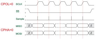
There are several conditions for data transmission in the I2C protocol. Transmission initialization begins with a drop in the SDA line, which is defined as the 'START' condition in the diagram below. As can be seen from this figure, while the level is falling on the SDA line, at the same time on the SCL line the master maintains the voltage high.
That is, as follows from the figure, a drop in the level on the SDA line is a hardware trigger for the condition for the start of transmission. After this, all devices on this bus switch to listening mode.
Likewise, a rise on the SDA line stops data transfer, which is referred to in the diagram as a 'STOP' condition. At the same time, the master on the SCL line maintains a high voltage level (high).
The following figure shows the structure of the slave address in the I2C protocol.
The R/W bit indicates the direction of transmission of the following bytes; if it is set to HIGH, this means that the slave will transmit, and if it is set to low, this means that the master will transmit.
Each bit is transmitted in its own time cycle, that is, it takes 8 time cycles to transmit a byte of information. After each byte transmitted or received, the 9th time cycle is used to confirm/not acknowledge (ACK/NACK) the receipt of information. This acknowledgment bit (ACK bit) is generated by either the slave or the master, depending on the situation. To confirm the receipt of information (ACK) on the SDA line, the master or slave is set to a low level (low) in the 9th time cycle, otherwise there is no acknowledgment of receipt of information (NACK).
The following figure shows the structure of a transmitted message in the I2C protocol.
Features of driver installation
When installing drivers for Arduino Nano on Windows OS, the system will detect the necessary software automatically if the installation file from the official Arduino website was used.
If the drivers were not detected and installed by the system, you must:
- Open the control panel.
- Go to the "System and Security" section.
- Go to the “System” tab.
- Open Device Manager.
- Open a tab with COM and LPT ports.
- If the tab does not have an FT232R USB UART port or a section with COM and LPT connectors, go to the “Other devices” tab and go to the “Unknown device” section.
- Right click on FT232R USB UART.
- Select "Update Drivers".
- Click “Search for drivers on your computer.”
- Select FTDI USB Drivers from the Arduino Drivers folder.
If all steps are completed correctly, the system will complete the installation of the software for AN.
Communication Interfaces
Arduino Nano supports I2C interface for communication with various devices and peripherals. One common application is communicating with a display via the I2C bus. Thanks to special technology, you can display sets of characters and data on the display using only 2 pins, in Nano these are pins D4 SDA) and D5 (SCL).
The official website has a special library for working with it. When writing programs, do not forget to include it with the directive:
#include SPI.h
Now you can organize a communication system.
Launching Arduino Nano
To start working with the board, you need to connect it via USB to your PC. The power signal will come through the same port. As soon as it is connected to the board, the blue indicator LED will light up (in the v.2.x model it is located at the bottom of the board, in the v.3.x model it is at the top).
Arduino setup
To configure the board to work with the written code, you need in the programming environment:
- go to Tools;
- go to Board;
- select Arduino Duemilanove or Nano w/ *microcontroller model* (for v.2.x - ATmega168, for v.3.x - ATmega328);
- go to Tools;
- go to Serial Port;
- click Upload.
After pressing the Upload button, the microcontroller will be reset and a new sketch will be uploaded.
If any problems arise during the firmware, you need to go to the “Troubleshooting” section and study methods for solving them.
To summarize
Now, in essence: sensors, there are a bunch of them, you can measure, well, just everything that is measured at all. Electronics: voltage, current, resistance, AC operation, fields. Microclimate parameters: temperature, humidity, pressure, gas content, wind speed, illumination, whatever. There are also a lot of interesting modules: Bluetooth, cellular communications, GPS, displays of various types and sizes, presence sensors, both IR and microwave, modules for wireless communication of Arduinos and much more.
You can control absolutely any piece of hardware that performs its function simply when power is applied: a light bulb, an LED strip, an electric heater, a motor or any electric drive, an electromagnet, a pusher solenoid, and this is all with any supply voltage. But here you need to understand something: Arduino (more precisely, a microcontroller) is a logical device, that is, in an amicable way, it should only give commands to other devices, or receive them from them. What I mean is that neither light bulbs, nor motors, nor heaters, nor worse, work directly from the Arduino. Maximum - LED. With this understanding, we move on. In order for the Arduino to turn on or off (supply power) to another device, you need an intermediary device, such as a relay or transistor. Arduino controls the relay, and the relay, in turn, turns on any desired load with any supply voltage and all that, we’ll talk about this in more detail separately.
As the essence of everything written above, Arduino’s possibilities for connecting and controlling various pieces of hardware are almost limitless; you can implement any idea, even the craziest one. Sensors measure something, actuators control something, at the same time data is sent somewhere, something is displayed on the display and controlled using buttons. Romance!
In my catalog of links to Arduino components you can find almost all existing sensors, modules and other hardware for Arduino, and almost everyone has a link to an article with an example and a library. Use it!
Programming Methods
You can program the board using either handwritten or graphical code.
The graphical programming method involves using the ArduBlock plugin (supports Russian language), which is built into the Arduino IDE. The program is initially designed in the form of a block diagram, and then automatically converted into Arduino IDE code (suitable for novice programmers).
To install the Arduino IDE plugin:
- Install the Arduino IDE programming environment (available on the official Arduino website).
- Download the ArduBlock plugin from the developers' website.
- Rename the downloaded file to ardublock-all.
- Create Arduino folders in the Documents section, then tools, ArduBlock and tool.
- Move the downloaded and renamed file to the tool folder.
To work with this plugin, you need:
- Launch the programming environment.
- Go to the “Tools” tab.
- Click on the ArduBlock section.
By programming the board we also mean ways to load the firmware into the microcontroller. The most popular method is in-circuit programming (ISP), in which the ATmega is flashed through a programmer connected via an SPI interface to the board and via a USB cable to the PC. Using the same method, you can reflash AN.
Boards using the CH340 chip can be flashed via USB.
You can check the functionality of the code in programs such as:
- Proteus;
- AutoCAD 123D;
- Tinkercad.
All utilities have a convenient graphical interface and a large set of components. You can design printed circuit boards in Proteus and AutoCAD. To work with Tinkercad, you only need a browser and a stable Internet connection, since this software runs online.
Important Pages
- GyverKIT kit - a large Arduino starter kit of my design, sold in Russia
- Catalog of links to cheap Arduins, sensors, modules and other hardware from AliExpress from trusted sellers
- A selection of libraries for Arduino, the most interesting and useful, official and not so
- Complete documentation on the Arduino language, all built-in functions and macros, all available data types
- A collection of useful algorithms for writing sketches: code structure, timers, filters, data parsing
- Video lessons on Arduino programming from the “Arduino Engineer's Notes ” channel are some of the most detailed in RuNet
- Support the author for his work on the lessons
- Feedback - report an error in the lesson or suggest an addition to the text ( [email protected] )
5 / 5 ( 16 votes)
Example projects with Arduino Nano
It is convenient to implement projects on AN due to the presence of libraries that simplify writing code.
Connecting LEDs to Arduino Nano
You can power the LED diode, for example, using pin 13 through a 220 Ohm limiting resistor. To blink this diode, you should write the following code:
| 1 2 3 4 5 6 7 8 9 10 | void setup() { // initialization of code elements (analogous to int main() in C) pinMode(13, OUTPUT); // declare pin 13 as an output } void loop() { // infinite loop (analogous to while (1) in C) digitalWrite(13, HIGH); // turn on the LED delay(1000); // ensure blinking at a frequency of 1 Hz digitalWrite(13, LOW); // turn off the LED delay(1000); // ensure blinking at a frequency of 1 Hz } |
void setup() { // initialization of code elements (analogous to int main() in C) pinMode(13, OUTPUT);
// declare pin 13 as an output } void loop() { // infinite loop (analogous to while (1) in C) digitalWrite(13, HIGH); // turn on the LED delay(1000); // ensure blinking at a frequency of 1 Hz digitalWrite(13, LOW); // turn off the LED delay(1000); //provide blinking with a frequency of 1 Hz } To create a pixel image, where a pixel is 1 diode, a WS2812 address strip is used.
Connecting LCD 1602 to Arduino Nano
The LCD 1602 is a monochrome programmable display. To connect it to the board you need to write the following sketch:
| 1 2 3 4 5 6 7 8 9 10 11 12 | #include LiquidCrystal lcd(12, 11, 5, 4, 3, 2); void setup(){ lcd.init(); // initializing the screen lcd.backlight(); // activate the backlight lcd.setCursor(0,0); // placing the cursor at the beginning of the first line lcd.print("text"); // typing text on the first line lcd.setCursor(0,1); // placing the cursor at the beginning of the second line lcd.print("text"); // typing text on the second line } |
#include LiquidCrystal lcd(12, 11, 5, 4, 3, 2); void setup(){ lcd.init(); // initializing the screen lcd.backlight(); // activate the backlight lcd.setCursor(0,0); // placing the cursor at the beginning of the first line lcd.print("text"); // typing text on the first line lcd.setCursor(0,1); // placing the cursor at the beginning of the second line lcd.print("text"); // typing text on the second line }
Connecting NRF24L01 to Arduino Nano
NRF24L01 is a radio module that is often used to create the Internet of Things. It is installed on the board as follows:
| Module pin | Pinout boards |
| GND | GND |
| VCC | 3.3 V |
| C.E. | D9 |
| CSN | D10 |
| SCK | D13 |
| MOSI | D11 |
| MISO | D12 |
| IRQ | Doesn't connect |
Sketch explanation for the master
The bulk of the code for both the master and slave devices is what I call blink logic code. To flash LED 13 on Arduino we have to do the following:
- Let's add global variables byte i2c_rcv, int time_start, stat_LED and byte value_pot at the top of our sketch
- Initialize the values of global variables inside the setup() function
- Initialize Arduino pin 13 as output pin inside setup() using pinMode()
- Let's add blinking logic code inside the loop() function
Wire Library
To use Arduino's built-in I2C interface we will use the Wire .
This library comes standard with the Arduino IDE. Like other Arduino libraries, the Wire library has ready-made I2C functions to make coding easier for us.
To use the Wire library's features, we must add it to our sketch first. In the sketch above, we have the following line at the top:
#include
After enabling the library, we can use the library's built-in functions.
The first thing to do is connect the device to the I2C bus. The syntax for this is Wire.begin(address). The address is optional for master devices. So, for the Arduino master sketch, we simply add the code Wire.begin(); inside setup().
Now we move on to the loop() loop. Our code will make the Arduino read the value of the potentiometer connected to pin A0 and store it in the value_pot variable.
Sending data
After storing the value from pin A0 into the value_pot variable, we can send the value via I2C. Sending data over I2C includes three functions:
- Wire.beginTransmission()
- Wire.write()
- Wire.endTransmission()
Wire.beginTransmission()
We initiate a send command by first informing the devices on the bus that we will be sending data.
To do this, we call the Wire.beginTransmission(address) function. Address is the I2C address of the slave device that will receive the data. This function does two things:
- It informs the bus that we will send data.
- It informs the intended recipient that the data is ready to be received.
Wire.write()
And then we will send the value of the variable value_to_send using the Wire.write(value) function.
Wire.endTransmission()
After sending the data, we need to free up the network to allow other devices to communicate over the network. This is done using the Wire.endTransmission() function.
Our master device must also receive the potentiometer position from the slave device. We do this using Wire.requestFrom(), Wire.available() and Wire.read().
Wire.requestFrom()
The full syntax for requesting data from a slave is Wire.requestFrom(address, quantity).
Address is the I2C address of the slave device from which we need to receive data, and quantity is the number of bytes we need. For our project, the slave address is 0x08 and we need one byte.
Inside loop() we use Wire.requestFrom(0x08, 1); to request one byte of data from the slave 0x08 .
After issuing the Wire.requestFrom(0x08, 1) command, it must be followed by a read command to obtain a response from the I2C bus.
Write.available()
First we check if there is data on the bus. This is done using the Write.available() function inside an if() conditional statement. The Write.available() function returns the number of bytes waiting to be read.
Wire.read();
To get the available data, we use the Wire.read() function and store the return value in the i2c_rcv variable. Each Wire.read() function call receives only one byte of data from the I2C bus.
Popular shields for Arduino Nano
A shield is called an add-on board.
Popular shields for the Nano model include:
- Nano Uno Shield: Extends AN to Uno variant;
- Arduino Motor: allows you to connect motors to the board (for example, using the DRV8825 driver you can connect a stepper motor and assemble your own car);
- Arduino Sensor: shield for connecting any modules (for example, a driver whose control object is a mechanical arm).