For safe operation of various electrical installations, grounding is required. Natural grounding is one of the common measures. It can be used as steel reinforcement, which is part of the concrete structure. In addition, other metal devices located in the ground are applicable. Plumbing communications and cables are suitable; less commonly, above-ground structures, such as metal pipes or rails, can be used for the ground electrode.
Types of grounding systems
The following types of grounding are suitable for a private house and apartment:
- TN;
- IT;
- TT.
The first and most common TN system has subtypes - S and C S. In general, to decipher the abbreviations you need to understand several points.
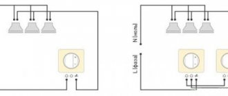
- By default, the first letter t indicates the operating principle of the power source.
- The second letter - N, T or I - indicates the principle of grounding and protection of open tap elements. T is prescribed if the circuit is grounded, N - if grounding is carried out by connecting to the neutral, and I - when the electrical equipment does not have electrical contacts, that is, the outlet is isolated. In the picture below you will see the grounding symbol and the corresponding diagram.
- The current State Standards have the concept of a neutral grounding conductor. It is relevant for systems with voltages up to 1 kV. The following are distinguished: earth (PE), neutral ground conductor (N) and connection of earth with zero (PEN).
Why is it necessary to combine ground loops?
When lightning strikes a lightning rod, a short electrical impulse with a voltage of up to hundreds of kilovolts occurs in the latter. At such a high voltage, a breakdown of the gap between the lightning rod and the metal structures of the house, including electrical cables, may occur. The consequence of this will be the emergence of uncontrolled currents, which can lead to fire, failure of electronics and even destruction of infrastructure elements (for example, plastic water pipes). Experienced electricians say: “Give lightning a way, otherwise it will find it on its own.” This is why electrical grounding is mandatory.
For the same reason, the PUE recommends electrically combining not only the groundings located in the same building, but also the groundings of geographically close objects. This concept refers to objects whose groundings are so close that there is no zone of zero potential between them. The combination of several groundings into one is carried out, in accordance with the standards of PUE-7, clause 1.7.55, by connecting the grounding conductors with electrical conductors in the amount of at least two pieces. Moreover, conductors can be either natural (for example, metal elements of a building’s structure) or artificial (wires, rigid busbars, etc.).
What is electrolytic grounding?
Electrolytic grounding is a ready-made device that is used in rocky, sandy and permafrost soils. The kit includes a steel electrode, service well, filler, clamp and waterproofing tape. Where is electrolytic grounding used? The scope of application of the device is different. As a rule, it is used in places where it is not possible to install a grounding electrode to a depth of one meter. And also on soils that have high resistivity.
What does the system consist of?
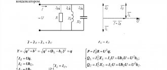
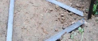
The main element in the device is considered to be a hollow electrode, which has the shape of an L-shaped tube (in the figure it is marked with the number 1).
It is installed in the ground to a depth of one meter (soil thawing zone) and filled with a special mixture that includes mineral salts. 2 is a special well that makes work easier. 3 – clamp with which the electrode and grounding conductor are connected. 4 – waterproofing tape, which protects against moisture getting to the grounding and prevents corrosion.
The photo clearly shows what the ground electrode looks like:
Electrical ground connection
A circuit with several grounds connected electrically ensures that different, sometimes conflicting, requirements for grounding devices are met. According to the PUE, grounding, like many other metal elements of the building, as well as equipment installed in it, must be connected by a potential equalization system. Potential equalization refers to the electrical connection of conductive parts to achieve equal potential. There are main and additional potential equalization systems. Grounding connections are connected to the main potential equalization system, that is, they are connected to each other through the main grounding bus. The wires connecting the grounding to this bus must be connected according to the radial principle, that is, one branch from the specified bus goes to only one ground.
In order to ensure safe operation of the entire system, it is very important to use the most reliable connection between the grounding and the main grounding bus, which will not be destroyed by lightning. To do this, you need to comply with the standards of PUE and GOST R 50571.5.54-2013 “Low-voltage electrical installations. Part 5-54. Grounding devices, protective conductors and protective potential equalization conductors” regarding the cross-section of the potential equalization system wires and their connections to each other.
However, even a very high-quality potential equalization system cannot guarantee the absence of voltage surges in the network when lightning strikes a building. Therefore, along with well-designed grounding loops, surge noise protection devices (SPDs) will save you from problems. Such protection is multi-stage and selective in nature. That is, a set of surge protection devices must be installed at the facility, the selection of elements of which is not an easy task even for an experienced specialist. Fortunately, ready-made SPD kits are available for typical applications.
What is a ground electrode and what can be used as a ground electrode?
What is a ground electrode?
GROUNDING LEADER - a conductive part (or a set of interconnected conductive parts) that is in contact with the ground directly or through an intermediate conductive medium.
What can a grounding conductor be made from?
1.7.109. The following can be used as natural ground electrodes: 1) metal and reinforced concrete structures of buildings and structures in contact with the ground, including reinforced concrete foundations of buildings and structures that have protective waterproofing coatings in non-aggressive, slightly aggressive and moderately aggressive environments; 2) metal water pipes laid in the ground; 3) casing pipes of boreholes; 4) metal sheet piles of hydraulic structures, water conduits, embedded parts of valves, etc.; 5) rail tracks of main non-electrified railways and access roads if there is a deliberate arrangement of jumpers between the rails; 6) other metal structures and structures located in the ground; 7) metal shells of armored cables laid in the ground. Cable sheaths can serve as the only grounding conductors when there are at least two cables. Aluminum cable sheaths are not allowed to be used as grounding conductors.
What cannot be used as a grounding conductor?
1.7.110. It is not allowed to use pipelines of flammable liquids, flammable or explosive gases and mixtures, and sewerage and central heating pipelines as grounding conductors. The specified restrictions do not exclude the need to connect such pipelines to a grounding device for the purpose of equalizing potentials in accordance with 1.7.82. Reinforced concrete structures of buildings and structures with prestressed reinforcement should not be used as grounding conductors, however, this restriction does not apply to overhead line supports and outdoor switchgear support structures. The possibility of using natural grounding conductors based on the density of currents flowing through them, the need to weld reinforcing bars of reinforced concrete foundations and structures, welding anchor bolts of steel columns to reinforcing bars of reinforced concrete foundations, as well as the possibility of using foundations in highly aggressive environments must be determined by calculation.
Requirements for artificial grounding conductors?
1.7.111. Artificial grounding conductors can be made of black or galvanized steel or copper. Artificial grounding conductors should not be painted. 1.7.112. The cross-section of horizontal grounding conductors for electrical installations with voltages above 1 kV should be selected according to the condition of thermal resistance at a permissible heating temperature of 400 °C (short-term heating corresponding to the duration of the protection and tripping of the circuit breaker). In case of danger of corrosion of grounding devices, one of the following measures should be taken: increase the cross-sections of grounding conductors and grounding conductors, taking into account their estimated service life; use galvanized or copper grounding conductors and grounding conductors. In this case, one should take into account the possible increase in the resistance of grounding devices due to corrosion. Trenches for horizontal grounding conductors must be filled with homogeneous soil that does not contain crushed stone and construction waste. Grounding electrodes should not be located (used) in places where the ground is dried out by the heat of pipelines, etc.
Why is it necessary to combine ground loops?
When lightning strikes a lightning rod, a short electrical impulse with a voltage of up to hundreds of kilovolts occurs in the latter. At such a high voltage, a breakdown of the gap between the lightning rod and the metal structures of the house, including electrical cables, may occur. The consequence of this will be the emergence of uncontrolled currents, which can lead to fire, failure of electronics and even destruction of infrastructure elements (for example, plastic water pipes). Experienced electricians say: “Give lightning a way, otherwise it will find it on its own.” This is why electrical grounding is mandatory.
For the same reason, the PUE recommends electrically combining not only the groundings located in the same building, but also the groundings of geographically close objects. This concept refers to objects whose groundings are so close that there is no zone of zero potential between them. The combination of several groundings into one is carried out, in accordance with the standards of PUE-7, clause 1.7.55, by connecting the grounding conductors with electrical conductors in the amount of at least two pieces. Moreover, conductors can be either natural (for example, metal elements of a building’s structure) or artificial (wires, rigid busbars, etc.).
Types of grounding
In the classification of types of grounding there are two main types:
There are several subgroups: radio grounding, measuring, instrumental, control.
There is a certain category of electrical installations that will not work unless they are grounded. That is, the main purpose of constructing a grounding system is not to ensure operational safety, but to ensure the operation itself. Therefore, in this article we will not be interested in this species.
But this type is specially arranged to ensure the safety of electrical installations. It is divided into three categories depending on its purpose:
- Lightning protection.
- Protection against surge voltage (overload of current consumption line or short circuit).
- Protection of the electrical network from electromagnetic interference (most often this type of interference is generated from nearby operating electrical equipment).
We are interested in pulse overvoltage. The purpose of this type of grounding is the safety of operating personnel and the installation itself in the event of an accident or equipment breakdown. Typically, such a breakdown inside an electrical unit is a short circuit of the electrical circuit wire to the device body. The short circuit can occur directly or through any other conductor, for example, through water. A person who touches the installation body is exposed to electric current, because he becomes its conductor into the ground. In fact, it itself becomes part of the ground loop.
Grounding diagram in a private house
That is why, in order to eliminate such situations, the housing is grounded to a circuit located in the ground. At the same time, the activation of the grounding circuit is an impetus for the system of automatic machines, which immediately turn off the power supply to the equipment. All this is located in special power and distribution boards.
Ground resistance
There is such a term as resistance to current flow. For ordinary people it will be easier to perceive it as resistance to grounding. The whole point of this term is that the grounding circuit must work correctly within certain parameters. So resistance is the main one.
The optimal option for this value is zero. That is, it is best to use materials for assembling the circuit that have the highest electrical conductivity. Of course, there is no way to achieve the ideal, so try to choose those with the lowest resistance. These include all metals.
There are special coefficients that are used to determine the resistance of a grounding loop operated under different conditions. Eg:
in private housing construction, where networks of 220 and 380 volts (6 and 10 kV) are used, it is necessary to install a circuit with a resistance of 30 Ohms.
Attention! If a grounding circuit is used through the neutral of the transformer, then the resistance of the grounding circuit should be no more than 4 Ohms
- the installed gas pipeline system entering the house must be grounded with a 10 ohm circuit.
- lightning protection must have a resistance of no more than 10 ohms.
- Telecommunications equipment is grounded using a 2 or 4 ohm loop.
- Substations from 10 kV to 110 kV – 0.5 Ohm.
That is, it turns out that the greater the current power inside the equipment or devices, the lower the resistance should be.
Electrical ground connection
A circuit with several grounds connected electrically ensures that different, sometimes conflicting, requirements for grounding devices are met. According to the PUE, grounding, like many other metal elements of the building, as well as equipment installed in it, must be connected by a potential equalization system. Potential equalization refers to the electrical connection of conductive parts to achieve equal potential. There are main and additional potential equalization systems. Grounding connections are connected to the main potential equalization system, that is, they are connected to each other through the main grounding bus. The wires connecting the grounding to this bus must be connected according to the radial principle, that is, one branch from the specified bus goes to only one ground.
In order to ensure safe operation of the entire system, it is very important to use the most reliable connection between the grounding and the main grounding bus, which will not be destroyed by lightning. To do this, you need to comply with the standards of PUE and GOST R 50571.5.54-2013 “Low-voltage electrical installations. Part 5-54. Grounding devices, protective conductors and protective potential equalization conductors” regarding the cross-section of the potential equalization system wires and their connections to each other.
However, even a very high-quality potential equalization system cannot guarantee the absence of voltage surges in the network when lightning strikes a building. Therefore, along with well-designed grounding loops, surge noise protection devices (SPDs) will save you from problems. Such protection is multi-stage and selective in nature. That is, a set of surge protection devices must be installed at the facility, the selection of elements of which is not an easy task even for an experienced specialist. Fortunately, ready-made SPD kits are available for typical applications.
Operating conditions of ground electrodes
Grounding switches must be used in the conditions for which they are intended, depending on the type used. Maintenance and repairs must be carried out in accordance with the requirements of the manufacturer's operating manual and regulatory documents.
The specified work must be carried out with the involvement of trained and certified personnel, in compliance with the provided permit system.
Before connecting the equipment to the network, the following checks must be performed:
- cleanliness and integrity of insulators;
- tightness of threaded connections;
- presence of lubricant in the relevant components;
- sufficient contact pressure.
The proper operation of the device is first checked by performing several control turns on and off.
Maintenance involves regular inspections of its components, lubrication of rubbing parts, monitoring the condition of contacts, cleaning contacts and other elements. The frequency of maintenance is determined by the conditions and intensity of operation, but must be carried out at least once a year.
Why are natural grounding agents better than artificial ones?
Natural grounding conductors can be used if they are capable of meeting all the requirements for grounding structures.
Artificial grounding conductors should be used when it is necessary to significantly reduce the currents that will flow into the ground through natural grounding conductors.
This means that in most cases, you can only use natural grounding electrodes without resorting to artificial ones. With this step, you can significantly reduce the amount of materials required for the construction of grounding. In addition, financial and labor costs will be reduced, and the operation of the grounding device will be much simpler than when using artificial grounding.
Performing calculations
At the design stage of the ground electrode, it is necessary to select its parameters so that the resistance of the device is within acceptable limits. To do this, a series of calculations are performed.
Soil resistance
The resistance to charge spreading for a single rod is calculated by the formula:
Ro = (Peq/2π*L) *{ln(2L/d) + 0.5 ln((4T + L)/(4T – L)}
If the electrode is placed in heterogeneous soil (2-layer), the resistance is calculated using the formula:
Peq = (Ψ*P1*P2*L)/( P1(L – H + tg) + P2(H – tg)), where
- Ψ – coefficient taking into account seasonality;
- P1 and P2 – specific resistivity of the first and second layers of soil, Ohm/m;
- H – thickness of the top layer, m;
- T – depth of immersion of rods;
- Tg – depth of the vertical pin (distance from the top of the ground electrode to the surface of the earth).
Dimensions and distances for ground electrodes
The minimum length of the rod is 2.5 m. If this condition is met, the base of the electrode with a 100% guarantee will be below the freezing mark of the soil, where acceptable resistance to charge spreading is maintained all year round.
The method for calculating the number of rods depends on what the ground electrode consists of.
If only from vertical electrodes, use the formula:
No = Ro *Ψ/Rн, where
Rн – resistance to spreading recommended by standards.
If the structure has horizontal elements, the number of rods is equal to:
N = Ro/( Rв*ηв), where
ηв – grounding conductor utilization coefficient, taking into account the mutual influence of the electrodes on each other.
In a linear design it is higher, so the calculation result is rounded up.
In what case can a reinforced concrete foundation of a building be used for grounding?
This technological step can only be used if the soil on which the structure is installed has a moisture content of 3% or more. Concrete with a lower moisture content is capable of providing quite strong electrical resistance, therefore, it will not constitute a grounding structure.
A reinforced concrete foundation can be used as a natural grounding device even if it is exposed to some not too aggressive environment, for example, groundwater with a low hardness index. In addition, it is permissible to use the foundation as a grounding conductor in the absence of waterproofing or if the surface of the foundation is additionally protected with a bitumen coating, as required by SNiP.
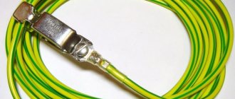
Copper wire
Practice shows that the most popular method by which pipelines are grounded is the use of copper wire. It is recommended to use wire with a diameter of 1...1.5 mm.
It is carried out both from the inside and from the outside, fastening it together at the joints using a wire jumper. The cold soldering method is used for connection. The outer wire installed at the end point needs to be carefully grounded.
Grounding the pipeline is the simplest, but at the same time mandatory, method of removing accumulated static charges of electricity. The main measure that prevents the occurrence of discharges accompanied by a spark is grounding with full shunting of taps and couplings.
The operation is performed using copper wire.
It is worth noting that the use of grounding technology in water pipes can significantly reduce the potential between the walls and the liquid itself, which is transmitted through it. However, no grounding system can completely eliminate the electrification of liquid substances.
TT system
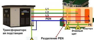
Schematic diagram of the TT system
In TT
The transformer substation has a direct connection of current-carrying parts to the ground. All open conductive parts of the building's electrical installation have a direct connection to the ground through a ground electrode, electrically independent from the neutral ground electrode of the transformer substation.
- Advantages: high resistance to N
on the way from the transformer substation to the consumer.
This destruction has no effect on PE
. - Disadvantages: requirements for more complex lightning protection (the possibility of a peak appearing between N
and
PE
), as well as the inability for a conventional circuit breaker to trace a phase short circuit to the device body (and further to
PE
). This is due to a fairly noticeable (30-40 Ohm) resistance of the local grounding.
Due to the above, the PUE recommends TT
only as an "additional" system (provided the supply line does not satisfy the
TN-CS
for re-earthing and mechanical protection
PEN
), and in outdoor installations where there is a risk of simultaneous contact with the installation and physical earth (or physically grounded metal elements).
However, due to the poor quality of most air lines in rural Russia, the TT
extremely popular there.
TT
requires the mandatory use of an RCD.
Typically, an introductory RCD is installed with a setting of 300-100 mA, which monitors short circuits between the phase and PE
, followed by personal RCDs for specific circuits at 30-10 mA to protect people from electric shock.
Lightning protection devices such as ABB OVR
, differ in design for
TN-C-
S and
TT
, the latter having a gas arrester between
N
and
PE
and varistors between
N
and the phases.
Isolated Neutral Systems
Artificial and natural grounding: advantages
An artificial circuit is specially made to implement grounding. The corresponding calculations are made, and it is determined what the optimal number of rods needs to be mounted to achieve the proper resistance. The work is labor-intensive and requires the purchase of certain materials to create the structure.
Examples of special grounding devices:
- iron beams, pipes, rods or angles installed in the ground;
- steel sheets of different shapes that are laid in the ground.
The advantage of electrical grounding using a natural grounding device is its low cost:
- minimal material costs;
- installation of a grounding loop does not require significant investment.
Advantages
Natural grounding agents are not made on purpose, but rather use what is at hand. In order to use metal structures as grounding conductors, they must fully comply with the requirements of the rules for electrical installations.
A natural grounding conductor can be combined with an artificial one. This scheme is used when large currents need to be diverted. The artificial ground electrode will direct the current to the natural one, through which it will go into the ground.
Natural contours are used quite often without artificial ones, on their own. Thanks to this approach, not only safe operation is ensured, but there is also a significant saving in materials spent on arranging the grounding loop.
Since the structure already exists, there is no need to install anything else, thanks to this you can significantly narrow the time frame allotted for installation and use a simple, inexpensive device.
The principle of connecting reinforced concrete structures
Connections between parts are made based on the formation of an electrical circuit between them (passes through metal). Embedded elements inside reinforced concrete structures are prepared in advance, through which the connection of technological or electrical equipment is realized for subsequent grounding.
The presence of bolts, rivets, welding or similar connections will allow the installation of a permanent electrical switching circuit. In the absence of such connections, there is an option to create similar connections using flexible jumpers. These elements are welded to parts of the structure. The standardization of the cross-section of jumpers is 100 sq. mm and above.
What are natural grounding agents made of?
Natural grounding conductors are used, most often, to ground an electrical installation, for example, metal parts (reinforcement) included in the construction of reinforced concrete elements, for example, the foundations of power line supports and substations, as well as the foundations of buildings. In addition, various types of metal underground communications, for example, pipelines, armor or cable sheaths, can be used as a natural grounding conductor. In some cases, it is permissible to use ground communications, for example, rail tracks, as a natural ground electrode.
Installation and connection of grounding conductors
Types of soil suitable for grounding construction:
- loam;
- clay;
- peat.
The various types of soils in which it is recommended to install ground electrodes are given. Types of soil not suitable for grounding construction:
- stone soil;
- rocky soil.
Listed are various types of soils in which it is not recommended to install grounding electrodes. Table 1. Indications of resistivity of various types of soil required when installing grounding.
Each type of soil has different properties under certain conditions. Grounding electrodes are often made of copper or ferrous metal coated with zinc.
Table 2. Recommended cross-sections of steel (uncoated) electrodes for grounding installation.
Table 3. Recommended cross-sections of copper electrodes for grounding installation.
Table 4. Recommended cross-sections of galvanized steel electrodes for grounding installation.
In the form of electrodes, the following can be used for grounding:
- steel corner with nominal dimensions 50 x 50 x 5, having a cross-section of 480 - 500 mm2;
- a strip of steel with nominal dimensions 40 x 4, having a cross-section of 160 - 200 mm2.
Images of several types of electrodes that are recommended for use with various types of grounding. Selected vertical grounding materials are not completely dug into the ground. There should be 20-25 cm of electrode above the surface. At the next stage, the electrodes are welded to steel corners installed around the perimeter in the form of a triangle.
Connection diagram for steel angles welded together around the perimeter in the form of a triangle.
Protective function of earthing
Protective grounding principle
The protective effect of grounding is based on two principles:
- Reducing the potential difference between a grounded conductive object and other naturally grounded conductive objects to a safe value.
- Discharge of leakage current when a grounded conductive object comes into contact with a phase wire. In a properly designed system, the appearance of leakage current leads to the immediate operation of protective devices (residual current devices - RCDs).
- In systems with a solidly grounded neutral - initiation of fuse operation when the phase potential hits a grounded surface.
Thus, grounding is most effective only in combination with the use of residual current devices. In this case, with most insulation failures, the potential on grounded objects will not exceed safe values. Moreover, the faulty section of the network will be disconnected within a very short time (tenths...hundredths of a second - the response time of the RCD).
service-gas.ru
There are two types of grounding: artificial and natural. The role of natural grounding is performed by parts of the metal structures of the object that are constantly located in the ground: foundation reinforcement, water supply, casing pipes, etc. Artificial grounding is a separate independent structure mounted in the ground. Almost every contractor is faced with the question when installing grounding, which grounding is better: artificial or natural?
To answer this question, let us turn to regulatory documents, namely paragraphs 1.7.54 and 1.7.109 of the “Rules for the Construction of Electrical Installations” (PUE). Here we see the answer: both natural and artificial grounding electrodes are suitable for grounding. Let's find out in what cases it is more correct to use one method or another? Let's look at each option in more detail.
Option 1. Natural grounding
If you decide to use a natural grounding system, then you need to know about many factors: the type of foundation of the object, its material, as well as the aggressiveness of the soil. Section PUE 1.7.109 outlines design options for the facility that can be used as a grounding conductor. The most common of these is the foundation. There are several types of foundations: strip, columnar, pile and slab. The choice of base depends on soil density, seismic activity, surface topography, groundwater level and soil freezing depth. The materials used are: reinforcement, concrete, brick, wood, rubble, asbestos-cement or metal pipes. Detailed information about the foundation can be found in the regulatory documentation (SNB 5.01.01-99 Foundations and foundations of buildings and structures). Thus, when deciding to use your foundation as a ground electrode, you need to make sure that it has electrically connected metal parts.
All elements of the natural grounding system must be combined into a common circuit and in contact with the ground to drain currents directly or through concrete. Also, the selected ground electrode must meet the requirements of the PUE regarding the cross-sectional area of the conductor (Table 1.7.4). During the operation of a natural ground electrode, destruction of its structure or disruption of the operation of devices associated with it must not be allowed.
Sewage and central heating pipes, as well as pipelines for flammable and explosive mixtures, are not allowed as a grounding conductor. Pipes easily corrode the metal, breaking the electrical contact. This type of grounding is certainly more economical: it does not require costs for materials, installation and dismantling of the grounding device, but during its long-term operation, repairing damaged areas will cost no less than installing a separate grounding.
Natural grounding
Option 2. Artificial ground electrode
It is a set of electrodes installed in the ground and connected to electrical equipment using a grounding conductor. Copper-plated steel, galvanized steel or ferrous metals are used as electrode materials:
- Copper-bonded steel has the highest electrical conductivity and adhesion to various materials. The bond between copper and steel is stronger than with zinc, which is why copper-plated rods are stronger than galvanized rods. Copper is less electrochemically active than zinc and steel, which increases service life up to 100 years.
- Galvanized steel is a corrosion-resistant material with low resistivity. Electrodes made of this metal are highly resistant to acidic environments with an average service life of 30 years.
- Ferrous metals have high mechanical strength, but quickly break down when used in an aggressive soil environment, forming rust and corrosion. And, as a result, we get a high current flow resistance, which poses a danger to human life.
The dimensions of the conductors must comply with the requirements of GOST R 50571.5.54-2013. Many options for installing a grounding device help to ensure the required contact area of the surface of the ground electrode with the ground, which in turn allows you to influence the value of the resistance to current spreading. The advantage of an artificial ground electrode is that it can be installed deep into the ground, where the resistivity is lower due to groundwater that flows down. This ensures the stability of the final resistance.
Artificial ground electrode
Let's summarize: you can choose any of the options described above as a grounding conductor, the main thing is to approach this issue responsibly. For the safety of your home and long service life, choose a grounding device with a corrosion-resistant coating manufactured in accordance with regulatory guidelines. Call or write to our Technical Center and we will select the necessary grounding kit for your facility.
www.zandz.ru
Grounding systems used in electrical engineering
Several grounding systems are used in electrical engineering - TN-C, TN-S, TN-CS, IT, TT. These designations are deciphered as follows:
۞ The first letter of the Latin alphabet determines how the power supply is grounded:
- T – the neutral conductor of the power source is connected to ground;
- I – any conductive parts are insulated from contact with ground.
۞ The second letter indicates the nature of grounding of exposed conductive parts of the electrical installation:
- T – exposed conductive parts are connected to the ground, regardless of the grounding of the power source;
- N - all exposed conductive elements are connected to the point at which the power source is grounded.
۞ the letters that are indicated in the designation after the letter N with a hyphen determine how the protective and working conductors are arranged:
- C – the functions of the protective and working conductors are performed by one common PEN;
- S – the functions of the protective PE and working N conductor are provided separately.
In the “Rules for Electrical Installations” these are the designations used.
TN-C system
The simplest and most “ancient” grounding scheme, in which the neutral and grounding conductors are combined. When a phase “breaks down” on conductive parts, the current goes into the ground, and the circuit breaker de-energizes the circuit.
However, this system has a significant drawback. Under heavy loads, the neutral wire may slowly “burn out”. In the event of a short circuit, which is formed when a phase “falls” onto the housing, the already damaged neutral can burn out so quickly that the machine does not have time to react - a shutdown current has not yet arisen in the circuit. As a result, the protective grounding will disappear along with the neutral, but the phase will remain on the housing, since the machine did not turn it off.
If a person touches conductive parts, his body forms a conductor between the phase and the ground. In this case, electric shock is inevitable.
TN-S system
This is a more modern system in which the neutral and ground conductors are separated throughout the circuit. This system is much more complex than TN-C, but it is also much safer. The third, grounded conductor in a single-phase network, or the fifth in a three-phase network, is connected to the ground loop at the transformer substation.
TN-CS system
The design of such electrical wiring involves combining a combined PEN wire and a separate grounding conductor. This happens, for example, if the wiring throughout the house is made with a separate grounding wire, which is connected to an independent grounding circuit, and the house is connected from the transformer substation using a combined PEN conductor.
This scheme turns out to be more economical compared to TN-S, since the longest section of the power line can be made without a separate grounding wire. However, this circuit is just as reliable as TN-S.
IT and TT systems
With the TT system, everything is very clear - the housing of the source (transformer substation) is grounded, and all electrical appliances in the house are separately grounded. This scheme is rare, but is found when installing electrical wiring in private homes.
The IT system is practically not found in everyday life. It is used in specific cases - for example, when supplying electricity to rooms with equipment sensitive to interference. The absence of grounding of the power source will minimize induced currents in the network. Safety is ensured by grounding each electrical appliance. This scheme is used in laboratories and hospitals.
Types of artificial grounding
The main regulatory document in Russia, which allows the use of different grounding systems, is PUE clause 1.7. It was developed taking into account the methods of constructing grounding systems, their classification and principles. The document was approved by a special protocol of the International Electrotechnical Commission.
The abbreviated names of existing systems are combinations of the first letters of French words.
- T – grounding.
- N – connection to neutral.
- I - isolation.
- C – connection of the working and protective neutral conductors into one wire.
- S – separate use of protective and working neutral conductors.
To understand the differences and implementation methods, you need to familiarize yourself with each variety in more detail.
TN grounding device
The most common type of grounding systems. Its essence is to connect the zeros to the ground along the entire length. This type has another alternative name - the supply of a solidly grounded neutral.
To implement the method, it is necessary to technologically drive a group of pins into the ground in a vertical position so that the depth is at least 2.5 meters. All pins must be connected to each other using a cable and strip into a single circuit of a residential building.
TN-C system
Quite an outdated system that is still used in older housing stock. The essence of the protection is that zero N also plays the role of a protective PE wire; two functions are combined in one conductor. The advantage of this method is its ease of implementation and low-cost production; it is intended for electrical appliances with a power of no more than 1000 V.
Today, this type is potentially dangerous because it does not have a single separate conductor. If during an emergency or emergency situation the neutral wire breaks, all the electrical potential is concentrated on the devices, and this already poses a danger to human health and life, and there is a possibility of a fire.
TN-S system
TN-S
A new grounding system is used in new buildings being designed. The essence of its implementation lies in the presence of a separate phase, neutral and protective conductor. PE and N conductors are separate components of the power supply system.
Of the accepted and approved methods of grounding the electrical network, the TN-S system is considered the safest and most reliable. One of the disadvantages is the high cost.
Grounding system TN-CS
TN-CS grounding system
This grounding system has absorbed the best qualities of its predecessors and partially eliminated their shortcomings. The method is relatively simple to implement; another advantage of the type is that it can be implemented during the reconstruction and modernization of outdated buildings. The point is to organize the TN-C system, here the neutral wire is divided into two conductors N and PE, then the TN-S method begins to be implemented.
However, the problem of the protective circuit of the TN-C system is still not resolved. If the bus breaks, all the electrical potential is concentrated on household appliances. This drawback can be overcome with the help of auxiliary structures, for example, a voltage relay, which is capable of automatically disconnecting devices from the network in an emergency.
Natural and artificial types of grounding
Natural grounding - structures in direct contact with the ground. The following are used as natural protection:
- Lead sheathed cables laid in trenches underground; rail tracks of non-electrified access roads, railways, etc.
- Reinforced concrete and metal structures of any building structures that are in direct contact with the ground.
- Underground water and sewer lines. Do not use metal pipes that carry explosive or flammable substances.
Artificial grounding As a rule, horizontal and vertical electrodes are used for artificial grounding. The role of vertical can be played by a twig or steel pipe, at least 3 meters long. The essence of the implementation is to immerse the upper ends into the ground and connect them with a strip of steel using a welding machine. This technology forms a grounding loop.
For safe use of electrical appliances, natural grounding conductors must be used. Their use allows you to save the family budget and time, since there is no need to construct artificial grounding conductors. If the natural type satisfies all the requirements of the PUE for resistance to spreading, the artificial one need not be built.
Comparison of artificial and natural contour
Pipelines located in the ground act as a natural grounding system. A natural circuit is two or more metal structures that are in contact with the soil for the safe use of household appliances. Natural grounding is also divided into the following types:
- Pipelines intended for various purposes located in the ground.
- Reinforcement of building structures, which is immersed in soil layers.
These types of protective contour must be associated with the object by at least two elements. As a rule, they are installed in different parts of the structure.
As a natural defense, it is prohibited to use:
- heating systems and sewer lines;
- pipes whose surface is coated with an anti-corrosion compound;
Artificial ground electrode - metal structures intended for transportation of flammable and toxic substances.
An artificial contour is a special structure made of metal. To work, they are immersed in layers of soil. The most common examples of artificial protective contours are:
- Metal sheets laid in the ground. They can have different shapes and sizes.
- Rods, angles, pipes and steel beams placed in the ground.
Deep ground electrode
The use of a deep grounding electrode can significantly reduce the area occupied by the grounding electrode on the surface, as well as increase its efficiency (reduce grounding resistance), since the electrode(s) of such a grounding electrode is located in soil layers with lower resistivity than in surface layers (due to higher humidity and soil density).
This method of constructing a ground electrode was not often used in the past due to the complexity of installation, which required the use of special construction equipment - a drilling rig.
Nowadays, with the widespread use of modular grounding, the installation of deep grounding electrodes has become simple and quick without the use of special equipment. Simplicity allows work to be done in basements.
Grounding device technologies
There are several ways to make a ground loop.
Most often, two of them are used:
- Modular-pin grounding.
- Traditional grounding.
Modular grounding design
For its construction, rods made of high-quality copper-coated metal are used. They are driven vertically into the ground to a depth of about 1 m, the diameter of the rods is 14 mm. 30 mm threads are cut along the edges of the rod and also coated with copper.
The metal parts of the structure are connected together with brass couplings. They are connected horizontally with steel strips with brass clamps or a set of copper wire is used for this. Also, a connection is made between the grounding loop and the distribution panel. To protect grounding elements from corrosion, the kit includes protective paste.
Traditional grounding
Such a system is made from ferrous metal: strips, pipes, corners. Three metal electrodes are driven in a triangle 3 m into the ground, with an interval of 5 m. Next, the electrodes are connected into a common circuit using a metal strip and electric welding.
Such grounding has several negative properties (for example, the complexity of creating a circuit and corrosion, which destroys the metal of the product), for this reason, in our time, they are trying to use a more advanced method of grounding instead.
Natural grounding elements
Most often, they are used for grounding electrical equipment. Metal elements of various reinforced concrete structures are used as natural grounding conductors, for example, the foundations of substations and power lines and the foundations of buildings.
Additionally, for natural grounding, parts of underground communications made of metal are connected, for example, cable armor and all kinds of pipelines are suitable, sometimes it is permissible to connect ground communications, for example, rail tracks are suitable for this purpose.
Section of grounding electrodes
To ensure reliable and long-term operation of grounding electrodes in terms of corrosion and mechanical resistance, minimum dimensions of grounding electrodes are adopted.
Copper
| Profile | Cross-sectional area, mm² | Diameter, mm | Thickness, mm |
| Rectangular | 50 | 2 | |
| Round wire (immersion depth < 0.5 m) | 25 | ||
| Cable | 25 | 1.8 for each wire | |
| Pipe | 20 | 2 |
Copper-plated steel (electrolytic deposition)
| Profile | Diameter, mm | Coating thickness, microns |
| Round rod | 14 | 100 |
"Black" steel (uncoated)
| Profile | Cross-sectional area, mm² | Diameter, mm | Thickness, mm |
| Rectangular | 150 | 5 | |
| Angular | 150 | 5 | |
| Round rod | 18 | ||
| Pipe | 32 | 3,5 |
Stainless steel
| Profile | Cross-sectional area, mm² | Diameter, mm | Thickness, mm |
| Rectangular | 90 | 3 | |
| Angular | 90 | 3 | |
| Round rod | 16 | ||
| Pipe | 25 | 2 |
Cink Steel
| Profile | Section area, mm² | Diameter, mm | Thickness, mm | Coating thickness, microns |
| Rectangular | 90 | 3 | 70 | |
| Angular | 90 | 3 | 70 | |
| Round rod | 16 | 70 | ||
| Pipe | 25 | 2 | 55 |
The need to electrically connect the grounding loop of lightning protection installed directly on the building with the grounding loop for electrical installations is prescribed in the current regulatory documents (PUE). We quote verbatim: “Grounding devices for protective grounding of electrical installations of buildings and structures and lightning protection of categories 2 and 3 of these buildings and structures, as a rule, should be common.” The 2nd and 3rd categories are the most common; the 1st category includes explosive objects for which increased lightning protection requirements are imposed. However, the presence of the phrase “as a rule” implies the possibility of exceptions.
Modern office and now residential buildings contain many life support engineering systems. It is difficult to imagine the absence of ventilation systems, fire extinguishing systems, video surveillance, access control, etc. Naturally, the designers of such systems have concerns that “delicate” electronics will fail as a result of lightning. At the same time, some doubts arise among practitioners about the feasibility of connecting the contours of two types of grounding and a desire arises “within the limits of the law” to design electrically unconnected groundings. Is this approach possible and will it actually improve the safety of electronic devices?
TN systems
Such designs are distinguished by the presence of a solidly grounded neutral and the connection to it of all network elements capable of conducting electricity.
The connection to the neutral is made using neutral conductors.
Electrical cabinets, panels and instrument housings are connected to the PEN conductor. This is done to create a short circuit when the wiring is pierced into the housing, as a result of which the circuit breakers de-energize the network going to the failed section of the network, thus preventing electric shock to people nearby.
System with zero and dissected working conductor
TN-S system
The TN-S system for safety is equipped with two, rather than one, neutral wire, one of them serves as a protective wire, and the second is used as a neutral conductor connected to a solidly grounded neutral. This design is the safest today, capable of effectively protecting against electrical shock.
The operating principle of this design is that only one phase is used to supply the operating voltage and zero.
The wiring is made with a wire of three cores, one of which serves as a zero and is connected to the input wire.
Functional grounding type TT
Functional grounding is used in conditions where it is simply impossible to organize a TN type grounding circuit. The essence of the implementation lies in two separated grounding devices. Most often used when laying overhead power lines. It is also used in emergency conditions of neutral conductors.
A special feature of protecting a person from electric shock is the mandatory installation and use of a residual current device with a differential current of no more than 30 mA.
Basic potential equalization system.
Construction of a basic potential equalization system - creation of an equipotential zone within an electrical installation in order to ensure the safety of personnel and the electrical installation itself when the lightning protection system is triggered, potential build-up and short circuits.
The main potential equalization system in electrical installations up to 1 kV must connect the following conductive parts:
1) neutral protective PE or PEN conductor of the supply line in the TN system;
2) grounding conductor connected to the grounding device of the electrical installation, in IT and TT systems;
3) grounding conductor connected to the re-grounding electrode at the entrance to the building;
4) metal pipes of communications entering the building...
6) metal parts of centralized ventilation and air conditioning systems….
7) grounding device of the lightning protection system of the 2nd and 3rd categories;
8) grounding conductor of functional (working) grounding, if there is one and there are no restrictions on connecting the working grounding network to the protective grounding device;
9) metal sheaths of telecommunication cables.
To connect to the main potential equalization system, all specified parts must be connected to the main ground bus using the potential equalization system conductors. (PUE clause 1.7.82)
An element of a structure, a utility system, an independent working grounding system (FE), etc., not connected to the GZH. – a gross violation of the integrity of the main potential equalization system. The appearance of a potential difference (the possibility of a spark) is a threat to the life of personnel and the safety of the facility.
Note: the spark gap shown in the figure is a specialized spark gap with low operating voltage for potential equalization systems. For example: “KFSU”, “EXFS..” series from DEHN.
The additional potential equalization system significantly improves the level of electrical safety in the room. Short conductors of protective grounding and potential equalization, connected to the bus, form an equipotential zone according to a principle similar to the main potential equalization system.
Third party conductive part - a conductive part that is not part of the electrical installation.
If we approach the definition formally, then both a metal door handle and hinges on a wooden door in a wooden house are third-party conductive parts.
Expert opinion
Viktor Pavlovich Strebizh, lighting and electrical expert
Any questions ask me, I will help!
9-1.6 with the main task of extremely limiting the potential difference that a person can fall under, simultaneously connected to both the ground and the body. If there is something you don’t understand, write to me!
Ground electrode, their varieties and functional features
- Natural grounding devices are best used in cases where they allow all the safety requirements placed on them to be met.
- It is recommended to use artificial grounding loops to reduce the magnitude of currents that will flow into the ground through natural grounding conductors.
- To a greater extent, you can get by using only natural grounding devices. This will primarily save the cost of purchasing additional materials, and will also significantly reduce labor and physical costs. In addition, the use of natural devices is much easier to use than artificial ones.
Grounding via reinforced concrete foundation
The choice of such a structure as a grounding device can only be carried out if the physical foundations of the foundation (hydrophilicity of concrete) correspond to the quantitative indicators of soil moisture.
It is permissible to implement such a technological grounding option only if the moisture content of the soil on which the object is located is above 3%. A lower indicator of this soil characteristic will affect the hydrophilicity of concrete: powerful electrical resistance will occur, and the reinforced concrete structure will lose the properties of the ground electrode.
It is more practical to use a natural grounding system using a reinforced concrete foundation under the following conditions:
- the presence of a non-aggressive environment (groundwater with minimal hardness);
- lack of waterproofing;
- the presence of additional foundation protection (bitumen coating).
Regulatory standardization of the use of this type of grounding conductor provides options when it is prohibited to use it in the grounding system of a facility.
Grounding resistance for various objects
In private homes where electrical networks with a voltage of 220-380 volts are used, the grounding resistance should not exceed 30 Ohms.
A maximum resistance not exceeding 10 ohms is allowed when connecting a gas pipeline and other dangerous equipment to the house. The same value is used when connecting lightning rods. For each type of equipment with increased danger, a local grounding device is installed.
All these average resistance indicators correspond to normal standard soils, the resistivity of which does not exceed 100 Ohm x m. With a higher resistivity of the soil, the resistance of the ground electrode increases proportionally.
Expert opinion
Viktor Pavlovich Strebizh, lighting and electrical expert
Any questions ask me, I will help!
In places accessible only to qualified personnel, for example, switchboard rooms of residential buildings, the main grounding bus should be installed openly. If there is something you don’t understand, write to me!
Grounding of electrical installations up to 1000V according to PUE 7
- The length of the conductors of the additional potential equalization system connecting the contacts of plug sockets, third-party conductive parts and electrical equipment housings should not exceed 2.5 m (?). Section 4 mm 2 Cu (PV-1, PV-3). See PUE 1.7.82 fig. 1.7.7.
- For the electrical installation of a building where non-flammable (VVG ng –FRLS...) cables are used, you should use cables of the PV-1, PV-3 grades (potential equalization conductors from the additional potential equalization system to the GZSh or panel grounding bus) with caution. This type of cable, when laid together with non-flammable cables, formally turns the entire system into a fire propagating system. In most cases, regulatory authorities take this calmly, but in some cases it is worth using non-flammable single-core cables of the same brand with appropriate markings.
- For buildings of preschool institutions, hospitals, special nursing homes, etc. The plastic boxes used must have a certificate of non-emission of toxic substances during combustion. The same applies to linoleum. Legrand, ABB... boxes supplied to Russia do not have such certificates. As an option - boxes from DKC, which use chalk as a bleaching agent and have all the necessary certificates.
Requirements for grounding electrical installations up to 1000 Volts
Equipment grounding is a set of technical measures that make it possible to obtain a reliable electrical connection between the protected enclosures of electrical installations and the ground. It is organized to protect operating personnel and people working on equipment from accidental electric shock.
In accordance with the requirements of GOST 12.1.030-81, protective grounding of the electrical installation should be performed:
- at a rated voltage of 380 V and above alternating current and 440 V and above direct current - in all cases;
- at a rated voltage from 42 V to 380 V AC and from 110 V to 440 V DC when working in conditions with increased danger and especially dangerous conditions according to GOST 12.1.013-78.
Important! With a properly equipped grounding system, a dangerous potential that gets onto the machine body, for example, will not cause any harm to the person who touches it.
This is explained by the fact that, when the insulation breaks down, the main part of the current charge flows along the grounding bus into the protective circuit, the resistance of which is an order of magnitude lower than the same indicator for the human body.
Natural grounding
According to the rules of the PUE, the housings of technological equipment and other devices must be connected to natural or artificial grounding conductors (IZU). When implementing the first of these methods, the following auxiliary elements are traditionally used:
- metal frames of structures laid in the ground that have direct contact with it;
- metal casings for cables laid directly in the ground;
- ordinary metal pipes (except for gas and oil pipelines);
- railroad tracks.
Please note: The use of ready-made structures greatly simplifies the solution to the grounding problem, simplifying the process.
In addition, their use in organizing effective grounding allows one to somewhat reduce the costs of its arrangement.
The importance of current flow resistance
The main requirement for groundings up to 1000 Volts is their ability to create a reliable chain for emergency current charges to flow into the ground. It is estimated by the amount of resistance that ground fault currents have to overcome.
According to regulatory documents (PUE, in particular), the grounding resistance (resistance to the spread of electric current) should be:
- in private homes with a supply voltage of 220 and 380 Volts, it should be no more than 30 Ohms.
- for industrial equipment (substation transformers, in particular, or generators and welding machines) should not exceed 4 ohms.
- in relation to the current source (generator or transformer) no more than 2, 4 and 8 Ohms, respectively, at phase-to-phase voltages of 660, 380 and 220 V three-phase power supply or 380, 220 and 127 V single-phase power supply.
Connecting elements in a structure
It doesn’t matter what the structural parts are made of, metal or reinforced concrete, the main thing is that they must be connected in such a way that an electrical circuit is formed in these parts, which will pass through the metal itself. If the structure is reinforced concrete, then the embedded parts in it should be additionally prepared. They must be present on each floor of the property.
Thanks to these embedded parts, the device can connect electrical or technological equipment that must be grounded. If there are connections in buildings in the form of bolts, rivets or welds, then they will be sufficient to install a permanent electrical circuit. If such connections are not available, then flexible jumpers can be used, which are welded to the structural elements. The cross-section of the jumpers should be from one hundred square millimeters.
What cannot be used from reinforced concrete structures as grounding conductors? If the prefabricated foundation is made of reinforced concrete, then it is better not to connect a natural ground electrode to it. If possible, it is better to first connect the reinforcement of nearby blocks to each other, and only then begin making natural grounding. If such a connection is not possible, then it is best to make an artificial ground loop.
Reinforced concrete structures are connected to each other as follows: if the building’s foundation is made of piles, then the reinforcement of the piles is connected to the foundation blocks or to the grillage reinforcement using electric arc welding. But such welding is not suitable for spatial columns and metal frames. In this case, spot welding is used.
samelectrik.ru
Artificial grounding: types, functions, requirements and installation
- The most dangerous option is when the metal body of the device is not grounded and the RCD is not installed at all. The contact of a phase with current-carrying parts does not manifest itself in any way, except for a noticeable shock upon accidental touch.
- In the absence of an RCD, the housing is connected to the established grounding circuit, and the leakage current along the drain circuit is very high. In this case, the device will work instantly and turn off the supply line or a separate circuit of it.
- In the presence of an RCD, the housing is not grounded, which is detected only when a leakage current flows, which will trigger the protection device. In a time of about 200-300 milliseconds, a person who touches the device will feel only a light electric shock.
- And finally, the safest option involves grounding the housing and simultaneously installing a separate RCD in this branch.