Operating principle of transformerless power supply
In transformer and pulse (which, in essence, are also transformer) power supplies, the supply level is reduced due to the transformation of the primary voltage into the secondary windings. You can approach it differently - suppress the excess voltage with a resistor (ballast resistance). Its resistance must be selected so that the load has the required level, and everything else falls on the ballast element. Such a transformerless power supply is essentially a voltage divider.
Operating principle of a transformerless power supply.
The ballast resistor is connected in series with the load, and the full load current flows through it. Excess voltage drops across the damping element. So, in order to get 12 volts at the consumer, you need to select the resistor value so that 220-12 = 208 volts drop across it. With a load current of 1 ampere, the resistance should be R=U/I =208/1=208 Ohm. From 10% of the series (E12) of ratings, you can choose a resistance of 200 Ohm or 220 Ohm. If you need to choose more precisely, you can choose from several elements the one whose actual resistance (taking into account 10% deviation) will be as close as possible to the calculated 208 Ohms.
Working diagrams
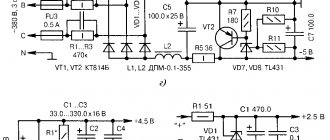
All described devices are made using common radioelements. Below are diagrams indicating all the parts.
In a power supply with transistor stabilizers, the KT940A can be replaced with a high-voltage one that can withstand more than 250 V, and the KT815G with another one with a minimum voltage of 80 V. With the specified details, the device can output up to 300 mA. To increase the current, transistors must be installed on radiators. If you install D814D instead of the KS512A zener diode, the output current of the device will decrease to 200 mA.
What are the pros and cons of such schemes?
This scheme contains two main advantages:
- absence of a bulky and difficult to manufacture winding element (transformer);
- reduced weight and dimensions.
The second advantage decreases sharply with increasing load current. So, for the example discussed above, for an output level of 12 V at a current of 1 A, 208 Watts will be dissipated by the resistor. An element for operation at such a current has dimensions comparable to the dimensions of a transformer and requires conditions for heat exchange with the environment.
200 Watt resistor.
This is where the pros end and the cons begin. One of the main ones is the high risk of electric shock . Despite the fact that only 12 volts drop across the load, each element of the circuit is at full line voltage of 220 volts relative to ground. Accidentally touching live elements at the same time as touching the ground can lead to dire consequences.
The second disadvantage of transformerless circuits is the pronounced dependence of the load voltage on the current consumed. So, for the considered circuit, with changing currents and a 208 Ohm resistor across the load, the voltage indicated in the table will drop.
| Load current, A | 0,25 | 0,5 | 0,75 | 0,95 | 1 | 1,05 |
| Ballast voltage, V | 52 | 104 | 156 | 198 | 208 | 218,4 |
| At load, V | 168 | 116 | 64 | 22 | 12 | 1,6 |
When the current changes by 5% in either direction, the voltage at the consumer changes significantly. This sharply reduces the scope of application of power supplies with ballast and does not allow, for example, the use of such a device as a laboratory power supply. This problem can be partially solved by using stabilizers at the output of the power supply (linear or pulsed), but the possibility of such a solution is also limited, especially for linear regulators. They are limited from above by the maximum power dissipation on the control element, and from below by the need for the minimum permissible voltage drop across it.
A switching stabilizer (not to be confused with a switching power supply!) does not dissipate (in theory) power on the key element, so theoretically there is no limit on excess voltage. It also does not need a voltage drop across the switch, so the range of supply voltages for it can be wider.
Another disadvantage of a transformerless power supply is low efficiency. Part of the power is uselessly dissipated on the ballast, and heat must be removed from the resistor. The problem of heat removal disappears if, instead of a resistor, a quenching capacitor is used , which has a reactance that depends on frequency (no heat is generated on it).
A capacitor can only be used as one of the divider arms in AC circuits.
To calculate ballast, you need to use the formula X=1/(2*π*f*C), where:
- X – capacitor reactance, Ohm;
- π – number “pi”, rounded equal to 3.14;
- f – frequency, for a household network is 50 Hz;
- C is the capacitance in farads.
Hence C=1/(2*π*f*X)=1/(314*X), to obtain the result in microfarads it is necessary to multiply by 1000000 (106), as a result the given formula will take the form C=3184/X. X is selected using the formula X=U/I. For the above example, X is still the same 208 Ohms, and the capacitance is 15.3 µF (the relationship here is the opposite - as the current increases, the capacitance must be increased, reducing the resistance). The problem is that it is difficult to select a capacitor with such accuracy. A number of available capacitances have a larger pitch, and a decrease in accuracy leads to the same effect as a change in current. Thus, using a 15 µF capacitor instead of 15.3 will lead to an increase in resistance to 212 Ohms and a change in the load voltage to 11.7 volts. In most cases, this is not critical, but the dependence of the power parameters on the characteristics of the capacitor is clearly visible. Selecting a container with a given accuracy is very problematic. It is also necessary to take into account that the capacitor must be designed with a reserve for the full amplitude voltage of the network, which is not 220, but 310 volts.
We recommend: Homemade power supply with voltage and current regulation
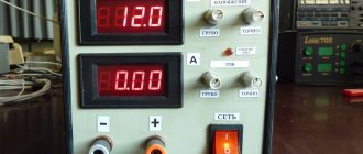
Experiment
In our experiment, we used resistors with a higher value than indicated in the calculations. A 300 ohm resistor (12V/300 ohms = 40mA) was used as a load resistor to test the load capacity of the power supply.
Output voltage = Vz - Vd = 12 - 0.7 = 11.3 V
Attention. Caution should be used when testing or using this circuit! Do not touch any points on the circuit, as some points on this circuit are live!
Source
Converter circuit for powering 90V thyratrons
To power the thyratrons with a voltage of approximately 90 V, a voltage converter circuit according to Fig. 4 with master oscillator 1 and element parameters: R1=R4=-1 kOhm, R2=R3=10 kOhm, C1=C2=0.01 μF.
Widely available low-power transistors can be used here. The multiplier has a multiplication factor of 12 and with the available supply voltage one would expect an output of approximately 200V, but in reality due to losses this voltage is only 90V, and its value quickly drops with increasing load current.
Rice. 4. Circuit of a voltage converter with a multistage multiplier.
Transformerless power supply: possible schematic solutions
Linear stabilizer chip
You can assemble a simple driver (stabilized current source) with your own hands using an inexpensive ($0.3) linear stabilizer chip LM317AMDT. The input of the DC-AC converter is supplied with a mains voltage of 220 V, 50 Hz.
A stabilized voltage of 12 V is obtained on the IC with a minimum set of elements in the harness (in the simplest version, only R1 and R2 are used). By selecting the value of the resistors, you can regulate the current in the load; with a total LED current of up to 0.3 A, the microcircuit works perfectly without a radiator. Below is a typical circuit diagram of a device based on the LM317 chip:
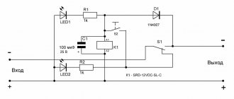
Charger
The most budget option, of course, is to use a charger from a cell phone. The charger board has very small dimensions and is suitable for powering a 12 V gadget with a power ≤ P rated. power supply. It is only necessary to replace the half-wave rectifier with a rectifier with double the voltage (add one diode and capacitor each). After modernization, we get the required 12 volts with a current of 0.5A and full isolation from the network.
As an alternative that does not require intervention in the design, a step-up DC-DC voltage converter (for example, 2-amp, 30mm x 17mm x 14mm, costing $1) with a USB connector can be connected to the output of the charger through an adapter. All you need to do is set the trimming resistor to the required voltage of 12 V and connect the converter to a gadget or stationary power receiving device.
Voltage converter (doubler)
The voltage converter (doubler) (Fig. 6) contains a master oscillator 1 (1 in Fig. 1.1), two amplifiers 2 (2 in Fig. 1.1) and a bridge rectifier (VD1 - VD4).
Rice. 6. High power voltage doubler circuit.
Block 1: R1 =R4=100 Ohm; R2=R3=10 kOhm; C1=C2=0.015 µF, transistors KT315.
Block 2: transistors GT402, GT404.
It is known that the power transmitted from the primary circuit to the secondary is proportional to the operating frequency of the conversion, therefore, simultaneously with its increase, the capacitance of the capacitors and, consequently, the dimensions and cost of the device decrease.
This converter provides an output voltage of 12V (idle). With a load resistance of 100 Ohms, the output voltage drops to 11 V; at 50 Ohm - up to 10 V; and at 10 Ohms - up to 7 V.
Scheme of the converter-inverter on the KR1006VI1 microcircuit
For voltage converter circuits built on the principle of pulse voltage multipliers, a wide variety of rectangular signal generators can be used.
Such generators are often built on the KR1006VI1 microcircuit (Fig. 14). The output current of this microcircuit is quite large (100 mA) and it is often possible to do without additional amplification stages.
The generator on the DA1 chip (KR1006VI1) produces rectangular pulses, the repetition rate of which is determined by the elements R1, R2, C2. These pulses from pin 3 of the microcircuit are fed to the voltage multiplier.
A resistive divider R3, R4 is connected to the output of the voltage multiplier, the voltage from which is supplied to the “reset” input (pin 4) of the DA1 microcircuit.
The parameters of this divider are selected in such a way that if the output voltage in absolute value exceeds the input voltage (supply voltage), generation stops. The exact value of the output voltage can be adjusted by selecting the resistances of resistors R3 and R4.
Rice. 14. Diagram of a voltage converter-inverter with a master oscillator on the KR1006VI1 microcircuit.
The characteristics of the converter - voltage inverter (Fig. 14) are given in table. 2.
Table 2. Characteristics of the voltage converter-inverter (Fig. 14).
| Upit, V | Iout, mA | Iconsumer, mA | Efficiency, % |
| 6 | 3,5 | 13 | 27 |
| 7 | 6 | 22 | 28 |
| 8 | 11 | 31 | 35 |
| 10 | 18 | 50 | 36 |
| 12 | 28 | 70 | 40 |
Voltage converter for controlling varicaps
A simple voltage converter circuit for controlling varicaps has been reproduced many times in various magazines. The converter produces 20 V when powered by 9 b, and such a circuit is shown in Fig. eleven.
A pulse generator close to rectangular is assembled on transistors VT1 and VT2. Diodes VD1 - VD4 and capacitors C2 - C5 form a voltage multiplier, and resistor R5 and zener diodes VD5, VD6 form a parametric voltage stabilizer.
Rice. 11. Diagram of a voltage converter for varicaps.
Voltage polarity inverter from (+) to (-)
To obtain an inverted output voltage, a converter based on a standard unit can also be used (Fig. 1). At the output of the device (Fig. 5), a voltage is generated that is opposite in sign to the supply voltage.
Rice. 5. Voltage inverter circuit.
In absolute value, this voltage is slightly lower than the supply voltage, which is due to the voltage drop (voltage loss) on the semiconductor elements. The lower the circuit supply voltage and the higher the load current, the greater this difference.
Voltage converter on a CMOS chip
Rice. 12. Circuit of a voltage converter on a CMOS chip.
A simple voltage converter using only a CMOS chip with a minimum number of external elements can be assembled according to the circuit in Fig. 12.
The main parameters of the converter at different supply voltages and load currents are given in Table 1.
Table 1. Parameters of the voltage converter (Fig. 12):
| Upit, V | Iout. mA | Uout, V |
| 10 | 5 | 17 |
| 10 | 10 | 16 |
| 10 | 15 | 14,5 |
| 15 | 5 | 27,5 |
| 15 | 10 | 26,5 |
| 15 | 15 | 25,5 |
What can 12 or 24 volt voltage be used for in everyday life?
In domestic environments, low voltage power supplies are often used. Portable/stationary electrical and electronic devices, as well as some lighting devices, are powered from 12 or 24V DC voltage:
- cordless electric drills, screwdrivers and electric saws;
- stationary pumps for watering gardens;
- audio-video equipment and radio-electronic equipment;
- video surveillance and alarm systems;
- battery-powered radios and players;
- laptops (netbooks) and tablets;
- halogen and LED lamps, LED strips;
- portable ultraviolet irradiators and portable medical equipment;
- soldering stations and electric soldering irons;
- chargers for mobile phones and power banks;
- low-current power supply networks in places with high humidity and landscape lighting systems;
- children's toys, Christmas tree garlands, aquarium pumps;
- various homemade radio-electronic devices, including those based on the popular Arduino platform.
Most devices run on batteries and Li-ion batteries, but the use of commodity items is not always justified in terms of operating costs. Batteries can be charged 300–1500 times, but galvanic cells with high energy capacity and low self-discharge current are expensive. It will be noticeably cheaper to purchase batteries, especially salt and alkaline ones, but such elements will have to be changed frequently. Moreover, to provide a supply voltage of 12 V, you will need 8 series-connected AA or AAA batteries or 1.5-volt “tablets” in a 27A housing.
Therefore, in places with access to a 220 V 50 Hz household network, it is more rational to use a power supply to power electrical receivers with an amperage of more than 0.1 A.
Source
Making a 12V power supply with your own hands
You can make a transformerless unit yourself. First you need to select one of the given schemes.
You will need the following tools and materials:
- soldering iron, flux, solder;
- radio components shown in the figure;
- insulated wires for forming leads;
- foil material (textolite, getinaks) for the manufacture of printed circuit boards;
- drill with a thin (0.5-1 mm) drill;
- wire cutters or scissors for cutting leads;
- pliers or tweezers.
To create a board you will need an etching composition, for example:
- ferric chloride solution;
- a mixture of table salt (2 tbsp.), copper sulfate (4 tbsp.) and 0.5 l of water.
The boards are etched for 2-6 hours. To reduce this period, it is recommended to heat the solution to +50...+60 °C.
Next, perform the following steps:
- They draw tracks on the board and etch them.
- Drill holes in the right places.
- The legs of the parts are cut and molded.
- Insert them into the holes and solder them.
- Install radiators (if necessary).
After assembling the board, wires with the necessary connectors are connected to it. To switch on 220 V, a power plug is used, and some kind of connector or special plug is placed at the output.
Source
Master oscillator
The transformerless master oscillator can be made according to a standard circuit, the basic element 1 of which (Fig. 1) is made on the basis of a symmetrical multivibrator.
As an example, the block elements may have the following parameters: R1=R4=1 kOhm; R2=R3=10 kOhm C1=C2=0.01 µF. Transistors are low-power, for example, KT315. To increase the power of the output signal, a standard amplifier block 2 was used.
Rice. 1. Schemes of basic elements of transformerless converters: 1 - master oscillator; 2 - typical amplifier block.
Basic ways to downgrade
For example, a “running” transformer with a frequency of 50 Hz with a relatively low power of 200 W, made on transformer hardware, weighs more than 1 kilogram and costs from $9–18. This not only makes the power supply bulky, but also significantly increases the cost of the device.
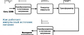
The transformers implement a classic scheme for reducing and then converting alternating voltage (AC) to direct voltage (DC) along the “transformer → rectifier → stabilizer” circuit.
There is a more complex scheme for constructing a “rectifier → pulse generator → transformer → rectifier → stabilizer” switching power supply, which has smaller dimensions.