Connecting consumers to domestic or industrial electrical networks using a cable of less power than necessary can cause serious negative consequences. This will primarily cause circuit breakers to continually trip or fuses to blow. If unprotected, the power wire or cable may burn out. As a result of overheating, the insulation melts and a short circuit occurs between the wires. To avoid such situations, it is necessary to calculate the current by power and voltage in advance, depending on the existing single-phase or three-phase electrical network.
Total power and its components
Electrical power (P) in physics is a measure that shows how quickly the transformation or transfer of electricity occurs. The unit of measurement is watt (W, W). The value of P depends on the voltage (U) and current (I) in the closed circuit.
For direct current, the load consumed by P is the result of the product of current and voltage:
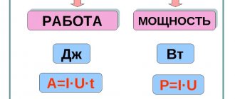
P = I*U (A*B = W).
P in a constant current circuit
Attention! In this case, the values of both electrical characteristics are constant, which means that at every second of time their values are instantaneous.
The formula changes form if there is a source of electromotive force E (EMF) in the circuit:
P = I*E.
For circuits where the current changes its values periodically along a sinusoid, this formula is not suitable. It is necessary to calculate P based on its instantaneous values in the time interval.
The total power S in its value corresponds to the expression:
S = U*I,
Where:
- U – potential difference at the terminals, (V);
- I – current, (A).
To designate S, use the non-systemic unit B*A (V*A).
Loads included in variable current circuits can be:
- active;
- reactive: capacitive or inductive.
Active load (AH)
A similar load is the elements of devices that have active resistance. The working part of such devices heats up when electricity passes through them.
The current passing through the load does work, which is spent on heating and releasing thermal energy. How is this load measured? It is measured in ohms (ohms).
Examples of AN include: iron, electric stove, hair dryer coils, lamp filament, resistive resistance.
For your information. AN behaves the same way both with constant and with time-varying current.
Example AN
Capacitive load
Devices that can store energy in an electric field and create recirculation (full or partial return) of power are called capacitive loads. A capacitive load (EC) at an alternating voltage, passing current, shifts its phase forward by 900.
The main elements related to EN are:
- capacitors;
- cable lines (capacitance between cores);
- Power lines (power lines) of ultra-high voltage;
- generators operating in overexcitation mode.
EH delivers reactive power (Q).
Circuit with capacitor
Inductive load (IN)
A load in which the current is phase-shifted back from the voltage by 900 is called inductive. She also consumes Q.
Chain with coil
When an inductor (choke), which has a low active resistance, is connected to an alternating voltage network, an emf is formed in it. Electromotive force opposes applied voltage.
Important! In the case of pure inductance L, the resistance to sinusoidal current increases with increasing frequency. The average power P released by such a load is zero.
Examples of ID are:
- asynchronous motors;
- electromagnets;
- chokes;
- reactors;
- transformers;
- rectifiers
This also includes thyristor converters.
How to determine the maximum current load
The useful power shows the maximum value in a situation where the load resistance R is compared with the same parameter inside the source - r.
R = r.
P max = E2 / 4r, where E is the driving force of the current source.
To calculate the maximum current load for an electrical device, you need to know the rated load parameter and the AC input voltage. The technical data sheet of the device, manual or emblem contains the first indicator.
For example, when the appliance rating (P) is 12 W, the maximum current consumption at AC voltage will be for:
- 120 V – I = 12/120 = 0.100 A or 100 mA.
- 220 V – I = 12 / 220 = 0.055A or 55 mA.
If necessary, the amount of electricity consumed is expressed through a complex value. For this purpose, basic relationships are used, impedance is used instead of resistance.
Negative influence of reactive load
Three-phase network power calculation
If we represent the powers in the form of vectors, then the vectors P and Q in sum will give the total power. It is equal to:
S = √ (P2 + Q2).
Total S graph
The formulas for P and Q are:
- P = U*I*sinφ (for a single-phase network) and P = √3* U*I*sinφ (for a three-phase network);
- Q = U*I* cosφ (for a 220 V network) and Q = √3*U*I* cosφ (for a 380 V line).
For your information. Calculations for a three-phase network are correct for symmetrically loaded phases. Otherwise, the powers of all phases are summed up.
The smaller the angle φ between vectors S and P, the higher the power factor cosφ. Complete coincidence of vectors is prevented by Q. The load on power lines and power supply system equipment increases with a large angle value. Overheating of wires and wear of power system equipment occurs.
In practice, the main consumers of manufacturing enterprises are transformers, electric motors and long-distance cables. Therefore, IN is in the lead there, consuming Q. There is an overconsumption of consumed energy, for which enterprises are punished with fines.
Reactive power (RP) carries with it the following disadvantages:
- does not perform useful work;
- causes unnecessary energy consumption and unexpected overload of electrical equipment;
- may cause an emergency.
To compensate for PM, it is necessary to include capacitive elements in parallel with such consumers. For this purpose, Q compensation devices are built. They can be capacitor or inductive, depending on what type of reactive load predominates. Capacitor units, including capacitor batteries, are placed both at power substations and in separate blocks. Such compensation replenishes the reactive component of the energy consumed from the supplier.
Complete condenser unit KKU
Instantaneous electrical power: calculating the value
This indicator establishes the instantaneous values of the measured data. The key definition is considered taking into account the fact that a single simple charge (q) moves in a certain time Δt. To perform a specific action, the energy of electric current PF1-F2 = U/ Δt or (U/ Δt) x q = U x (q/ Δt) is expended. The formula takes into account the movement of q over the period Δt. Since the current, according to the classical definition, is equal to the charge moving from F1 to F2 (I = q/ Δt), the final expression is derived: PF1-F2 = U x I.
Conditionally assuming that the time period is very short, we obtain the instantaneous power for part of the electrical circuit P(t) = U(t) x I(t). The same conclusions can be drawn taking into account the corresponding resistance parameter: P (t) = (I (t))2 x R = (U(t))2/ R.
Calculation of power by current and voltage
Electric current power formula
You can calculate consumption P by knowing these two parameters I and U of the network. Before choosing cables or wires for wiring in an apartment, you need to decide on the P consumers that can be connected to them. The calculation is made after the measuring instruments record the current readings of the current strength I (A), as well as the voltage U (V).
Single-phase 220 volt network
When connecting an active load to the circuit, use the formula: P = U*I. If there is a phase shift between U and I, use the formula: P = U*I* cosφ.
Three-phase network voltage 380 V
In a three-phase AC network with a phase shift, the result of the last formula is multiplied by √3. The value of the angle cosφ can be clarified in the reference book.
Cosφ table for household devices
When choosing a wire cross-section, the total power of future consumers and the network voltage are usually known.
All you need is the current strength, the formula through power and voltage is:
I = P / (U *cosφ).
The formula for calculating current using power and voltage has the following components:
- P – known power of the device, (W);
- U – supply voltage, (220/380 V);
- cosφ – phase shift angle.
Current calculation can be done using an online calculator.
Online calculator – general view of the interface
Selecting the rating of the circuit breaker
Applying the formula I = P/209, we find that with a load with a power of 1 kW, the current in a single-phase network will be 4.78 A. The voltage in our networks is not always exactly 220 V, so it would not be a big mistake to calculate the current strength with a small margin like 5 A for every kilowatt of load. It is immediately clear that it is not recommended to connect an iron with a power of 1.5 kW to an extension cord marked “5 A”, since the current will be one and a half times higher than the rated value. You can also immediately “graduate” the standard ratings of the machines and determine what load they are designed for:
- 6 A – 1.2 kW;
- 8 A – 1.6 kW;
- 10 A – 2 kW;
- 16 A – 3.2 kW;
- 20 A – 4 kW;
- 25 A – 5 kW;
- 32 A – 6.4 kW;
- 40 A – 8 kW;
- 50 A – 10 kW;
- 63 A – 12.6 kW;
- 80 A – 16 kW;
- 100 A – 20 kW.
Using the “5 amperes per kilowatt” technique, you can estimate the current strength that appears in the network when connecting household devices. You are interested in peak loads on the network, so for the calculation you should use the maximum power consumption, not the average. This information is contained in the product documentation. It is hardly worth calculating this indicator yourself by summing up the rated powers of the compressors, electric motors and heating elements included in the device, since there is also such an indicator as the efficiency factor, which will have to be assessed speculatively with the risk of making a big mistake.
When designing electrical wiring in an apartment or country house, the composition and passport data of the electrical equipment that will be connected are not always known for certain, but you can use the approximate data of electrical appliances common in our everyday life:
- electric sauna (12 kW) - 60 A;
- electric stove (10 kW) - 50 A;
- hob (8 kW) - 40 A;
- instantaneous electric water heater (6 kW) - 30 A;
- dishwasher (2.5 kW) - 12.5 A;
- washing machine (2.5 kW) - 12.5 A;
- Jacuzzi (2.5 kW) - 12.5 A;
- air conditioner (2.4 kW) - 12 A;
- Microwave oven (2.2 kW) - 11 A;
- storage electric water heater (2 kW) - 10 A;
- electric kettle (1.8 kW) - 9 A;
- iron (1.6 kW) - 8 A;
- solarium (1.5 kW) - 7.5 A;
- vacuum cleaner (1.4 kW) - 7 A;
- meat grinder (1.1 kW) - 5.5 A;
- toaster (1 kW) - 5 A;
- coffee maker (1 kW) - 5 A;
- hair dryer (1 kW) - 5 A;
- desktop computer (0.5 kW) - 2.5 A;
- refrigerator (0.4 kW) - 2 A.
How to connect a pass-through switch: connection diagrams
Calculation of cable cross-section by power: practical advice from professionals
The power consumption of lighting devices and consumer electronics is small; in general, the total power of lighting devices can be estimated at 1.5 kW and a 10 A circuit breaker is sufficient for a lighting group. Consumer electronics are connected to the same outlets as irons; it is not practical to reserve additional power for them.
If you sum up all these currents, the figure turns out to be impressive. In practice, the possibility of connecting the load is limited by the amount of allocated electrical power; for apartments with an electric stove in modern houses it is 10 -12 kW and at the apartment input there is a machine with a nominal value of 50 A. And these 12 kW must be distributed, taking into account the fact that the most powerful consumers concentrated in the kitchen and bathroom. Wiring will cause less cause for concern if it is divided into a sufficient number of groups, each with its own machine. For the electric stove (hob), a separate input with a 40 A automatic circuit breaker is made and a power outlet with a rated current of 40 A is installed; nothing else needs to be connected there. A separate group is made for the washing machine and other bathroom equipment, with a machine of the appropriate rating. This group is usually protected by an RCD with a rated current 15% greater than the rating of the circuit breaker. Separate groups are allocated for lighting and for wall sockets in each room.
You will have to spend some time calculating powers and currents, but you can be sure that the work will not be in vain. Well-designed and high-quality electrical wiring is the key to the comfort and safety of your home.
Power at currents: direct and alternating
Calculation of voltage drop in a cable
When it becomes necessary to calculate how much installed equipment will consume, you need to remember that there is a difference between the P value when applying DC and AC voltage.
The formula P for constant current shows P as the product of the instantaneous values of I and U. In this case, the moment in time can be absolutely any.
The expression P under conditions of sinusoidal electron motion takes into account the angle by which the phases of the current and voltage are shifted. The cosine of this angle is multiplied by the product of current and voltage over a period of time T. This is the period of time during which the current changes its value from positive to negative:
T = 1/f, where f is the frequency of 50 Hz.
What is it measured in?
The unit of measurement of electrical power is W for Russia. By international standards - W. This is the energy provided per unit of time. One W is equal to a joule per second (J/s). Moreover, a joule is a unit of electrical power, a second is a unit of time.
For small values, multiple prefixes are used: “milli-”, “micro-”, for large values - “mega-”. For example: 5,800 W = 5.8 kilowatts = 5.8 kW.
When you multiply 1 Kilowatt by 1 hour, you get a Kilowatt-hour (kW x h). This is a unit of measurement of the amount of electricity provided to subscribers. It is used by energy enterprises that own the appropriate equipment (generators and transformer substations). They generate and convert the produced electricity, which is then distributed to consumers.
In the same way, the energy capacity of batteries is measured in units of ampere hours (Ah). Portable types of energy storage batteries are measured in milliampere hours (mAh).
The energy in batteries is measured in milliamp hours (mAh). Source listtopa.ru
For the unit of measurement Watt, according to international standards, the letter designation W is allocated after James Watt. He was the first to use the term “horsepower,” which today is an obsolete unit of the W parameter.
Energy conversion indicators:
- horsepower (HP) - 746 W;
- kilo Watts (kW) – 1×1000 W;
- megawatts (MW) −1×1000000 W;
- gigawatt (GW) – 1×1000000000 W.
Today, "horsepower" is used to indicate the second measure of engine power in vehicles.
Features of calculations in alternating electricity circuits
To perform calculations of P, the load consumed in circuits of varying electricity, it is necessary to clearly separate the switching circuits. They can be single-phase or three-phase.
In single-phase circuits, P is found by multiplying the current value by the voltage value (220 V). In this case, the presence of a phase shift between them is taken into account.
In three-phase networks with a voltage of 380 V, two cases are considered:
- symmetrical load per phase;
- asymmetric phase load.
In the first case, P is found using the formula:
P = √3*U*I* cosφ.
In the second case, it is necessary to calculate P for each phase (A, B, C). P value is the result of the summation:
P total = PfA + PfB + PfS.
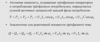
Attention! When it is necessary to find the total power of a three-phase circuit, the values of reactive Q are found using the same principle.
It is also possible to calculate the current by power, knowing what voltage: phase (220 V) or linear (380 V), by expressing it from the general formula P.
What determines the load of electric current?
Existing electrical wiring lines experience resistance during the movement of electrons, which characterizes voltage loss. Circuits where an alternating current source is present have one feature - the key role here is played by a sinusoidal oscillation of electrical indicators.
Sinusoidal oscillation of electrical indicators. Source urpsvet.ru
The following information will allow you to select the best calculation method based on actual network conditions.
Calculation of power consumption
The need arises in calculating electrical power when it is necessary to determine how much energy a particular consumer consumes. Or to calculate the load that the room wiring wires must withstand. To select the diameter of the conductor that will be used for wiring, you need to calculate the total power consumption Ppotr of all household appliances simultaneously plugged into the outlet.
Pin = Pnom*T,
Where:
- Pnom – rated power of the device, (W);
- T – operating time of the device, (h).
If an incandescent lamp with Pnom = 60 W operates for four hours during the day, then Pin = Pnom * T = 100*4 = 400 W.
Table for determining Pnom of some household appliances
Electrical Appliances Parameters
Every modern apartment must be equipped with electrical appliances. To connect them to the network, it is necessary to draw up a schematic diagram where the loads connected to individual lines will be distributed in coordination with each other. It is necessary to build in a circuit breaker based on the PUE to prevent emergency situations.
First, the electrical wiring parameters are clarified. Then they are checked according to the group diagram for connecting to the network of household electrical appliances.
Standard characteristics of electrical power consumption (W):
- desktop computer – 170-1,250;
- LCD TV – 120 – 265;
- laptop – 40-280;
- air conditioning – 1,200 – 2,500;
- iron – 450-1850.
To protect the network, you need an automatic machine; we choose it taking into account all the significant factors.
Automatic switch for protecting the electrical network Source vmasshtabe.ru
It is important to pay attention to loads that have increased reactive energy parameters.
Calculation of electrical circuits
All formulas used to calculate electrical circuits follow from one another.
Electrical characteristics relationships
So, for example, using the formula for calculating power, you can calculate the current strength if P and U are known.
To find out how much current an iron (1100 W) connected to a 220 V network will consume, you need to express the current strength from the power formula:
I = P/U = 1100/220 = 5 A.
Knowing the calculated resistance of the electric stove spiral, you can find P of the device. Power through resistance is determined by the formula:
P = U2/R.
There are several methods that allow you to solve the problems of calculating various parameters of a given circuit.
Methods for calculating electrical circuits
Calculating power for various types of current circuits helps to correctly assess the condition of power lines. Household and industrial devices selected in accordance with the specified parameters Pnom and S will work reliably and withstand maximum loads for years.
Examples of problems
For example, let's consider calculations on sections of an electrical circuit with serial and parallel connections of elements. The first option provides for a situation where all parts are connected one after another from one pole of the power source to the other.
Rice. 3. Sequential calculation circuit
As you can see in the figure, as a source we use a battery with a nominal voltage of 9 V and three resistors of 10, 20 and 30 Ohms, respectively. Since the rated current is not known to us, we will make the calculation using voltage and resistance:
P = U2/R = 81 / (10+20+30) = 1.35 W
For a parallel connection diagram, let's take as an example a section of a circuit with two resistors and one current source:
Rice. 4. Parallel connection diagram
As you can see, for the convenience of calculations, we need to bring the resistors connected in parallel to an equivalent circuit, which will result in:
Rtot = (R1*R2) / (R1+R2) = (10*15) / (10+15) = 6 Ohm
Then we can find out the required load rating through the value of current and resistance:
P = I2*R = 25*6 = 150 W
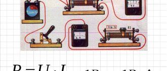
Current measuring instruments
Electrical measuring instruments are a special type of devices that are used to measure many electrical quantities. These include:
- AC ammeter;
- AC voltmeter;
- Ohmmeter;
- Multimeter;
- Frequency meter;
- Electric meters.
Ammeter
To determine the current strength in an electrical circuit, you need to use an ammeter. This device is connected to the circuit in series and, due to its negligible internal resistance, does not affect its state. The ammeter scale is graduated in amperes.
In a classic device, a measured current passes through an electromagnetic coil, which creates a magnetic field that causes the magnetic needle to deflect. The deflection angle is directly proportional to the measured current.
Classic ammeter
An electrodynamic ammeter has a more complex operating principle. It contains two coils: one is movable, the other stands still. They can be connected to each other in series or in parallel. When current passes through the coils, their magnetic fields begin to interact, which as a result causes the moving coil with an arrow attached to it to deviate by a certain angle proportional to the magnitude of the current being measured.
Voltmeter
A voltmeter is used to determine the voltage (potential difference) across a section of the circuit. The device must be connected parallel to the circuit and have high internal resistance. Then only hundredths of the current will enter the device.
School voltmeter
The principle of operation is that inside the voltmeter there is a coil and a series-connected resistor with a resistance of at least 1 kOhm, on which the volt scale is calibrated. The most interesting thing is that the resistor actually registers the current strength. However, the divisions are selected in such a way that the readings correspond to the voltage value.
Ohmmeter
This device is used to determine electrically active resistance. The principle of operation is to change the measured resistance into a voltage directly dependent on it thanks to an operational amplifier. The desired object must be connected to a feedback circuit or to an amplifier.
If the ohmmeter is electronic, then it will work on the principle of measuring the current flowing through the required resistance at a constant potential difference. All elements are connected in series. In this case, the current strength will have the following dependence:
I = U/(r0 + rx),
where U is the emf of the source, r0 is the resistance of the ammeter, rx is the desired resistance. According to this dependence, resistance is determined.
Electronic ohmmeter
Multimeter
The devices given as an example are used today only in schools for physics lessons. Multimeters were invented for professional tasks. The most common device includes simultaneously the functions of an ammeter, voltmeter and ohmmeter. The device can be either easily portable or huge stationary with a large number of possibilities. The name “multimeter” was first applied specifically to a digital meter. Analog devices are more often called “avometer”, “tester” or simply “Tseshka”.
Universal multimeter
The work of current is a complex but very important topic in electrodynamics. Without knowing it, you will not be able to solve even the simplest problems. Even electricians use job finding formulas to make the necessary calculations.
Energy can be of two types: reactive and active.
Active is the true electrical power that produces real work in the load, W shows this parameter. It converts energy into mechanical, thermal and other forms.
If you turn on a powerful unit or capacitor, the voltage inside the network drops. Such loads create an oscillating circuit that receives energy from the power source. In this situation, only P act components perform useful functions. The active indicator is calculated in the following way:
- U x I – direct current (alternating current with a resistive load);
- U x I x cos fi – for a single-phase 220 V line;
- U x √3 x cos fi = U x 1.7321 x cos fi – 3-phase network, U x √3 x 380V.
There are other types of energy, but more on that later.
Active and passive energy Source ppt-online.org
Reactive power
This indicator shows the loads that are created in devices due to fluctuations in the energy of the electromagnetic field.
Reactive power, regardless of the absence of useful work, must be taken into account to correctly evaluate key network data. Cables and wires, when current passes through them in any direction, heat up. This happens quite cyclically. Energy effects at high intensity:
- damage cable cores and protective insulation;
- contribute to the occurrence of a short circuit;
- destroy the windings of transformers and drives.
Reactive power is expressed as VA (volt-amperes) and is calculated by multiplying the voltage by the current and the shear angle:
P r = U x I x sin fi.
When connecting a load with capacitive parameters, the value becomes negative, when inductive it becomes positive. Since the characteristics of the magnetic field change, the unit of measurement for reactive power is VA.
If the parameters of total electrical power are shown as vectors, a triangle appears. The length of its sides will be equal to the amount of electricity consumed by a particular component. The angle between the apparent power (Pap) and the active power (ϕ) is used for calculations. The total value is determined by the expression: P total = √((P act)2 + (P react)2).
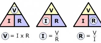
Ohm's Law Formula
In 1827 Georg Simon Ohm
discovered the law of electric current. The Law and the unit of measurement of resistance were named after him. The meaning of the law is as follows.
The thicker the pipe and the greater the water pressure in the water supply (as the diameter of the pipe increases, the resistance to water decreases) - the more water will flow. If we imagine that water is electrons (electric current), then the thicker the wire and the higher the voltage (as the cross-section of the wire increases, the current resistance decreases) - the greater the current will flow through the circuit section.
The current flowing through an electrical circuit is directly proportional to the applied voltage and inversely proportional to the value of the circuit resistance.
where
I
is the current strength, measured in amperes and denoted by the letter
A
;
U
– voltage, measured in volts and denoted by the letter
B
;
R
– resistance, measured in ohms and denoted
Om
.
If the supply voltage U
and the resistance of the electrical appliance
R
, then using the above formula, using an online calculator, it is easy to determine the strength of the current flowing through the
circuit I.
| Online calculator for determining current strength | |
| Voltage, V: | |
| Resistance, Ohm: | |
Using Ohm's law, the electrical parameters of electrical wiring, heating elements, and all radio elements of modern electronic equipment, be it a computer, TV or cell phone, are calculated.