What it is
Current resonance is a type of state of an electrical circuit when the general appearance of current indicators coincides in phase with the voltage level, and the reactive power is zero or it is presented in active form.
. Current resonance
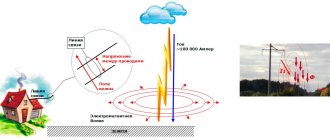
This scenario is typical for alternating current and has not only positive properties, but also some undesirable consequences. Thus, thanks to resonance, radio technology, automation and wire telephony work, but at the same time, overvoltages and malfunctions in the electrical system occur.
Definition from the textbook
Under what conditions does it occur?
The condition for this phenomenon to occur is equal conductor frequencies, where BL=BC. That is, capacitive and inductive conductivity must be equal. Only then is a similar phenomenon of current resonance observed in an electrical circuit. It can be either positive or negative. Any radio receiver has an oscillating circuit, which, due to inductive or capacitive changes, is tuned to the desired radio wave signal. In another case, this leads to voltage surges or current in the circuit and an emergency situation occurs.
In laboratory conditions, it occurs at a time when the capacitance changes and the inductance of the coil L does not change. In this case, the formula looks like Bc=C
Under what conditions does it occur?
What is resonance?
Definition of the phenomenon by TOE: electrical resonance occurs in an electrical circuit at a certain resonant frequency, when some parts of the resistance or conductivity of the circuit elements cancel each other. In some circuits, this occurs when the impedance between the input and output of the circuit is almost zero and the signal transfer function is close to unity. In this case, the quality factor of this circuit is very important.
Connection of two branches at resonance
Signs of resonance:
- The components of the reactive branches of the current are equal to each other IPC = IPL, antiphase is formed only when the net active energy at the input is equal;
- The current in individual branches exceeds the entire current of a particular circuit, while the branches are in phase.
In other words, resonance in an AC circuit implies a special frequency, and is determined by the values of resistance, capacitance and inductance. There are two types of current resonance:
- Consistent;
- Parallel.
For series resonance, the condition is simple and is characterized by minimal resistance and zero phase, it is used in reactive circuits, and it is also used in branched circuits. Parallel resonance or the concept of an RLC circuit occurs when the inductive and capacitive inputs are equal in magnitude but cancel each other out since they are at an angle of 180 degrees from each other. This connection must be constantly equal to the specified value. It has received wider practical application. The sharp minimum impedance that it exhibits is beneficial for many electrical household appliances. The sharpness of the minimum depends on the resistance value.
An RLC circuit (or circuit) is an electrical circuit that consists of a resistor, inductor, and capacitor connected in series or parallel. The RLC parallel oscillating circuit gets its name from the abbreviation of the physical quantities representing resistance, inductance and capacitance, respectively. The circuit forms a harmonic oscillator for the current. Any oscillation of the current induced in the circuit fades over time if the movement of the directed particles is stopped by the source. This resistor effect is called attenuation. The presence of resistance also reduces the peak resonant frequency. Some resistance is unavoidable in real circuits, even if a resistor is not included in the circuit.
Resonance is a mode of operation of a circuit that includes inductive and capacitive elements in which its input resistance (input conductance) is real. The consequence of this is that the current at the input of the circuit is in phase with the input voltage.
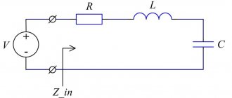
Resonance in a circuit with elements connected in series (voltage resonance)
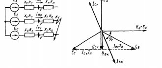
For the circuit in Fig. 1, we have
Where
| ; | (1) |
| . | (2) |
Depending on the ratio of the quantities and, three different cases are possible.
1. Inductance predominates in the circuit, i.e. , and consequently,
. This mode corresponds to the vector diagram in Fig. 2, a.
2. Capacitance predominates in the circuit, i.e. , which means . This case is reflected in the vector diagram in Fig. 2, b.
3. - case of voltage resonance (Fig. 2,c).
Voltage resonance condition
| . | (3) |
Moreover, as follows from (1) and (2), .
At voltage resonance or modes close to it, the current in the circuit increases sharply. In the theoretical case, at R=0 its value tends to infinity. According to the increase in current, the voltages on the inductive and capacitive elements increase, which can be many times higher than the voltage of the power source.
Let, for example, in the circuit in Fig. 1 . Then , and, accordingly, .
The phenomenon of resonance finds useful application in practice, in particular in radio engineering. However, if it occurs spontaneously, it can lead to emergency conditions due to the appearance of large overvoltages and overcurrents.
The physical essence of resonance lies in the periodic exchange of energy between the magnetic field of the inductor and the electric field of the capacitor, and the sum of the field energies remains constant.
The essence of the matter does not change if there are several inductive and capacitive elements in the circuit. Indeed, in this case, and relation (3) is satisfied for equivalent values of LE and SE.
As analysis of equation (3) shows, the resonance mode can be achieved by changing the parameters L and C, as well as the frequency. Based on (3), for the resonant frequency we can write
| . | (4) |
Resonance curves
are called the dependences of current and voltage on frequency. As an example, in Fig. 3 shows typical I(f) curves; and for the circuit in Fig. 1 at U=const.
An important characteristic of a resonant circuit is the quality factor
Q, determined by the ratio of the voltage on the inductive (capacitive) element to the input voltage:
| , | (5) |
— and characterizing the “selective” properties of the resonant circuit, in particular its bandwidth
.
Another parameter of the resonant circuit is the characteristic impedance
, related to the quality factor by the relation
| , | (6) |
or taking into account (4) and (5) for we can write:
| . | (7) |
Resonance in a circuit with parallel-connected elements (current resonance)
For the circuit fig. 4 we have
,
Where
| ; | (8) |
| . | (9) |
Depending on the ratio of the values and , as in the case of series connection of elements discussed above, three different cases are possible.
The circuit is dominated by inductance, i.e. , and consequently, . This mode corresponds to the vector diagram in Fig. 5, a.
The circuit is dominated by capacitance, i.e. , which means . This case is illustrated by the vector diagram in Fig. 5 B.
- case of current resonance (Fig. 5, c).
Current resonance condition or
| . | (10) |
Moreover, as follows from (8) and (9), . Thus, with current resonance, the input conductance of the circuit is minimal, and the input resistance, on the contrary, is maximum. In particular, in the absence of a circuit in Fig. 4 resistor R, its input resistance in resonance mode tends to infinity, i.e. at current resonance, the current at the input of the circuit is minimal.
The identity of relations (3) and (5) indicates that in both cases the resonant frequency is determined by relation (4). However, expression (4) should not be used for any resonant circuit. It is valid only for the simplest circuits with a series or parallel connection of inductive and capacitive elements.
When determining the resonant frequency in a circuit of arbitrary configuration or, in the general case, the ratio of circuit parameters in the resonance mode, one should proceed from the condition that the input resistance (input conductivity) of the circuit is real.
For example, for the circuit in Fig. 6 we have
Since in the resonance mode the imaginary part must be equal to zero, the resonance condition has the form
,
where, in particular, is the resonant frequency.
Resonance in a complex circuit
The resonance condition for a complex circuit with a mixed connection of several inductive and capacitive elements, which consists in the equality to zero of the imaginary part of the input resistance or input conductivity, determines the presence of equations corresponding to this condition with respect to several real roots, i.e. Such circuits correspond to several resonant frequencies.
When determining the resonant frequencies for a reactive two-terminal network, the analytical expression of its input reactance or input reactive conductance should be presented as a ratio of two polynomials in powers, i.e. or . Then the roots of the equation will give the frequency values that correspond to voltage resonances, and the roots of the equation will give the frequency values at which current resonances occur. The total number of resonant frequencies in the circuit is one less than the number of inductive and capacitive elements in the circuit obtained from the original one by reducing it to a circuit (using equivalent transformations) with a minimum number of these elements. Characteristic in this case is the fact that the modes of voltage and current resonances alternate.
As an example, let us determine the resonant frequencies for the circuit in Fig. 7. The expression for the input resistance of this circuit is
From the solution of the equation we obtain the frequency corresponding to the voltage resonance, and from the solution of the equation we obtain the frequency corresponding to the current resonance.
Literature
- Fundamentals
of circuit theory: Textbook. for universities / G.V. Zeveke, P.A. Ionkin, A.V. Netushil, S.V. Strakhov. –5th ed., revised. –M.: Energoatomizdat, 1989. -528 p. - Bessonov
L.A. Theoretical foundations of electrical engineering: Electric circuits. Textbook for students of electrical engineering, energy and instrument engineering specialties of universities. –7th ed., revised. and additional –M.: Higher. school, 1978. –528 p.
Test questions and tasks
- What is voltage resonance and how is it characterized?
- What is current resonance, how is it characterized?
- What is the physical essence of resonant modes?
- On the basis of what conditions are resonant frequencies determined in the general case?
- In the circuit in Fig. 1 R=1 Ohm; L=10 mH; C=10 µF. Determine the resonant frequency and quality factor of the circuit.
- What conditions are necessary and sufficient for the circuit in Fig. 1 the relation was fulfilled?
- Determine the resonant frequency for the circuit in Fig. 7, if capacitor C3 is replaced by resistor R3.
Answer: .
Answer: .
Application
Almost all power electrical engineering uses just such an oscillatory circuit, say, a power transformer. The circuit is also necessary for setting up the operation of a TV, capacitive generator, welding machine, radio receiver; it is used by the “matching” technology of television broadcast antennas, where you need to select a narrow frequency range of some of the waves used. The RLC circuit can be used as a band-pass filter, notch filter, for low-pass or high-pass distribution sensors.
It will be interesting➡ What is a contactor, its features and connection diagrams
Resonance is even used in aesthetic medicine (microcurrent therapy) and bioresonance diagnostics.
Principle of current resonance
We can make a resonant or oscillating circuit at its natural frequency, say, to power a capacitor, as the following diagram demonstrates:
Circuit for powering a capacitor
The switch will be responsible for the direction of vibration.
Circuit: resonant circuit switch
The capacitor stores all the current at the moment when time = 0. Oscillations in the circuit are measured using ammeters.
Scheme: the current in the resonant circuit is zero
Directed particles move to the right. The inductor receives current from the capacitor.
When the polarity of the circuit returns to its original form, the current returns to the heat exchanger.
Now the directed energy goes back into the capacitor, and the circle repeats again.
In real mixed circuit circuits there is always some resistance which causes the amplitude of the directed particles to grow smaller with each circle. After several changes in the polarity of the plates, the current decreases to 0. This process is called a damped sine wave signal. How quickly this process occurs depends on the resistance in the circuit. But the resistance does not change the frequency of the sine wave. If the resistance is high enough, the current will not fluctuate at all.
The AC designation means that the energy leaving the power supply oscillates at a specific frequency. An increase in resistance helps to reduce the maximum size of the current amplitude, but this does not lead to a change in the resonance frequency. But an eddy current process can form. After its occurrence, network interruptions are possible.
Conditions for the occurrence of resonance
Just like voltage resonance, current resonance occurs when the frequency of the energy source is equal to the resonant frequency ωр, and
The mode of an electrical circuit with parallel connection of sections with inductance and capacitance, characterized by equality of inductive and capacitive conductivities, is called current resonance.
First, let's look at this mode for an idealized circuit. In this circuit, ideal coils L and capacitor C are connected in parallel with resistor R, in which energy losses are not taken into account.
On the issue of current resonance
Reactive conductivities depend on the frequency of forced oscillations. For the circuit under consideration: active conductivity reactive conductivities At resonance of currents From here the resonant frequency is determined: The expression for the resonant frequency in this case is the same as that which was obtained when considering voltage resonance and for the frequency of natural oscillations in a lossless circuit. Current resonance, as well as voltage resonance, can be obtained by changing the parameters L and C or changing the frequency of the energy source.
Voltage resonance
If a capacitor and an inductor are connected in series with the generator, then, provided their reactances are equal, voltage resonance will occur. In this case, the active part Z should be as small as possible.
It is worth noting that inductance and capacitance only have reactive qualities in idealized examples. In real circuits and elements, there is always active resistance of the conductors, although it is extremely small.
At resonance, energy is exchanged between the inductor and the capacitor. In ideal examples, when the energy source (generator) is initially connected, energy is stored in the capacitor (or inductor) and after it is turned off, continuous oscillations occur due to this exchange.
The voltages across the inductance and capacitance are approximately the same, according to Ohm's law:
U=I/X
Where X is Xc capacitive or XL inductive reactance, respectively.
A circuit consisting of inductance and capacitance is called an oscillatory circuit. Its frequency is calculated by the formula:
The period of oscillation is determined by the Thompson formula:
Since reactance depends on frequency, the inductance resistance increases with increasing frequency, while that of the capacitance decreases. When the resistances are equal, the total resistance is greatly reduced, as shown in the graph:
The main characteristics of the circuit are quality factor (Q) and frequency. If we consider the circuit as a four-terminal network, then its transmission coefficient after simple calculations is reduced to the quality factor:
K=Q
And the voltage at the circuit terminals increases in proportion to the transmission coefficient (quality factor) of the circuit.
Uk=Uin*Q
With voltage resonance, the higher the quality factor, the more the voltage on the circuit elements will exceed the voltage of the connected generator. The voltage can increase tens or hundreds of times. This is shown in the graph:
Power losses in the circuit are caused only by the presence of active resistance. Energy is taken from the power source only to maintain oscillations.
The power factor will be equal to:
cosФ=1
This formula shows that losses occur due to active power:
S=P/Cosф
Resonance of currents in a circuit with alternating current
The flow of current inside an electrical circuit with a serial, parallel or mixed type of connection of elements causes different operating modes to be obtained.
Thus, the resonance of an electrical circuit is a mode of a section that contains elements of inductive and capacitive type, and the phase shift angle between current values and voltage values is zero.
In the capacitor and coil part connected in parallel, equal reactance is observed, which causes resonance.
It should also be taken into account that the coil part and the capacitor are characterized by a complete absence of active resistance, and the equality of the reactance makes the total current indicators inside the unbranched part of the electrical circuit and large current values in the branches zero.
When an inductive coil and a capacitor are connected in parallel, an oscillatory circuit is obtained, which is distinguished by the presence of an oscillating generator that is not connected to the circuit, which makes the system closed.
A phenomenon accompanied by a sharp decrease in the amplitude of the current values of the external circuit, which is used to power a parallel-connected capacitor and a conventional inductive coil when the frequency of the applied voltage approaches the resonance frequency, is called current or parallel resonance.
It will be interesting➡ Electricity - how it is produced and what it consists of. What is electric current?
Resonant circuit calculation
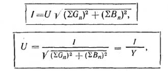
It must be remembered that the phenomenon represented by current resonance requires very competent and careful calculation of the resonant circuit. It is especially important to perform a correct and accurate calculation when there is a parallel connection, which will prevent the development of interference within the system. In order for the calculation to be correct, it is necessary to determine the power indicators of the electrical network. The average standard power that is dissipated under the conditions of a resonant circuit can be expressed in terms of rms current and voltage.
Under resonance conditions, the standard power factor is unity, and the calculation formula is:
Calculation formula
In order to correctly determine zero impedance under resonance conditions, you will need to use the standard formula:
Resonance curves
The resonance of the vibrational frequency is approximated by the following formula:
Resonance of the oscillatory circuit
In order to obtain the most accurate data from the formulas, it is recommended not to round off all values obtained during the calculation process. Some physicists calculate the values of the resonant circuit in accordance with the method of vector diagram of active current quantities. In this case, competent calculation and correct configuration of devices guarantees decent savings under the condition of alternating current.
Resonant circuits are used primarily to isolate a signal at the desired frequencies as a result of filtering other signals, so independent circuit calculations must be extremely accurate.
How to calculate correctly
Current resonance is very important to correctly calculate if there is a parallel connection to prevent interference around the system. For correct calculation, it is necessary to understand what power indicators are in the electrical network. The average standard power dissipated in a resonant circuit is expressed using RMS current and voltage. At resonance, the power coefficient is equal to unity and the formula looks like in the picture.
Calculation formula
To correctly determine zero impedance, you will need to use the standard formula given below.
Resonance curve formula
As for approximating the resonance of vibrational frequencies, this can be found out using the following formula.
Calculation of an oscillatory circuit
Note! To obtain the most accurate data using the given formulas, there is no need to round the data. This will result in a smart calculation that will result in decent AC savings when it comes to counting for lower bills.
In general, current resonance is what happens in part of a parallel oscillatory circuit when it is connected to a voltage source, the frequency of which may coincide with the circuit one. Occurs under conditions when a circuit having a parallel connection of a resistor coil and a capacitor is equal to the conductivity BL=BC. You can correctly make all the necessary calculations using a special formula or by resorting to the use of special measuring tools in the form of a multimeter.
Inductance and capacitance reactances
Inductance is the ability of a body to accumulate energy in a magnetic field. It is characterized by a phase lag between the current and the voltage. Typical inductive elements are chokes, coils, transformers, electric motors.
Capacitance refers to elements that accumulate energy using an electric field. Capacitive elements are characterized by a phase lag between voltage and current. Capacitive elements: capacitors, varicaps.
Their main properties are given; the nuances are not taken into account within the scope of this article.
In addition to the listed elements, others also have a certain inductance and capacitance, for example in electrical cables distributed along its length.
Operating principle of resonant currents
A visual representation of current resonance is given by an oscillatory circuit used in electronic circuits. It consists of a capacitor with capacitance C and a coil with inductance L, connected in parallel. In the process of transferring energy from the electric field of a capacitor to the magnetic field of an inductance, self-damping oscillations arise with a certain frequency. The occurrence of oscillations occurs due to active resistance R, which prevents the free passage of current.
The phenomenon of current resonance appears in a circuit where a capacitor and a coil are connected in parallel. Their ratings are selected in such a way that the currents flowing through C and L are equal. Therefore, in the C-L circuit the current will be higher than its value in the remaining sections of the circuit.
The operating principle of such a circuit is as follows. When power is applied, the capacitor accumulates a certain amount of charge equal to the rated voltage of the current source. After this, the source is turned off, and the capacitor is closed into the circuit circuit so that a discharge is sent to the coil. Current passes through it, thereby causing the generation of a magnetic field. As a result, an electromotive force of self-induction is created, directed towards the current.
The maximum value of the magnetic field is achieved when the capacitor is completely discharged. Thus, all the energy accumulated by the capacitor is transformed into a magnetic field of inductance. The charged particles continue to move due to the self-induction of the coil.
Since there is no longer a countercurrent from the discharged capacitor, it is recharged, but with a changed polarity. This causes the field of the coil to be converted into a charge on the capacitor and the whole process repeats. The active component R leads to a gradual decay of the oscillations. This is the main essence of resonance.
Operating principle
Current resonance can be seen in the inner surface of an electrical circuit that has a parallel coil, resistor and capacitor connection. The main principle of how a standard device works is not difficult to understand.
You may be interested in this Features of current operation
When the electrical power is turned on, charge accumulates inside the capacitor unit to the rated voltage. At this time, the power source is turned off and the circuit is closed into a circuit. This moment is accompanied by a transfer of the discharge to part of the coil. Next, the current readings that pass through the coil generate a magnetic field. An electromotive independent inductive force is created in the direction of the counter current. With a complete capacitor discharge, the current indicators increase as much as possible. The amount of energy becomes a magnetic induction field. As a result, this cycle is repeated, and the coil field is converted into a capacitor charge.
Principle of operation
Concept of resonance currents. Conditions for its occurrence and methods of implementation
Current resonance is a resonance that occurs in a parallel oscillating circuit when it is connected to a voltage source whose frequency coincides with the natural frequency of the circuit.
Current resonance condition: , .
B1 – reactive conductivity of the first branch,
It will be interesting➡ Instrumentation. Types and scope
B2 – reactive conductivity of the second branch.
A method of exciting oscillations in an electrical circuit, which consists in generating oscillations by regulating the signal that controls the excitation of oscillations.
Resonance of currents and its signs
The mode in which, in a circuit containing parallel branches with inductive and capacitive elements, the current of the unbranched section of the circuit is in phase with the voltage (φ = 0), is called current resonance.
Signs of current resonance:
The reactive components of the branch currents are equal to IPC = IPL and are in antiphase in the case when the input voltage is purely active;
The branch currents exceed the total circuit current, which has a minimum value and are in phase.
How to use
Resonant currents are used today in some filter systems, radio engineering, electricity, radio stations, asynchronous motors, high-precision electrical welding installations, oscillating generator electrical circuits and high-frequency devices. Often they are used to reduce the generator load.
Note! The simplest circuit where they are observed is a parallel oscillatory circuit. Such circuits are used in modern industrial induction boiler equipment and improve efficiency indicators.
Scope of application
Application in practice
Let's consider the benefits and harms of resonance of currents and voltages. The resonance phenomenon has brought the greatest benefit to radio transmitting equipment. In simple words, the receiver circuit has a coil and a capacitor connected to the antenna. By changing the inductance (for example, by moving the core) or the capacitance value (for example, with an air variable capacitor), you tune the resonant frequency. As a result, the voltage on the coil increases and the receiver catches a certain radio wave.
These phenomena can cause harm in electrical engineering, for example, on cable lines. The cable represents inductance and capacitance distributed along its length if voltage is applied to the long line in no-load mode (when there is no load connected at the end of the cable opposite the power source). Therefore, there is a danger that an insulation breakdown will occur; to avoid this, a load ballast is connected. Also, a similar situation can lead to failure of electronic components, measuring instruments and other electrical equipment - these are dangerous consequences of this phenomenon.
Practical application of voltage
Let's look at the beneficial and harmful properties of this phenomenon.
The effect of voltage resonance has brought undoubted benefits in radio electronics. A coil with a capacitor device connected to an antenna is mounted in the radio receiver circuit.
By moving the core, changing the induction, or the capacitive value using a capacitor, the resonance frequency is selected. As a result, the coil voltage increases, and the radio receiver detects a certain wave.
But for cables, this phenomenon is quite dangerous, since when voltage is applied to a cable that does not have a load, there is a possibility of the insulating sheath being shot through. To prevent this from happening, connect a ballast load.
The same situation leads to the breakdown of electronic parts, control and measurement devices and other electrical equipment.