The reliability of operation of TN electrical networks with a voltage class of up to 1 kV largely depends on the response parameters of protective equipment that disconnects the emergency section when overcurrents occur. There are several methods that allow you to check the reliability of the operation of circuit breakers; today we will consider in detail one of them - measuring the resistance of the phase-zero loop. To better understand the process, we will begin with a brief description of the terminology, after which we will move on to the electrical testing methodology using a special device MZC-300.
What is meant by a “phase-zero” circuit?
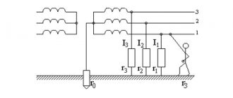
In systems with a solidly grounded neutral (you can read more about them in the article), when one of the phases comes into contact with the working zero or protective conductor PE, a phase-zero loop is formed, characteristic of a single-phase short circuit.
Like any electrical circuit, it has an internal resistance, the calculation of which allows us to determine the remaining significant parameters, in particular, the short-circuit current. Unfortunately, independent calculation of the resistance of such a circuit is associated with certain difficulties caused by the need to take into account many components, for example:
- The total value of all loop transient resistances arising in circuit breakers, fuses, switching equipment, etc.
- Movement of electric current in abnormal conditions. A loop can be formed both with a working zero and with grounded building structures.
In practice, it is not realistic to take into account all the listed components in calculations, which is why there is a need for electrical measurements. Special equipment allows you to obtain the necessary parameters automatically.
High precision instruments used
For phase measurements and calculations, both standard ammeters and voltmeters, the use of which is not difficult, or highly specialized instruments can be used. The latter ensure the highest possible accuracy of the obtained data on power grid parameters. The following measuring instruments are most widely used.
M417 is a reliable, proven device designed specifically for measuring resistance in a phase-zero circuit. One of the features of this device is the ability to carry out all work without removing the power, which greatly simplifies monitoring the state of the electrical network. This device uses the voltage drop method, ensuring the highest possible accuracy of the resulting calculations. It is allowed to use M417 in a circuit with a solidly grounded neutral and a voltage of 380 Volts. The only drawback to using this device is the need to calibrate the device before starting work.
MZC-300 is a new generation measuring device, which is based on a powerful microprocessor. The devices use a voltage drop method with a 10 ohm resistance connected. MZC-300 provides a measurement time of 0.03 seconds and can be used in networks with a voltage of 180-250 Volts. To ensure data accuracy, the device is connected to a distant point in the network, after which the Start button is pressed, and the result obtained is displayed on a small digital display. All calculations are performed by a microprocessor, which greatly simplifies phase control.
IFN-200 is a multifunctional device that allows you to perform phase measurements. The device operates with a voltage of 180-250 Volts. There are appropriate connectors to simplify connection to the network, and using this device does not present any difficulty. The limit on the measurement in the circuit is 1 kOhm, when exceeded, the protection is triggered and the device is turned off, preventing it from overloading. The device is based on a powerful microprocessor and has a built-in memory for the latest 35 calculations.
The need for measurements
Loop resistance is measured in the following cases:
- During commissioning, after repair, modernization or re-equipment of installations.
- Requirement from various control services, for example Oblenergo, Rostechnadzor, etc.
- According to the consumer.
During electrical measurements, certain parameters of the F-N loop are established, namely:
- Total circuit resistance, which includes:
electrical resistance of the transformer at the substation;
similar parameter of the linear conductor and working zero;
Numerous transient resistances formed in switching equipment, for example in protective devices (AV, RCD, differential circuit breakers), starters, manual switches, etc. Also influenced by the cross-section of conductors, cable insulation, grounding of the transformer neutral, parameters of the RCD or other protection of electrical installations.
- Short circuit current (ISC). In principle, it can be calculated using the formula: ISC = UН / ZП, where UН is the nominal voltage level in the electrical network, and ZP is the total loop resistance. Considering that protective devices during a short circuit must automatically turn off the power according to established temporary standards, the following condition must be met: ZП*IAB <= UН. In this case, IAB is the current at which the AV or other protection device is triggered; its value must be inferior to ISC.
Before describing detailed measurement techniques, it is necessary to briefly describe the instrument that will be used in the process - the MZC-300. We chose this device because it is most often used by measurement laboratories.
Formulas for calculation
After taking measurements and recording the results in a protocol in the established form, it is necessary to carry out some calculations that will allow you to check the performance of the RCD and cable lines. Calculations are reduced to the use of standard electrical formulas, in accordance with the PUE:
- Phase-zero loop resistance formula:
Z = ZS + ZT / 3,
Z – the required value of the resistance of the phase-zero loop,
ZS is the total resistance of all cable cores included in the circuit,
ZT is the resistance of the transformer connected to the circuit.
- Expected current strength of the onset of a single-phase short circuit:
IKZ = UФ / Z,
IKZ – the required value,
UФ – rated voltage on the phase cable,
Z – phase-zero loop resistance value, determined by the formula given below.
- The protective automatic shutdown time of the RCD is a tabular value and should not exceed the following values:
UФ = 127 V, TNprev = 0.8 s,
UФ = 220 V, TNprev = 0.4 s,
UФ = 380 V, TNprev = 0.2 s,
UФ more than 380 V, TNprev = 0.1 s,
TNpre is the maximum permissible response time of the protective automatic shutdown of the RCD.
- Total ultimate resistance of the conductor providing protective shutdown of the RCD:
ZП = 50 Z/UФ,
50 is a constant characterizing the reduction in the rated voltage in the conductor in the section of the circuit between the grounding cable and the panel where the RCD is installed.
- Short circuit current, upon reaching which an automatic emergency shutdown occurs:
IKZ fact = UФ / ZП.
From the above formulas it is clear that the dependence of the calculation of each indicator is derived from the standard Ohm’s law in canonical form. Numerical values of the characteristics are taken based on the results of measurements taken, or determined from the tables given above. The phase-zero loop resistance formula is the main calculated value
Reading received information
Regardless of the type, model and modification of the device, the indicators are read from the interactive liquid crystal display after pressing the “Start” or “Test” button.
More expensive versions of the equipment are equipped with a large multi-line display, which displays all the necessary data at once. If the device has a small built-in display, the information on it is not completely displayed. To obtain all the information, you need to scroll through the screen by pressing the “Sel” or “Z/L” keys.
Some devices in the higher price category are equipped with a memory function for the last few settings, usually from 5 to 35 positions. This greatly simplifies the work of specialists at a large facility. Entering each measurement into the device’s memory allows you to postpone drawing up a protocol until the desk processing of full-scale tests of the electrical network begins.
Analysis of measurement results and preparation of the measurement protocol form
Based on the measurement results, the information obtained is entered into a protocol in the established form. This document is certified by an expert who has the necessary qualifications and clearance, after which it enters into legal force and is attached to the general folder for delivery of the object. The protocol contains the following information:
- Information about the company that carried out the measurements.
- Serial number, title and date of preparation of the paper.
- Official information about the test customer.
- Data justifying the need for measurements. This column indicates the purpose for which the work was carried out - acceptance of the facility into operation, periodic inspection, or testing after repair and replacement of electrical installations.
- Information about the climatic parameters in the room where the measurements were taken. If the test was carried out in relation to an external cable line, the parameters of the outside air on the day of testing are indicated.
- A table with measurement results, designed in accordance with the requirements of the PUE.
- Information about the instruments used during the tests, indicating the date of their verification.
- Conclusions of the expert commission.
The test report confirms the safe operation of the cable network and electrical equipment. When issuing a positive conclusion, the responsible person puts a personal signature, and a company representative certifies the paper with a blue seal, which indicates the responsibility assigned to the company.
Sample test report
Protocol No. ___
Checking the coordination of phase-zero circuit parameters with the characteristics of circuit breakers and the integrity of protective conductors
Climatic parameters, as of the date of testing
Air temperature ___ oC, Relative humidity __%, Atmospheric pressure ___ mm Hg. Art.
Purpose of measurements:
Regulatory technical documentation for compliance with which tests were carried out:
- Measurement results
| No. Pos. | Tested section of the circuit, installation location of the circuit breaker | Overcurrent protection device | Measured value of phase-zero circuit resistance, Ohm | Measured (calculated) value of single-phase fault current, A | Circuit breaker response time, sec. | ||||||||
| Typical designation | Trip type | Nom. current | Range current triggered release short short circuit | A | IN | WITH | A | IN | WITH | Maksim. permissible | According to the time-current characteristic | ||
| 1 | 2 | 3 | 4 | 5 | 6 | 7 | 8 | 9 | 10 | 11 | 12 | 13 | 14 |
| Power shield, No. 1 | |||||||||||||
| 1 | Group No. 1 | VA6730 | WITH | 10 | 50 – 100 | 0,6 | 366 | 0,4 | 0,01 | ||||
| 2 | Group No. 2 | VA6730 | WITH | 10 | 50 – 100 | 0,5 | 440 | 0,4 | 0,01 | ||||
| 3 | Group No. 3 | VA6730 | WITH | 16 | 80 – 160 | 0,4 | 550 | 0,4 | 0,01 | ||||
| 4 | Group No. 4 | VA6730 | WITH | 25 | 125–250 | 0,5 | 440 | 440 | 0,4 | 0,01 | |||
| 5 | Group No. 5 | VA6730 | WITH | 16 | 80 – 160 | 0,5 | 0,4 | 0,01 |
Conclusion: The parameters of the phase-zero circuit comply with the requirements of the PUE, clause No. 3.1.8, clause No. 1.7.79
The measurements were carried out:
Leading engineer EIL: Avilov / Avilov A. Yu.
Engineer EIL: Ivanov / Ivanov S. O.
The protocol was checked and approved by:
Head of EIL: Kochetkov / Kochetkov M. A.
Date __. __.____
Brief description of MZC-300
Let's look at the appearance and main elements of the MZC-300 meter.
Location of the main elements of the MZC-300 device
Designations:
- Information display. A full description of its fields can be found in the user manual.
- "Start" button. Starts the following measurement processes:
- ZP, recall, is the total resistance of the F-N circuit.
- ISC – expected short-circuit current.
- Active resistance is necessary for calibrating the device.
The start of each measurement is accompanied by a characteristic sound signal.
- SEL button. Serves for sequential display of all loop characteristics obtained as a result of the last measurement on the information display. In particular, the following information is displayed:
- ZP parameters.
- Expected IKZ.
- Level of active and reactive resistance (R and X).
- Phase angle ϕ.
- Z/I button. At the end of the test, switches the display of characteristics between the expected ISC and ZP.
- Button to disable/enable the measuring device. If, when starting the device, you press “SEL” simultaneously with this button, the meter will go into auto-calibration mode. Its detailed description can be found in the user manual.
- Connector for connecting a probe in contact with the working zero, PE or PEN conductor. The corresponding designation is marked on the body of the device.
- Connector for a probe connected to one of the phase wires. As a rule, marked with the letter “L”.
- Like the i connector, unlike the test lead sockets, it is used only in automatic calibration mode. On the device body they are designated as “K1” and “K2”.
Protocol on measurements of the “phase zero” circuit
Based on the measurements taken, a special protocol is drawn up. It is used to store recorded readings, as well as to carry out comparative analysis with subsequent tests.
The protocol displays the following information:
- the date of the;
- protocol number;
- purpose of testing;
- information about the organization conducting the tests;
- information about the customer;
- current climatic conditions: atmospheric pressure, temperature and humidity;
- measurement range, accuracy class and type of release;
- meter used for testing;
- recorded readings;
- test result;
- positions, names and signatures of the persons who carried out the measurements and checked the protocol.
Preparatory stage
Almost all methods of measuring the phase-zero circuit do not allow obtaining accurate information about such characteristics as ZP and ISC. This is due to the fact that the vector nature of voltage is not taken into account. Simply put, simplified short circuit conditions are taken into account. When testing electrical installations, such approximation is allowed only in cases where the level of reactance does not have a significant effect.
Before you begin measuring the characteristics of the F-N loop, you should first carry out a number of preliminary tests. In particular, check the continuity and resistance level of the protective lines. After this, measure the resistance between the ground loop and the main metal elements of the building structure.
What to do if the measured short-circuit current is too low?
Let's say we measured it with a device and got the value of the short-circuit current in the socket (as a rule, the measurement is carried out at the most remote point). How can you tell if this current is too low? This is assessed by the criterion of guaranteed operation of the electromagnetic release of the circuit breaker in the measured circuit. It is logical that for this the short-circuit current must be greater than the upper limit of the tripping range. Let me remind you that for characteristic “B” the spread is 3…5 In, for “C” – 5…10 In, for “D” – 10…20 In. To be more precise, let’s turn to the PUE (clause 7.3.139):
7.3.139. In electrical installations up to 1 kV with a solidly grounded neutral, in order to ensure automatic shutdown of the emergency section, the conductivity of the neutral protective conductors must be selected such that, in the event of a short circuit to the housing or neutral protective conductor, a short-circuit current occurs that is at least 4 times greater than the rated current of the fuse link of the nearest fuse and at least 6 times the current of the circuit breaker release, which has an inverse current characteristic.
When protecting networks with automatic circuit breakers that have only an electromagnetic release (without a time delay), you should be guided by the requirements regarding the short-circuit current multiplicity and given in 1.7.79.
As I understand it, the first part of 7.3.139 only talks about the thermal release - its rated current must be at least 6 times less than the short-circuit current. The second part of this paragraph, as well as paragraph 1.7.79, talks about the maximum shutdown time during a short circuit (0.4 s), which must be provided only by an electromagnetic release. At the same time, it is not clearly indicated on the choice of AV taking into account its shutdown characteristics.
Because of this vagueness of the wording, they use the rule set out in PTEEP (checking the operation of protection in a power system with a grounded neutral, clause 28.4), which states that when a short circuit to the neutral protective conductor occurs, the short-circuit current must be at least “1.1 the upper value of the operating current of the instantaneous release.”
That is, for a B10 circuit breaker, the short-circuit current at the end of the line that it protects must be at least 10x5x1.1 = 55 A. If a C25 circuit breaker is installed, the short-circuit current must be at least 25x10x1.1 = 275 A.
If the short-circuit current is less, the permissible response time is by no means guaranteed. What to do? There are two ways out:
- increase the short-circuit current, this requires the cost of laying a new supply line (at least its weakest link),
- reduce the rating of the machine (for example, 25 A to 16) and the letter of the shutdown characteristic (from “C” to “B”) to the detriment of the maximum load power.
Measurement procedure using MZC-300
Before proceeding directly to the tests, we will briefly describe the adopted procedure, it includes:
- Compliance with certain conditions that ensure the necessary accuracy.
- Selecting a device connection method.
- Obtaining information about the network voltage.
- Measuring the main characteristics of the F-N loop.
- Reading the received information.
Let's look at each of the stages listed above.
Compliance with certain conditions
Some features of the meter should be taken into account:
- The device will not allow testing if the rated network voltage exceeds the maximum value (250V). Exceeding the measurement range (250.0 V) will result in an “OFL” warning being displayed on the device screen, accompanied by a long sound of the buzzer. In this case, the device should be turned off and disconnected from the loop being measured.
- If the neutral or protective conductors are broken, an error in the form of the “—” symbol will be displayed on the device screen, accompanied by a long buzzer signal.
- The voltage level in the loop being measured is insufficient for testing, usually if it is below 180.0 volts. In this case, the screen will display an error with the symbol “U”, accompanied by two beeps.
- Thermal blocking of the device is triggered. In this case, the “T” symbol is displayed on the screen, and the buzzer gives two long beeps.
Selecting a device connection method
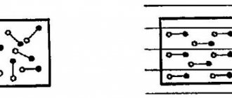
Let's consider several options for electrical connection diagrams of the device for testing:
- Removing characteristics from the “F-N” loop; in the example shown in the figure, the parameters in the C-N circuit are measured.
C-N loop test - Measurement in a loop between one of the phases and the PE conductor.
C-PE loop test - Measurements in CT circuits.
Connecting the device in circuits with protective grounding
- To check the reliability of grounding of electrical equipment, the connection method given below is used.
Testing the reliability of grounding of electrical equipment enclosures
Important! Regardless of the method of connecting the device, you must ensure that the wires are connected securely.
Obtaining information about the network voltage
The device we are considering allows you to measure UH within the range from 0 to 250.0 volts. The phase voltage is displayed on the device display immediately after pressing the power button or after five seconds, after testing (if the control buttons responsible for displaying the results on the screen were not pressed).
Measuring the main characteristics of the F-N loop
The method for measuring ZP in a loop, used in the MZC model range, is based on creating an artificial short circuit using a limiting resistance (10.0 Ohm), which reduces the value of the ISC. After testing, the microprocessor of the device calculates ZP, highlighting reactive and active components. The measurement procedure does not exceed 30.0 ms.
It is characteristic that the device automatically selects the desired range for measuring ZP. When you press the “Z/I” button, the display alternately displays such basic characteristics of the loop as expected short-circuit current (ISC) and total resistance (ZP).
It should be taken into account that when calculating, the microprocessor sets the UH value at 220.0 volts, while the current rated voltage may differ from the calculated one. Therefore, to increase the accuracy of electrical circuit measurements, a correction should be made. For example, with a real UH equal to 240.0 V, the correction to reduce the instrument error will be equal to 1.09 (that is, it is necessary to divide 240 by 220).
The process of measuring loop characteristics is started by the “Start” button.
Important! Tests carried out using instruments from the MZC range are almost guaranteed to trigger the RCD. To avoid this, it is necessary to first bypass the residual current devices. After taking measurements, do not forget to remove the shunt from the RCD.
Reading received information
As mentioned above, tests begin after pressing the “Start” button. After completing the measurements, the characteristics of the “F-N” loop are displayed on the screen, depending on the settings. You can scroll through the information displayed on the display using the “SEL” and “Z/I” buttons.
Please note that the MZC-300 only displays the results of the last measurement. If it is necessary to store the results of all tests in electronic memory, you will need a device with advanced capabilities, for example the MZC-303E device.
MZC-303E device for measuring the characteristics of the F-N loop
Such a device allows you not only to store information about all measurements in electronic memory, but also, if necessary, transfer it to a computer using a USB interface.
How the network is measured
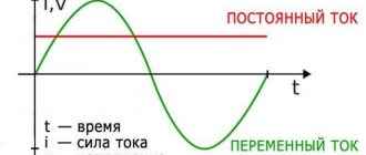
To understand this, it is necessary to consider a circuit in which there is a consumer connected through a regular outlet. So, as mentioned above, phase and zero are supplied to the socket. In this case, there is a loss of voltage up to the outlet due to the resistance of the main cables and wires. This has been known for a long time; this process is described by Ohm’s formula:
R=U/I.
True, this formula describes the relationship between the magnitudes of direct electric current. To convert it to alternating current, you will have to take into account some indicators:
- Active component of network resistance.
- Reactive, consisting of a capacitive and inductive part.
What does it mean?
It is necessary to understand that the electromotive force that appears in the windings of the transformer forms an electric current. It loses its voltage when passing through the consumer and the supply wires. In this case, the current itself overcomes several types of resistance:
Read also: How to make curls using foam?
- Active is a consumer and wires. This is the biggest piece of resistance.
- Inductive is the resistance of the built-in windings.
- Capacitive is the resistance of individual elements.
How to measure resistance loop phase zero
To calculate the total resistance of the network (phase and zero loop), it is necessary to determine the electromotive force that is created on the windings of the transformer. True, they won’t let you into the substation without special permission, so measuring the phase-zero loop will have to be done in the outlet itself. Please note that the outlet should not be loaded. Then you need to measure the voltage under load. To do this, plug any device into an outlet, it can even be an ordinary incandescent light bulb. Voltage and current are measured.
Attention! The load on the outlet must be stable during the measurement process. This is the first one. Secondly, the best option is considered if the current in the circuit is from 10 to 20 amperes. Otherwise, defects in the network section may not appear.
Now, using Ohm's law, you can determine the total resistance of the loop. In this case, you will have to take into account that the voltage (measured) in the outlet may deviate from the nominal voltage with or without load. Therefore, you first need to calculate the resistance at different voltage values. It is clear that under load the voltage will be greater, so the loop impedance is the difference between two resistances:
Rп=R2-R1, where R2 is the loop resistance under load, R1 – without it.
Read also: Sonata-symphonic cycle
As for accurate measurements. This can be done with homemade devices, there are no problems here, but the accuracy of the measurements in this case will be very low. Therefore, it is recommended to use voltmeters and ammeters with high accuracy (class 0.2) for this process.
Measuring process loop phase zero
Although we must pay tribute to the market, today such devices can be purchased freely. They are not cheap, but for a professional it is a necessary thing.
Features of the circuit breaker
The design of the device and the principles of operation of this protection are described in a separate article. I recommend checking it out.
The circuit breaker is designed to quickly remove voltage from the power circuit in the event of an overload or a short circuit.
Overload mode
The initial protection of the electrical circuit was previously carried out using a fuse, the fuse of which simply burned out and broke the electrical circuit under the thermal influence of the emergency current.
This function remains in the design of the circuit breaker. In it, it is implemented by a thermal release and provides overload protection, removing voltage from the protected area with a time delay. This is necessary to eliminate frequent shutdowns when transient processes occur from various switching circuits.
It is convenient to determine the operating area of the thermal release, as well as its second component, the shutdown electromagnet, using the time-current characteristic, which indicates the dependence of the response time on the magnitude of the emergency current passing through the contacts of the bimetallic plate.
Short circuit mode
When it occurs, the maximum possible power is applied to the circuit, the energy of which can melt metal wires or cause a fire. Therefore, in order to preserve the equipment, it is necessary to perform very fast power removal in thousandths of a second.
This is the task of the second component of circuit breaker protection: current cutoff, which is performed by an electromagnetic release.
Both machine protections operate autonomously, do not depend on each other, and have their own settings and settings. However, they are selected for a specific value of the operating rated current and are designed to ensure its normal passage without unnecessary, false shutdowns.
The principle of selecting a circuit breaker
When determining its technical capabilities, the following are taken into account:
- the value of the rated current in the network, which is significantly influenced by the condition of the electrical wiring and the loads connected to it;
- permissible overload mode;
- disconnecting capacities of possible emergency modes.
The algorithm for selecting a circuit breaker based on rated current, taking into account the features of the power supply circuit, is shown in the diagram.
It allows you to make a preliminary calculation of the necessary parameters of the circuit breaker and select its protective characteristics.
To carry out such a calculation, you can also use the Electric 7-8 computer program.
Examples of calculations
Two methods are considered as examples of such measurements.
Effect of voltage drop on the controlled section of the power circuit
When describing this method, it is important to pay attention to the difficulties of its practical implementation. This is because several steps are required to obtain the final result. First you will have to measure the network parameters in two modes: with the load disconnected and connected
First you will have to measure the network parameters in two modes: with the load disconnected and connected
In each of these cases, resistance is measured by taking current and voltage readings. Next, it is calculated using classical formulas arising from Ohm’s law (Zп=U/I)
First you will have to measure the network parameters in two modes: with the load disconnected and connected. In each of these cases, resistance is measured by taking current and voltage readings. Next, it is calculated using classical formulas resulting from Ohm’s law (Zп=U/I).
In the numerator of this formula, U represents the difference between two voltages - when the load is on and when the load is off (U1 and U2). The current is taken into account only for the first case. To obtain correct results, the difference between U1 and U2 must be large enough.
The impedance takes into account the impedance of the transformer coil (it is summed with the result obtained).
Application of an independent power supply
This approach involves determining the parameter of interest to specialists using an independent source of supply voltage. When carrying it out, you will need to take into account the following important points:
- During the measurement process, the primary winding of the station supply transformer is short-circuited.
- From an independent source, the supply voltage is supplied directly to the short-circuit zone.
- Phase-zero resistance is calculated using the already familiar formula Zп=U/I, where: Zп is the value of the desired parameter in Ohms, U is the measured test voltage in Volts, I is the value of the measuring current in Amperes.
All the methods considered do not claim absolute accuracy of the results obtained from them. They provide only an approximate estimate of the impedance value of the phase-zero loop. This nature of it is explained by the impossibility, within the framework of the proposed methods, of measuring inductive and capacitive losses, which are always present in power circuits with distributed parameters. If it is necessary to take into account the vector nature of the measured quantities (phase shifts, in particular), special corrections will have to be introduced.
Safety precautions
Tests are allowed to be carried out by workers over 18 years of age who have received all types of safety training. When taking measurements, the team must have 2 people, one of whom has an ES clearance group of at least III.
Safety regulations:
- the work site is fenced;
- work in rubber shoes or stand on a dielectric mat;
- wear rubber gloves; short or rolled up sleeves of overalls are not allowed;
- the handles of the tool must be insulated;
- cannot be measured at air temperatures below +5°C.
After work, they disassemble the measuring circuit, collect the wires, hand over the inspection site to the permitting person, and report to the authorities about the identified malfunctions.