Main types of electromagnetic relays
The main purpose of these devices is switching at high load currents. In other words, they perform the functions of switches that, through weak currents, turn on circuits with high currents. If such a circuit is connected directly without a relay, then the wiring and button simply will not withstand high currents and will melt. The relay takes on a large current load and makes switching using powerful contacts.
Electromagnetic switches are divided into two main groups:
- Neutral relays have the simplest design. It includes a contact and magnetic system. Each contact group includes two fixed and one common moving contact. The magnetic system consists of a movable armature, a core, a winding and a yoke.
- A polarized relay consists of the same systems. However, the magnetic system contains two cores with windings, as well as a contact rod and a permanent magnet.
Unlike neutral ones, electromagnetic polarized devices are able to operate depending on the polarity of the control signal. Electrical sheet steel is used to make the core, which can significantly increase the speed of operation of the device.
RP-3, 4, 5, 7
Polarized relays type RP-4, 5, 7
Purpose
Polarized relays of types RP-3, RP-4, RP-4M, RP-5 and RP-7 are designed for switching electrical circuits in automation equipment, communications (in the receiving and transmitting circuits of voice-frequency telegraph equipment) and signaling. The relay is also used as part of relay protection and automation devices as highly sensitive and high-speed elements.
Developer and manufacturers: Polarized relays of the RP-3, RP-4 (RP-4M), RP-5, RP-7 types were developed in the early 50s at OKB-3 of the Krasnaya Zarya plant, where their serial production was established production. The relays were copied from large polarized relays installed in the V-2 missile control system. Polarized relays RPS-11/3, RPS-11/4, RPS-11/5, RPS-11/7, developed in 1957 by the same OKB-3, became more miniature analogues of these relays. Subsequently, the production of the relay was transferred to the Ufa telephone equipment plant, as well as to Starodubsky, which initially mastered the production of silumin casting of the supporting body of the RP-3, RP-4, RP-5 and RP-7 relays and supplied this part to both Krasnaya Zarya and Ufa plant of telephone equipment, but then at the Starodub plant they mastered the production of the entire relays themselves. Polarized relays RP-3, RP-4 (RP-4M), RP-5, RP-7 were produced in accordance with the technical specifications RS0.452.020 TU and the general technical specifications RKh0.074.005 TU.
Equipment (equipment) in which the relay was used
Relay protection and automation devices: RIS-E3M – RP-4 relay; KRS-4, DZ-2, DFZ-201, DFZ-504, DFZ-401, DFZ-402, DZL-1, KRB-125, KRB-126 – relay RP-7; ………………….
Design and principle of operation
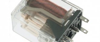
Polarized relays of the RP type are made in the shape of a parallelepiped and were produced in several modifications: RP-3, RP-4 (RP-4M), RP-5, RP-7. All internal elements of the relay are mounted on a supporting body made of silumin. To prevent dust and small steel filings from entering the internal elements of the relay (the permanent magnet field of the relay has great strength), a casing is placed on top of them, which is held on the supporting body with two screws, while in earlier relays one of the screws was inserted through a sealing cup , later they began to simply paint the outside of the screws. Relay casings were most often made of unpainted aluminum. Sometimes powder coated in gray. For polarized relays RP-7, which were most often used in relay protection and automation devices, in addition to aluminum, black plastic casings with a glass window and transparent plastic casings were also made, which made it possible to observe the relay contact systems without removing the casings. The casings were usually marked with the year of manufacture, the manufacturer's logo and service marks.
Figure 1. General view of polarized relays of the RP type: a – relays RP-3, RP-4, RP-4M; b – relay RP-5; c – relay RP-7.
The terminals of the windings and contacts of the relay contact system are soldered to 16 flat contact pins (lamellas) of a special phenolic plug block. This block is attached with two screws and two guide pins to the supporting body. The block bears the decimal number of the relay (passport), its type and logo (trademark) of the manufacturer, as well as the numbering of the terminals. The relay is connected to the power supply and switched circuits using a connecting (plug) block type SK, which allows for quick replacement of the relay. To remove the relay from the block, there is a special loop on the casing. One of the guide pins for each type of relay acts as a key; it has a bevel on one side and for each type this bevel is turned in its own direction. On the connecting block for each type of relay there is a mating part, a metal plate (see Figure 2). Thanks to this design, each type of relay fits only into its own connecting block, this allows you to avoid mistakes when installing the relay. External wires are connected to the connecting block by soldering. The connection block is secured to the equipment chassis using two screws.
Figure 2. General view of connecting blocks of the SK type for polarized relays of the RP type (view from the side where the relay is installed in the block): a – RSZ.656.009 Sp for relays RP-3, RS3.656.055 Sp for relays RP-4 and RPB-4, RS3.656.092 Sp for relay RP-4M, RS3.656.065 Sp for relay 64P; b – RS3.656.056 Sp for relays RP-5 and RPB-5; c – RS3.656.057 Sp for relays RP-7 and RPB-7, RSZ.656.000 Sp for relay OR65.
Inside, the design of all modifications of the RP relay is almost the same. They differ in the adjustment of the contact system, winding data and some minor details. The same design is used for polarized relays of type 64P and OR65. Relays of types RP-3 and RP-4 (RP-4M) are two-position, bistable, they have neutral adjustment with magnetic armature locking. The contacts are installed symmetrically relative to the neutral. When the current is switched on and off, the relay armature is held at the pole to which it was attracted. A relay of type RP-3 differs from a relay of type RP-4 in less sensitivity, greater pressure in the contacts in the absence of current in the winding due to a thinner armature suspension spring. The RP-4M relay has a fluoroplastic gasket between the armature springs. The gasket is designed to reduce anchor rattling. Relay type RP-5 is three-position, single-stable. In the absence of excitation, the relay armature is in the middle position and does not touch the contacts. Relay type RP-5 differs from relay type RP-4 in the larger thickness of the armature suspension spring. Relay type RP-7 is a two-position, single-stable with predominance. Both contacts are located on the same side of the neutral. In the absence of current in the winding, the armature of the RP-7 type relay is always pressed to the right contact. Depending on the number of windings, depending on the passport, polarized relays RP were produced: - RP-3 seven-winding; — RP-4 two-winding, three-winding, seven-winding; — RP-5 single-winding, double-winding, three-winding, four-winding, five-winding, six-winding and seven-winding; — RP-7 single-winding, double-winding, three-winding, four-winding, five-winding and seven-winding. The contacts of polarized RP relays have a spherical contact surface. The contact material, depending on the passport and year of manufacture, can be: Pli-10, Sr999, PdTsrKh-1, VS-70, ZlNk95-5. Polarized relays RP consist of the following parts (see Figure 3): a permanent magnet 1, a coil with windings 2 with a horseshoe-shaped magnetic circuit 3, an armature 4, a tongue with movable contacts 5 and two fixed contacts 6. One of the poles of a permanent magnet is embedded in the carrier the body is made of non-magnetic material, two studs with curly nuts 7 are screwed in, securing the ends of the horseshoe-shaped magnetic circuit to the relay body. At the ends of the magnetic circuit there are thickenings 8 that form the pole extensions of the permanent magnet. The magnetic core is made of permalloy, which ensures high sensitivity of the relay. The relay armature, made of mild steel, is suspended from the frame 9 on a flat steel spring 10, replacing the axis. In the upper part of the armature there are wings 11, located in the assembled relay above the second pole of the permanent magnet. Tongue 5, on which the movable contacts are mounted, consists of two springs riveted to the armature. When the relay operates when the moving contact hits the stationary one, one spring slides with a certain friction along the other, thereby reducing the vibration of the contacts. For the same purpose, the fixed contacts 6 are also mounted on flat springs that rest against the adjusting screws 12, secured with locking screws 16. The current is supplied to the movable contacts through the frame and the spring on which the armature is connected. Both fixed contacts and the frame with the armature are mounted on a porcelain block 13, attached with two screws 14 to the relay body. Thanks to this, the frame and armature are isolated from the relay body. On the lower part of the armature, on both sides there are two cylindrical pads 15 made of insulating material that prevent the armature from coming into contact with the magnetic circuit.
Figure 3. Design of a polarized relay of the RP type: 1 – permanent magnet; 2 – relay coil; 3 – magnetic circuit; 4 – anchor, 5 – tongue with movable contacts; 6 – fixed contacts; 7 – studs with figured nuts; 8 – pole extension; 9 – frame; 10 – flat spring; 11 – wings; 12 – adjusting screws; 13 – porcelain block; 14 – screws securing the block; 15 – insulating cylindrical linings; 16 – locking screws; 17 – screws with which the frame is attached to the block.
Operating principle of polarized relays RP
When a positive potential is applied from a current source to the beginning of the winding and a negative potential to the end of the winding, the relay armature closes with the right relay contact. When the current in the winding is in the opposite direction, the armature closes with the left contact. From the N pole of the permanent magnet, through two pins and pole extensions, the magnetic flux, passing through two air gaps, enters the armature on both sides. Having passed through it, the flow passes into the wings located in the upper part of the armature, and through the air gap closes on the S pole of the magnet. In turn, the magnetic flux created by the current; flowing through the relay winding, circulates through a circuit consisting of a horseshoe-shaped magnetic circuit with pole extensions and an air gap, penetrating the lower part of the armature located in this gap. If the relay armature is installed along the center line of the OM, then such a symmetrical arrangement will cause the magnetic flux of the permanent magnet in the air gap between each of the pole extensions and the lower part of the armature to be divided into two equal parts Fo/2. In this position, two equal and oppositely directed forces F1 and F2 will act on the anchor, as a result of which the anchor will be in a position of equilibrium. But this equilibrium is unstable, since the slightest asymmetry or external push can remove the armature from its average position (along the OM line), and it will move towards the nearest end of the magnetic circuit, say, clockwise, until the tongue stops in a fixed contact. Due to the fact that the lower part of the armature will in this case be closer to the left end of the magnetic circuit, the flux between them will be greater than the flux between the armature and the right end of the magnetic circuit, accordingly, through force F1 it will become greater than force F2, and as a result the armature will be pressed to the right contact by force F = F1 - F2. If the anchor is deflected at the same angle counterclockwise from the neutral line, then with the same force F = F2 - F1 the anchor will be pressed to the left contact. When current flows through the relay winding, an additional magnetic flux Фi appears in the horseshoe-shaped magnetic circuit, which interacts between the ends of the magnetic circuit in the air gap with the flux of a permanent magnet. As a result, the total flux on the left side of the anchor increases, and on the right side it decreases, and the anchor will move clockwise under the action of the resulting force.
Figure 4. Schematic diagram of the magnetic circuits of a polarized relay of the RP type
Adjustment of polarized relays of the RP type All polarized relays of the RP type are adjusted at the factory, so special adjustment is not required in operation. In cases of violation of adjustment and non-compliance with technical requirements, it is necessary to readjust the relay. Most simply, within small limits, the actuation and return currents of the relay can be adjusted by turning the stop screws of the 12 fixed contacts. So, to increase the relay operating current, the thrust screw 12 of the left fixed contact is unscrewed, and to decrease it, it is screwed in. To increase the relay return current, the stop screw of the right fixed contact is screwed in, and to decrease it, it is screwed out. In cases where the specified adjustment does not give the desired results, it is necessary to make a more complex adjustment according to the instructions given below: a) loosen the tightening of the nuts 7 securing the magnetic circuit. The gap between the poles of the magnetic circuit increases to the maximum possible, after which the nuts are again securely tightened. The gap is increased by pushing the ends of the magnetic circuit apart with a screwdriver inserted into the air gap between its ends. The gap must be increased carefully so as not to damage the armature and the spring securing it; b) the maximum possible distance between the moving contacts is established; c) the porcelain block is installed in such a position that when a current flows 5-7% more than the operating current, the armature is separated from the right pole extension of the magnet, after which the screws securing the block are slightly tightened; d) precise adjustment of the relay to a given operating current is carried out by turning the stop screw 12 of the left fixed contact. In case of unclear operation of the relay, when the armature, coming off the right pole, does not reach the left pole, but remains in an intermediate position (the armature “floats”), the gap between the poles of the magnetic circuit should be slightly reduced (usually it is enough to bring the left end of the magnetic circuit closer) and make an adjustment relay again; e) after the relay is activated, screw 12 of the right fixed contact is screwed in until the NO contact is reliably closed. At the same time, the relay return coefficient is checked: if the relay return coefficient is lower than the required one, then it must be increased to the required or greater value by screwing in the stop screw 12 of the right fixed contact. In this case, you need to ensure that a sufficient amount of pressure is provided on the fixed right contact of the relay; f) check the size of the gap between the contacts. If the gap value is less than permissible, it is necessary to adjust the relay again; g) screws 14 and locking screws 16 are securely tightened, after which the magnitude of the relay operation and return currents is re-checked. By changing the position of the armature in the air gap by moving the porcelain block, you can adjust the relay to neutral, that is, when the armature is located along the center line, or to dominance, when the armature is pressed to one of the fixed contacts. The operating position of the relay is any.
Brief technical specifications
Input parameters: Operation current: 0.029 - 33 mA depending on the passport Output parameters: Current switched by contacts: 0.2 A Voltage on open contacts: no more than 27 V Dimensions: 98.7 x 27.5 x 42.6 mm (V x W x D) without connecting block Weight: no more than 220 g.
Additional information (sources of information)
1. Northern dawn 1974-2014. Preserving the past, creating the present and the future. (Corporate publication of OJSC NPK "Northern Zarya") Author: Malashchenko A.A. St. Petersburg, 2014 2. Calculation of electromagnetic relays for automation and communication equipment. Third edition revised and expanded. Author: M.I. Witemberg. M-L.: Energy, 1961. 16-3. Polarized relays of RP types. Pages 479-481. Description of the RP relay (DjVu, 93 kB.) 3. Handbook of electromagnetic relays. Iglovsky I.G. and Vladimirov G.V.-L.: Energy, 1975 4. Handbook of low-current electrical relays. Second edition, revised and expanded. Iglovsky I. G. and Vladimirov G. V. - L.: Energoatomizdat, 1984 5. Handbook of low-current electrical relays. Third edition, revised and expanded. Iglovsky I. G. and Vladimirov G. V. - L.: Energoatomizdat, 1990 6. Directory. Relays and contactors. Design Bureau, 1962. Polarized relays RP-4. RP-4M, RP-5 and RP-7. Relay description and technical data. (DjVu, 572 kB.) 7. Directory. Relays and contactors. Design Bureau, 1962. Block for relays RP-3, RP-4, RP-5 and RP-7. (DjVu, 63 kB.) 8. Some old passports (Uhhhhhhhh) relays RP-4, RP-5, RP-7 can be viewed in the information sheet from the Radio magazine >> go9. Handbook on elements of automation and telemechanics. Electromagnetic relays. I. E. Decabrun and N. R. Teder. Edited by B. S. Sotskov. Conversion tables for relays from the Krasnaya Zarya plant. M.-L.: SEI, 1958 10. Setup and operation of the relay part of differential-phase high-frequency protection of 400 - 500 kV lines (DFZ-401 and DF3-402). V. V. Kochetov, E. D. Sapir and G. G. Yakubson. Adjustment of relay RP-7. M.-L.: SEI, 1962 11. Guidelines for setting up, checking and operating longitudinal line protection of the DZL- type. Ya. M. Smoryadinsky, V. M. Volkov. Adjustment of relay RP-7. M.-L.: SEI, 1962 12. Polarized relay type RP-7. Technical description and operating instructions. OBK 469.349. Edition 16 13. Industry standard OST4 G0.452.017. Revision 1-72. Polarized relays type RP-4, RP-4M, RP-5, RP-7. Selection guide 14. Industry standard OST4 G0.452.015. Revision 1-72. Polarized relay type RP-3. Selection guide 15. Industry standard OST4 G0.365.001. Revision 1-72. Connecting blocks type SK. Selection Guide
Mechanical characteristics of relay type PMPUSH – 150/150.
LABORATORY WORK No. 2
STUDYING THE DESIGN AND PRINCIPLES OF OPERATION OF POLARIZED RELAYS
Purpose: to study the design and operating principle of polarized relays.
Equipment and handouts: polarized relays type PMPUSH – 150/150;
Album “Relays and Transmitters”
Figure 2.1 - Design of relay type PMPUSH - 150/150.
Relay design of PMPUSH type – 150/150.
The design of the polarized small-sized relay type PMPUSH 150\150 is
Contact system (indicating contact material)
13.Enhanced translated contact
14.Reinforced changeover contact
15.Reinforced normal contact
Explain the digital designations of the contacts of a polarized relay type PMPUSH 150\150:
111. Reinforced changeover contact of the first tee
132.Normal contact of the third tee
143. Reinforced transferred contact of the fourth tee.
The first digit indicates: System type
the second digit indicates: Group number
the third digit indicates: Contact type.
The contacts are designed to switch circuits with a load current of up to 2 A.
The terminals from the windings are connected to the terminals 1-3
and
2-4
(see figure).
When connecting the windings in series, connect the terminals with a jumper 2-3,
and with parallel -
1-2
and
3-4.
Justify the choice of materials from which the relay contacts are made.
The contacts are made of graphite with silver filling, and the general and rear contacts are made of silver. The combination of graphite-silver contacts eliminates the possibility of welding front contacts with common contacts when passing through them a current several times higher than the rated one.
The principle of operation of relays of the PMPUSH type is 150/150.
In the absence of current in the coils, a branched magnetic flux Фп1 and Фп2 acts in the magnetic circuit from a permanent magnet, which holds the armature in one of the extreme positions. When the power is turned on, a magnetic flux Fk is created in the magnetic circuit from the current flowing in the coils. Depending on the direction of the current in the coils, the magnetic flux created by the current in the magnetic circuit will be directed clockwise or counterclockwise. In one of the cores the magnetic fluxes will add up, and in the other they will have the opposite direction. The armature will be attracted to the core in which the magnetic fluxes will add up.
Contents of the report
1. Sketch of the design of a relay type PMPUSH - 150/150.
2. Explanation of the design of a polarized relay type PMPUSH - 150/150.
3. Explanation of the principle of operation of a polarized relay type PMPUSH - 150/150.
Conclusion about the scope of application of the PMPUSH relay - 150/150.
In automation systems, relays are used in control circuits for point-type DC motors.
What does the word polarized mean?
This means that the state of the switched contacts depends on the direction of current flow in the winding of its electromagnet, that is, on the polarity of its connection.
What states can a polarized relay be in?
State of forward and reverse current polarity
Types of polarized relays and their scope.
PMP 150/15, PMSh-1400, PMSh 150/150, PMPUSH – 150/150, PMPSH 150/150. Used in railway automation.
Operating principle of a polarized relay.
Based on magnetic properties that allow you to change the direction of the current supplied to the winding with direct and reverse polarity.
Numbering of polarized relay contacts.
Four complete groups of contacts, where the normal contact is designated by the number -2, the changeover number is 1, and the switched number is 3
Design of polarized relay type PMPUSH – 150/150.
Presented in laboratory work.
Electrical characteristics of relay type PMPUSH – 150/150.
Rated voltage – 24V.
Armature transfer voltage – 10-16V
Overload voltage – 36V
The resistance of each of the two relay windings is 150 Ohms.
Mechanical characteristics of relay type PMPUSH – 150/150.
The physical gap between the pole and the attracted armature, measured at the edge of the armature, mm, is not less than 0.15.
Armature play, mm – 0.2-0.4 (along the trunnion axis), 0.05-0.12 (perpendicular to the trunnion axis)
Distance from normal and transferred contacts to moving contacts, mm, not less – 7.5 (Reinforced) 5.0 (Unreinforced)
Pressing on each contact, at any position of the armature, N(gs), not less - 0.45(45) reinforced, 0.25(25) non-reinforced.
Non-simultaneous closing or opening of contacts, mm, no more than – 0.4
Axial displacement of contact pads, mm, no more than – 0.5
Armature stroke, modified under the pin, ensuring contact sliding, mm, not less than 0.7
Source
Polarized and impulse relays
Polarized relays differ from neutral ones by the presence of a permanent magnet in the magnetic system. They have a polarized armature that switches from one (normal) position to another (translated) depending on the direction (polarity) of the current flowing through the coil windings. In terms of reliability of operation, they do not meet the requirements of class I relays, therefore, when used in critical circuits, the correctness of their operation is checked using a circuit method.
2.4. Relay design PMPSH 150/150
The polarized small-sized starting relay PMPSH-150/150 is used in the switching circuit of a point electric drive together with the NMPSHZ-0.2/220 relay. The magnetic system of a polarized relay (Fig. 2.4) consists of coils 1 placed on cores 2;
a permanent magnet
3
and a polarized armature
4.
An insulating strip 5 is hinged to the armature, with the help of which the contacts are switched.
Reinforced contacts NU
(normal reinforced) and
PU
(translated reinforced) are equipped with spark extinguishing magnets.
In the absence of current in the windings, the armature remains and is held by the fluxes of the permanent magnet in the position in which it was at the moment the current was turned off. The relay armature (see Fig. 2.4) is shown in its normal position. In this state, the common contacts O are closed with the normal contacts H.
The magnetic flux FP of permanent magnet
3
branches along two parallel branches (as shown by solid lines) in the form of FP1 and FP2 flows. These flows would be equal if the anchor were in the middle position. However, the anchor never occupies a middle position and is always in one of the extreme positions (in Fig. 2.4 on the left). By increasing the air gap on the right and decreasing it on the left, the flux of the left core exceeds the flux of the right one. Due to the difference between these flows ΔFP = FP1—FP2, the armature is held in the left position. The FC magnetic flux created by the coils is always added to the fluxes of the permanent magnet in one rod, and subtracted in the other. In order for the armature to be thrown to the right position, it is necessary to pass a current of such polarity through the windings of the coils that the magnetic fluxes of the permanent magnet and coils add up in the right rod (they will be subtracted in the left one). Due to the total magnetic flux, the relay armature will move to the right position. After turning off the current, the armature remains in this position, since now the flow of FP2 will exceed the flow of FP1. To return the armature to its previous position, it is necessary to pass a current of a different polarity.
Relay PMPSH-150/150 (PMP-150/150) has four contact groups, two of them with reinforced contacts (contact formula 2 nupu, 2 np,
reinforced contacts
111-112-113
and
141-142-143).
The polarized armature contacts are numbered with three-digit numbers.
The PMPSH-150/150 relay is designed for a rated operating voltage of 24 V. Its windings are switched on separately. The relay armature is in the normal position, contacts 111-112, 121-122, 131-132, 141-142 are closed.
The distance between the reinforced contacts is at least 7.5 mm, between the rest - 5 mm. Each reinforced contact provides at least 100,000 switchings of a 4 A DC circuit at a voltage of 240 V, and the remaining contacts provide a 2 A DC circuit at a voltage of 24 V. The closed contacts withstand a current of 15 A for 1 hour. The heating temperature of the contacts does not exceed ambient temperature by more than 100 °C.
Pulse polarized relays are used as track relays and their repeaters in pulsed track circuits, as well as in some other automation and telemechanics devices.
Pulse relays are highly sensitive, which allows them to be used to operate from low-power short current pulses of a certain polarity. They do not meet the requirements of reliability class I relays, therefore, in critical circuits that directly ensure the safety of train traffic, continuous monitoring of the attraction and release of the armature and switching of contacts is carried out. For example, in track circuits special relay-capacitor or relay decoders are used to provide such control.
Pulse relays, depending on the adjustment of their magnetic system, can be triggered by currents in different directions, switching the armature to the right or left depending on the direction of the current in the winding (neutral adjustment) or on the current of only one direction (dominant adjustment). Pulse travel relays have predominant regulation.
Track relays have one switching contact o -f-t
made of metal-ceramic alloy.
The relay magnetic system (Fig. 2.5) is formed by a permanent magnet 1 with pole pieces 2
and
4,
an armature
3
and a coil 5. The pole pieces and the armature are made of soft magnetic steel, and the permanent magnet is made of hard magnetic steel.
The middle part of the armature is located inside a stationary coil 5.
The lower
The upper end of the armature is rigidly connected to the contact spring 6 (
common contact), which in the extreme right position closes with the rear contact, and in the extreme left - with the front one.
The relay has an adjustment with a predominance to the right, so that its armature returns to its original position when the current in the winding stops. The predominance to the right in this case is achieved by a closer arrangement of the upper right and lower left pole pieces. The magnetic flux of the FP, created by a permanent magnet, passes from the north pole N
to the southern S through pole pieces 2 and
4.
Part of the magnetic flux also passes through armature
3
and the air gaps at the upper right and lower left pieces in the form of an additional flux ΔFP. Therefore, the total magnetic flux in the upper right and lower left gaps exceeds the flux in the upper left and lower right gaps, and the armature takes the right position. It is also held in this position by additional force created by a flat spring.
In order for the armature to be thrown to the left position, it is necessary to pass a current through the winding in such a direction that the flux Fk created by the coil winding (shown by the dashed line) adds up in the upper left and lower right gaps. In the upper right and lower left gaps it will be subtracted. Due to the total flux FP+FC, the armature switches to the left position, in which the common contact closes with the front one. For the relay to operate, it is necessary that the force created by the ΔFC flow exceed the force created by the ΔFP flow and the reaction of the flat spring. After turning off the current in the winding, the armature, under the influence of the force created by the reaction of the spring, will return to its original (right) position.
Rice. 2.5. Scheme Fig.2 .6.Design
pulse relay relay IMSh1
With a different direction of current in the winding, the magnetic flux of the FC will add up with the flux of the permanent magnet in the upper right and lower left gaps, and the armature will remain in the same (right) position. Thus, when a current of a certain polarity passes, the relay armature acts in the same way as a neutral relay. However, the fundamental difference is that a pulsed polarized relay operates only from pulses of a certain polarity and does not operate from pulses of a different polarity.
Combination relays
Combination relays are a combination of neutral and polarized relays with a common magnetic system. They have neutral and polarized anchors. When current of any polarity passes through the windings, the neutral armature is attracted, as a result of which the front contacts controlled by it close. The switching of the polarized armature and the closure of the contacts controlled by it occur depending on the polarity of the current flowing through the windings.
The combined relay is a three-position relay, since it can be in three different states: without current, excited by current of direct or reverse polarity.
The electromagnetic system of the combined small-sized plug relay KMSh (Fig. 2.7) consists of two coils 1, mounted on a core 2
with yoke
3;
neutral anchor
6;
permanent magnet
4
and polarized armature
5.
The neutral and polarized armatures control the contacts associated with them through insulating strips 7 and
8.
If there is no current in the relay windings, then the neutral armature, not associated with the permanent magnet flux, is in the released position; its common contacts are closed with the rear contacts. When current flows through the windings of any direction, the neutral armature is attracted, and its common contacts are closed with the front ones. Thus, the neutral armature of a combination relay acts in the same way as the armature of a conventional neutral relay.
The polarized armature is controlled by the magnetic flux of the permanent magnet and the flux created by the windings of the coils. In the absence of current in the windings, the polarized armature is in one of the extreme positions (in Fig. 2.7 on the left). The magnetic flux of a permanent magnet branches into two parallel branches in the form of FP1 and FP2 flows. Due to the smaller air gap on the left, the flow FP1 exceeds the flow FP2 by ΔFP, keeping the armature in the left position.
When current is passed through the windings of the coils, a magnetic flux FC is created, which is closed through the core along two parallel branches: through the neutral and polarized armatures. The neutral anchor is attracted by this flow. The flux of the permanent magnet FP2 and the flux created by the winding of the FC coil are added on the right side and subtracted from the left. The force created by the total flow of FP2+FC exceeds the force created on the left side by the flow of FP1–FC, therefore the polarized armature switches to the right position, closing the common contacts of the polarized armature with the transferred ones.
After turning off the current, the polarized armature remains in the right position, since now, due to the decrease in the air gap on the right and the increase on the left, the FP2 flux will exceed the FP1 flux by ΔFP. The force created by the ΔFP flow will keep the polarized armature in the right position. In order for the polarized armature to be thrown to its original (left) position, it is necessary to pass a current of a different direction through the relay windings. Thus, in a combined relay, as in a polarized one, two fluxes are compared: a permanent magnet and the flux created by the coils when current is passed through them. In one of the cores, depending on the direction of the current in the coils, these fluxes are added, and in the other they are subtracted. The polarized armature switches towards the core, in which the magnetic fluxes are added.
Rice. 2.7. Scheme and numbering Fig. 2.8. Control circuit
... contacts of the combined relay KMSh lights of a three-digit traffic light
The clearance between the neutral armature and the poles is provided by a stop pin on the armature. In the same way, the gap between the poles and the polarized armature is ensured.
The relay contact system (see Fig. 2.7) consists of two contact groups for switching 2 ft,
controlled by a neutral armature, and two contact groups for switching 2
np,
controlled by a polarized armature. The contacting parts of the moving springs of the polarized and neutral armatures and the rear springs of the neutral armature are made of silver, the contacting parts of the remaining contacts are graphite-silver. The contact system is designed to switch DC electrical circuits of 2 A at a voltage of 24 V or AC circuits of 0.5 A at a voltage of 220 V.
All combined relays have the disadvantage that when the polarity of the current in the windings changes, the direction of the magnetic flux changes, and at the moment it passes through the zero value, the relay releases the neutral armature. This drawback limits the scope of application of combined relays. If you use a combined relay to control the lights of a three-digit traffic light (Fig. 2.8, a
), then when the yellow light changes to green or vice versa, a red light flashes at the traffic light.
In this circuit, if there is no current in the relay windings (the block section is occupied), the neutral armature is in the released position, its contacts 11-13 are closed , and the red light is on at the traffic light.
When one block section is free, the linear relay (for which a combined relay is used) is excited by a current of reverse polarity, contacts 11-12 of the neutral and 111-113 of the polarized armatures are closed. The yellow light comes on at the traffic light. After the second block section in the linear relay is released, the polarity of the current changes from reverse to forward. The polarized armature is thrown and its contacts 111-112 are closed .
The traffic light turns green. However, when the polarity of the current in the windings and the magnetic flux in the cores changes at the moment it passes through the zero value, the relay briefly releases the neutral armature, the rear contact closes and a red light briefly appears at the traffic light, and then the neutral armature is attracted, the front contact closes and the green light lights up. Thus, the change from yellow light to green occurs through a red light, i.e., a glimpse of red light appears, which is unacceptable, since the driver, seeing an incomprehensible signal, will stop the train. A similar situation is created when the signal changes back - from green to yellow.
It is not possible to eliminate this drawback by a circuit method of slowing down on release (for example, using capacitors), since when the polarity of the current changes, its passage through the zero value is inevitable.
To eliminate this drawback, the traffic light control circuit includes not the contact of the neutral armature of the linear combined relay, but the contact of its repeater PL
(Fig. 2.8,
b
).
The latter has a delay in releasing the armature and when the neutral armature is briefly released, relay L
keeps the armature pulled in and the red light does not flash.
Combined relays in terms of the operation of the neutral armature and the contacts associated with it meet the requirements for relays of reliability class I. The correct operation of the contacts of the polarized armature must be checked by circuitry, since in terms of the operation of the polarized armature, combined relays do not meet the requirements of reliability class I relays.
AC Relay
In railway automation and telemechanics devices, alternating current relays are used: two-element sector relays ДСШ, used mainly as track relays. To monitor the integrity of the filaments of traffic light lamps, neutral DC relays with OMSh rectifiers are used; emergency relays AOSH, APSh and ASh are used to switch the power supply of devices to a backup source.
Two-element AC plug-in relays ДСШ are widely used as track relays in AC track circuits of 50 and 25 Hz. In subways, DSSh-2 relays are used as track and linear relays. DSSh relays of reliability class I are induction, operating only on alternating current.
The operating principle of a two-element relay is based on the interaction of the alternating magnetic flux of one element with the current induced in the sector by the alternating magnetic flux of another element. In accordance with the law of electromagnetic induction, a current-carrying conductor (sector) placed in a magnetic field is acted upon by a force that sets it in motion. The relay sector rotates and switches contacts. The force acting on the sector is proportional to the product of the currents of the local and track elements and depends on the phase shift angle between them.
Electromagnetic system of the DSS relay (Fig. 2.9, a)
has two elements - local and track.
The local element consists of a core 1 and a coil 2.
4
is placed 3. An aluminum sector 5 is located between the poles of the cores. The current passing through the local winding forms an in-phase magnetic flux FM, which induces currents
iM
, lagging in phase from the FM flow by an angle of 90° (Fig. 2.9, b).
Under the influence of the track element current, a magnetic flux FP arises, inducing currents iP in the sector.
Interaction of induced currents iM
with magnetic flux FP creates torque
M1,
and current
iM
with magnetic flux FM creates torque
M2.
Under the influence of the total torque
M = M2 + M1,
the sector moves upward and closes the front contacts. When the current in the track or local winding is turned off, the sector returns to its original position (down) under the influence of its own weight. The rotation of the sector is limited from above and below by rollers, which can move in the holders that guide them to soften impacts.
Positive torque and upward movement of the sector are possible only with a certain phase relationship between the currents (voltages) of the track and local elements. Since the magnetic fluxes FP and FM and the currents iP
and
iM
are proportional to the currents of the track and local elements, the torque is proportional to the product of the currents of the track and local elements and depends on the phase shift angle between them:
M = IP IM sin (φ),
where φ is the phase shift angle IP and I M.
The greatest torque is realized at a phase shift angle between the currents of the track and local elements equal to 90°.
Thus, the currents and the flows of the track and local elements coinciding with them must be shifted by an angle of 90°. If the coils and cores of the track and local elements were the same, then the voltages leading the current UП
and
UM
would also be shifted to each other by an angle of 90°.
However, due to some differences in the characteristics of the coils and cores of the track and local elements, UM
is ahead of IM in phase by 72°, and
UP
is ahead of IP by 65° in phase.
Therefore, the voltages UM
and
UP
are shifted in phase not by 90°, but by 97°.
Rice. 2.9. Schematic diagram of the DSS relay
Fig.2.10. Vector diagram of the DSS relay
In practice, for induction relays DSS, such a phase shift angle is usually set between the voltage of the local element and the current of the track element at which the maximum torque is realized.
For DSSh relays at signal current frequencies of 50 and 25 Hz, in order to realize maximum torque, it is necessary that the voltage of the local winding advances the current of the track winding by an angle of (162±5)°. This angle is called the ideal phase angle. Let us recall that the phase shift angle between the currents and magnetic fluxes of the track and local elements is 90°.
Ideal phase relationships are characterized by the following phase shift angles (Fig. 2.10): 900 between the currents and magnetic fluxes of the track and local elements; 162° between the track current and the voltage of the local elements; 97° between the voltages of the track and local elements.
If the phase relationships differ from ideal ones, then to ensure the operation of the relay and obtain the required torque, it is necessary to increase the voltage UП on the winding of the track element to the value:
,
where φИ and φД are ideal and real phase angles.
The above formula is correct for φИ>φД and φИ<φД, since the cos.φ function is the same for positive and negative angles.
In practice, under operating conditions, the detuning angle should not exceed 25-30°. When the detuning angle deviates by ±30°, the torque changes slightly. Since cos.30° = 0.867, an increase in the voltage on the track winding is required by 13-14% compared to the case of ideal phase relationships. With further detuning of the function cos(φИ – φД) changes more sharply, the rail circuit operates unstably, since further slight increases in detuning lead to a noticeable decrease in the torque and lifting force of the sector. With a detuning of 60°, it is necessary to double the voltage on the track winding.
Transmitters
pendulum transmitter is used for pulsed power supply of DC rail circuits. It produces current pulses with intervals between them: the duration of the pulses and intervals is the same and equal to 0.3 s.
The main parts of a pendulum transmitter (Fig. 2.11) are an electromagnetic system, an axis with washers and a pendulum, and a contact system. The electromagnetic system consists of two cores 1 with pole pieces, between which an armature is placed 2.
3
and getinax washers
4, 5 and 6
are mounted on the armature axis which switch the contacts.
Coils K1
and
K2 are placed on the cores.
The armature is mounted on the axis so that in the quiet position of the pendulum the axis of the armature does not coincide with the magnetic axis
M1
and
M2.
In this position, the cam washer
4
closes the control contact
of the UK.
When the current is turned on, armature
2,
under the influence of a magnetic field, rotates counterclockwise, trying to take a position along the
M1-M2 axis.
Together with the armature, the pendulum and cam washers
4, 5 and 6
. The control contact opens and breaks the power supply circuit of the windings.
The pendulum, by inertia, continues its slow motion due to the stored kinetic energy, then, under the influence of gravity, the pendulum, together with the axis and the armature, begins to move in the opposite direction. Passing the initial (middle) position, washer 4
closes the contact
of the remote control,
including the winding. However, the pendulum still continues to move due to inertia, then the movement resumes counterclockwise.
When the armature passes through the middle position, the contacts of the control valve close again,
and the windings are turned on.
The anchor and the pendulum receive additional force. Thus, due to the energy of the power source, each time it passes through the middle position, the pendulum receives an additional accelerating force, and undamped automatic oscillations are established. The MT-1 transmitter makes 95-115 vibrations per minute. 31-32
and
close and open at the same frequency .
Through these contacts, current pulses are transmitted to the rail circuit.
The MT-2 transmitter has a similar device and differs in the duration of the generated pulses and intervals. It makes 40 + 2 oscillations per minute, its contact 31-32
is closed and open for (0.75 + 0.1) s, and its contact
41-42
is closed for (1 + 0.05) s and open for for (0.5 + 0.1) s.
In the rest position, contact 41-42
is closed and contact
31-32
is open. The MT-2 transmitter is used in traffic light switching circuits to ensure the flashing mode of lamps. Pendulum transmitters are designed to operate from 12 and 24 V DC sources.
Rice. 2.11. Schematic diagram of the pendulum transmitter MT-1
Coded track transmitters of alternating current KPTSH are used to generate code signals used in systems of numerical code automatic blocking and automatic locomotive signaling.
Transmitters KPTSH-515 and KPTSH-715 are used in the system of numerical code automatic blocking and ALSN alternating current 50 Hz, KPTSH-815 and KPTSH-915 - at a signal current frequency of 75 Hz. The duration of the code cycle for the KPTSH-515 and KPTSH 815 transmitters is 1.6 s, and for the KPTSH-715 and KPTSH-915 transmitters - 1.86 s.
The main parts of the transmitter are a single-phase squirrel-cage induction motor, a gearbox, cam washers and a contact system. The stator has two windings, displaced in space by an angle of 90°. In parallel with one of the windings, transmitters operating from an alternating current of 50 Hz have a 6 µF capacitor connected for phase splitting (for transmitters operating from a 75 Hz current, a 2 µF capacitor is connected in series with the winding for the same purpose).
Due to the spatial displacement of the windings and the electrical displacement of the current in one of them, by turning on a capacitor when the stator is supplied with single-phase alternating current, an alternating rotating magnetic field is created, similar to the rotating magnetic field of three-phase asynchronous motors. The alternating magnetic field of the stator induces current in the squirrel-cage rotor. The interaction of the rotating magnetic field of the stator with the induced current of the rotor creates a torque, and the rotor (armature) begins to rotate. Its rotation frequency for given engine parameters is proportional to the frequency of the current supplying the stator windings. At a supply frequency of 50 Hz, the rotation frequency of the electric motor armature is 982 rpm, and at a frequency of 75 Hz—1473 rpm (1.5 times higher). All transmitters use the same electric motors.
Rice. 2.12. Transmitter contact system KPTSH
When the armature rotates through the gearbox, the code cam washers associated with the contacts are driven into rotation. The gearbox reduces the speed to 30.8 or 36.5 rpm depending on the type of transmitter. KZh, Zh rotate
and 3, which have a different number of protrusions, differing in length, which provides different durations for closing and opening the contacts associated with the washers
KZH, ZH
and 3 (Fig. 2.12), mounted on one common axis.
Each washer produces a specific code signal: KZh
- with one, Zh - with two and 3 - with three pulses in a code cycle.
For one revolution of the KZh
, two code cycles are generated, and for washers Zh and 3 - one.
The code washers are arranged with protrusions so that large intervals of the code cycles KZh, Zh
and
3
coincide (or rather, the moments of their end coincide, but the beginning does not coincide due to their different durations). This arrangement of the washers improves the operating conditions of automatic locomotive signaling devices when changing code signals on the rails, for example, when a train moves towards a traffic light, when the yellow light changes to green.
Rice. 2.13. Graphs of code signals of KPTSH transmitters
Graphs of code signals generated by transmitters of various types are shown in Fig. 2.13.
The electric motor has a power of 16.5 W (at a frequency of 50 Hz) and is powered by an AC voltage of 110 or 220 V.
The efficiency of the electric motor is 0.3, cos.φ=l, the current consumption is 0.13 A at a supply frequency of 50 Hz and 0.1 A at 75 Hz.
Each code puck (KZh,
G and 3) has two pairs of contacts for closure, made of silver or a metal-ceramic alloy. The transmitter contacts are not designed for switching high powers, so they are not connected directly to the track circuit. Through the transmitter contacts, transmitter relays are switched on, through the reinforced contacts of which powerful code signals are transmitted to the rails.