Voltage drop: under load, calculation procedure and methods of determination
The operation of electrical appliances is impossible without certain network parameters. They consist of many factors. One of them is the resistance of conductors to electric current. Considering the cross-section when choosing wires or cables, it is necessary to take into account the voltage drop.
Basic Concepts
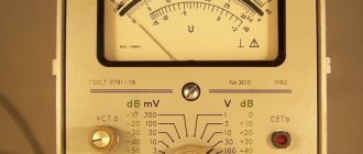
Voltmeter
Voltage drop is the quantity reflected in the change in potential in different parts of the conductor. The current flowing from the source towards the load changes its parameters due to the resistance of the wires, but its direction remains unchanged. You can measure the voltage using a voltmeter:
- two devices at the beginning and end of the line;
- alternate measurements in several places;
- a voltmeter connected in parallel to the cable.
The simplest circuit is a power source, conductor, load. An example would be an incandescent lamp plugged into a 220 V socket. If you measure the voltage on the lamp with a device, it will be slightly lower. The drop occurred in the lamp resistance.
The voltage or voltage drop across a section of a circuit can be calculated using Ohm's law using the formula U = IR, where:
- U – electrical voltage (volts);
- I – current strength in the conductor (ampere);
- R – resistance of the circuit or its elements (ohms).
Knowing any two quantities, you can calculate the third. In this case, it is necessary to take into account the type of current - alternating or direct. If there are several parallel connected resistances in the circuit, the calculation becomes somewhat more complicated.
Result of undervoltage
A common phenomenon is when the input voltage is detected below the established norm. Subsidence along the length of the cable occurs due to the passage of high current, which causes an increase in resistance. Losses also increase on long lines, which is typical for rural areas.
According to regulations, losses from the transformer to the most remote area should be no more than 9%. The result of deviation of parameters from the norm may be as follows:
- failure of energy-dependent installations and equipment, lighting devices;
- failure of electrical appliances at low input voltages;
- reduction in torque when starting an electric motor or compressor unit;
- starting current leads to overheating and shutdown of the engine;
- uneven current load at the beginning of the line and at the remote end;
- lighting fixtures operate at full intensity;
- losses of electricity, underutilization of current power.
The characteristics and operating parameters of electrical appliances are changing. For example, due to low power, the time for heating water by a boiler increases. A decrease in voltage leads to failures in the electronics.
In operating mode, voltage loss in the cable can be up to 5%. This value is acceptable for energy industry networks, since high power currents are delivered over long distances. Such lines are subject to increased requirements. Therefore, in case of household losses, attention should be paid to secondary energy distribution networks.
Causes of voltage drop
Phase imbalance in a three-phase circuit
First of all, you need to figure out whether it is the fault of the electricity supplier or the consumer. Network problems arise for the following reasons:
- deterioration of power lines;
- insufficient power of transformers;
- power imbalance or phase imbalance.
These problems are related to the supplier and cannot be resolved independently. To understand whether high-voltage lines are working correctly or not, you will have to call energy sales representatives. They will take measurements and draw up a conclusion.
You can make sure that the fault of the fall is not related to the supplier yourself. First of all, you should find out from your neighbors if they have similar problems. A multimeter is suitable for measuring voltage at home. Its cost is up to 1000 rubles. If the device at the entrance to the apartment shows normal voltage, the reason must be looked for in the home network.
The voltage may drop due to the long length of the wiring. When the length of the network exceeds 100 meters and the cross-section of the conductors is 16 mm, the oscillations will become regular. To correct the situation, you will have to change the wiring.
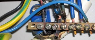
Weak contacts are additional resistance to current. It reaches devices in insufficient quantities. In addition, faulty contacts can cause a short circuit and lead to a fire. To normalize the performance, you need to replace the faulty section of the circuit and burnt contacts.
The culprit may be an incorrect connection of the wires running from the power lines to the house. Sometimes, contrary to safety requirements, copper wires are connected to aluminum or copper conductors are connected by twisting instead of terminals. The terminals and clamps are made of low-quality materials or their expiration date has expired.
Perhaps the fault lies in the input device itself. In this case, it should be replaced.
How to calculate losses
Linear relationship between voltage and current
When calculating an electrical line, voltage deviations should not exceed regulated standards. Permissible fluctuations for household single-phase networks are 209–231V; for a three-phase network, the voltage can vary from 361 to 399 V.
Fluctuations in current and power consumption lead to changes in voltage in the conductors near the consumer. Therefore, when drawing up a wiring diagram, it is necessary to take into account the allowable losses.
In a single-phase network there are two wires, so the voltage drop can be found using the following formula: U=I*R, in turn, R=(r*2i)/S.
- where r is the resistivity, which is equal to the resistance of a wire with a cross-section of 1 mm2 and a length of 1 m;
- i – designated as the length of the conductor;
- S – cable section.
AutoCad program for calculating voltage drop
In a three-phase network, the powers on the phase wires compensate each other, and the length of the neutral conductor is not taken into account, since no current flows through it. If the load across the phases is uneven, the calculation is performed as for a single-phase network. For long lines, capacitive and inductive reactance are additionally taken into account.
The fall can be calculated using an online calculator, and there are also special tables. They show the permissible current loads for different types of cables. When calculating the cable cross-section, the following data must be taken into account:
- conductor material;
- hidden or open laying of the line;
- current load;
- environmental conditions.
When current flows through a cable, wire or bus, it heats up. This process changes the physical properties of the conductors. The insulation melts, the contacts overheat, and the wire burns out. The reliability and uninterrupted operation of the electrical network depends on the correct selection of cable.
How to Reduce Voltage Drop and Cable Loss
You can reduce the amount of losses by reducing the resistance throughout the electrical network. Savings come from the method of re-grounding the zero on each power line support.
The cost of power supply with a long-distance line selected based on the permissible voltage drop is higher than the choice made based on cable heating. There is still an opportunity to reduce these costs.
- Strengthen the initial potential of the supply cable by connecting it to a separate transformer.
- You can achieve constant voltage levels in the network by installing a stabilizer near the load.
- Connection of consumers with low loads of 12–36 V is carried out through a transformer or power supply.
The longer the power line cable, the greater the resistance that occurs when current passes through it. Obviously, the voltage loss is also higher. They can be reduced by combining methods with each other.
- Reduce costs by increasing the cross-section of the power cable. But this method will require large financial investments.
- When developing power supply lines, you should choose the shortest possible path, since a straight line is always shorter than a broken line.
- As the temperature decreases, the resistance of metals decreases. Ventilated cable trays and other designs reduce line losses.
- Load reduction is possible if there are many power sources and consumers.
Savings come from proper maintenance and prevention of electrical networks - checking the density and strength of contacts, using reliable terminal blocks.
The issue of energy conservation must be approached with full responsibility. The problem of voltage loss can damage expensive devices and tools. Do not neglect safety measures; they will level out power surges and protect household appliances and equipment in the enterprise.
Loss Value Calculation
To ensure the operability of the equipment, it is necessary to make a calculation. It is carried out at the time of design. The current level of development of computer technology allows calculations to be made using an online calculator, which allows you to quickly calculate cable power losses.
To calculate, just enter the required data. Set the current parameters - direct or alternating. The power line material is aluminum or copper. Indicate by what parameters the power loss is calculated - by cross-section or diameter of the wire, load current or resistance.
Additionally, indicate the network voltage and cable temperature (depending on operating conditions and installation method). These values are inserted into the calculation table and calculated using an electronic calculator.
You can make a calculation based on mathematical formulas. In order to correctly understand and evaluate the processes occurring during the transmission of electrical energy, a vector form of representing characteristics is used.
And to minimize calculations, a three-phase network is represented as three single-phase networks. Network resistance is represented as a series connection of active and reactive resistance to the load resistance.
In this case, the formula for calculating power loss in a cable is significantly simplified. To obtain the necessary parameters, use the formula.
∆U= I*RL.
This formula shows the power loss of a cable as a function of the current and resistance distributed along the length of the cable.
However, this formula is valid if you know the current strength and resistance. Resistance can be calculated using the formula. For copper it will be equal to p=0.0175 Ohm*mm2/m, and for aluminum p=0.028 Ohm*mm2/m.
Knowing the value of resistivity, calculate the resistance, which will be determined by the formula
R=р*I/S, where р is resistivity, I is line length, S is cross-sectional area of the wire.
In order to calculate voltage losses along the cable length, you need to substitute the obtained values into the formula and perform calculations. These calculations can be made when installing electrical networks or security systems and video surveillance.
If power loss calculations are not made, this may lead to a decrease in the supply voltage to consumers. As a result, the cable will overheat, it may become very hot, and as a result, the insulation will be damaged.
Which may cause electric shock or short circuit to people. A decrease in line voltage can lead to failure of electronic equipment.
Therefore, when designing electrical wiring, it is important to calculate the voltage loss in the supply wires and laid cable
Calculation of voltage drop in a cable formula and reasons
Good afternoon, dear guests and readers of our blog! Today we would like to tell you about how to choose an electrical wire for the facility’s power supply system so that
I didn’t have to bite my elbows, complaining about power surges or lack of power to simultaneously power the entire complex of equipment.
The main emphasis in this matter is on the diameter of the wire for the current passing through it, and calculating the voltage drop in the cable is precisely intended to solve this problem.
Let's find out together how the calculation is made, and also find out how you can increase the power voltage of the electrical network, thereby increasing the safety of electrical installations.
What do we need to know?
Everyone knows that cable wiring transmits electricity from the source - power lines - to the final consumer - residential, administrative buildings, construction sites, etc.
When current flows through a metal wire, part of the energy is lost in it due to the resistance of the metal itself to the current.
Therefore, the consumer receives not the part of the electricity that left the source, but a slightly smaller one, taking into account losses during the movement of current.
To ensure optimal load distribution and voltage stability, the wire for the electrical network must be selected of a certain size - a cross-section that determines the diameter of the wire.
The voltage drop will also depend on the length of the conductor.
The calculated drop value should not deviate greatly from the original standard value.
As the connected load increases, the obstacles to the passage of current also increase.
In addition, with a small current, the resistance of the conductor increases, so the voltage drop occurs, because we all remember the mathematical relationship from school:
I = U/R.
Therefore, if you take two conductors of the same cross-section of different lengths, then the losses are higher for the longer one.
Consequently, when laying a current-carrying cable for power lines or other electrical installations, the main criterion, along with the cross-section of the conductor, is its length.
Is it possible to calculate this value in normal everyday conditions, using available means?
Of course, we can determine the voltage drop in three ways:
- Using two voltmeters, we measure this value at the ends of the cable.
- We measure the voltage sequentially on different sections of the wire. With this method, the readings may not be objective, because the load or network operating conditions may change.
- We connect one electrical device in parallel to the cable being measured. Errors are also possible here, because long connecting wires can affect the desired characteristic.
Important. The value of this value can be minimal - from 0.1 V. We recommend using instruments for measurements of at least accuracy class 0.2.
Result of voltage drop
What is the result of this process in a fundamental sense?
Let's see what happens when this characteristic of electrical energy decreases.
In accordance with the regulatory documentation of the PUE, losses during the movement of current from the transformer substation to the most remote area of the electrical load for a populated area should be no more than 9%.
In this case, losses of 4% are allowed from the main input to the electricity consumer, and 5% - from the transformer to the main input.
In three-phase communications, the standard value according to GOST 29322-2014 is 400 V ± 10% during normal operation of the line.
Deviation of this value from the standard can lead to the following results for stationary objects or electrical devices.
- Failures in the operation of electrical installations, improper operation of equipment, its failure, disruption of facility lighting.
- Disconnection of electrical appliances or failures of their correct operation.
- Reduced rotational acceleration of electric motors at start, energy loss, shutdown of devices when heated.
- Incorrect distribution of electrical load from the beginning of the line to the remote end of the wire between consumption objects.
- Work on 50% of room lighting devices.
The normal value for losses under standard operating conditions of a power line is 5%.
This value can be taken for electrical networks at the project stage.
Extended electrical mains are built for high-power currents.
Important. High demands are placed on the installation of power lines at all stages. Therefore, it is important to calculate losses in all sections of the highway, from the main main route to secondary lines.
Calculating the voltage drop
When calculating, be sure to take into account the active and reactive resistance, which make up the complex (total) resistance of the circuit, as well as power.
The formula for calculating this indicator on a section of a chain of length L looks like this:
∆U = (P * r0 + Q * x0) * L / Unom,
Where
- P—active power;
- Q - reactive power;
- r0—active resistance;
- x0 - reactance;
- Unom - rated voltage.
As we said above, in practice deviations from the standard indicator for the PUE are allowed. Permitted deviation limits:
- field lines – ±5%;
- indoor and outdoor household lighting – ±5%;
- industrial lighting (also for public buildings) – from +5% to -2.5%.
As a result of the calculation, we get a percentage indicator.
Let's give an example
The total power consumption of all appliances in the house is 2 kW.
All devices are connected to the network.
Then the current strength is I = 2 * 1000/220 = 9 A.
Next, we need to know the formula for calculating voltage losses.
It looks like this:
∆U = ( I * r * L ) / S.
Using this formula, we obtain the cable loss:
∆U = (I * R / U) * 100% = 2 (two wires) * 0.0175 / 1.5 * 30 = 0.7 Ohm.
Then the voltage drop value will be equal to:
∆U = (9 * 0.7 / 220) * 100% = 2.86%.
The resulting value fits within the normative indicator for the PUE of 5% deviation.
This value is also very beneficial for the end consumer, since he receives full power electricity with lower voltage electricity consumption.
This allows us to significantly reduce consumers' energy costs.
Another way to determine the amount of voltage loss involves using the table, which is presented in the specialized guidelines for power line engineers.
It takes into account all the technical qualities of the line and equipment, depending on which it is possible to “get” the loss value for certain operating conditions.
How to reduce voltage drop in the electrical network
When carrying out cable laying work, the cross-section of the wire taken according to the permissible reduction exceeds the value selected for heating the conductor.
This leads to higher prices for electricity for consumers.
How to reduce this figure?
After all, the final price for 1 kW of electricity depends on it.
Let's describe several ways to do this.
- Install a stabilizer near the load for network stability.
- Increase the potential value at the beginning of the cable by connecting to a separate transformer.
- Place a power supply or step-down transformer at a short distance from the consumer with a connected load of 12-36 V.
How to reduce cable losses
Voltage losses lead to additional costs.
In order to reduce this indicator, you can use the following methods.
- increase the cross-section of power cables;
- reduce the number of broken lines (turns) in the wiring, thereby reducing the length of the conductor route to reduce the overall resistance;
- lower the ambient temperature, because when a metal is heated, its resistance increases, cooling will have the opposite effect;
- reduce the load on the network;
- bring the angle between the voltage vector and the current vector to unity.
Comment. In order to reduce the resistance of the cable, and, accordingly, the loss of electricity in it, you can try to improve the ventilation in the cable structures and cable trays.
Dear readers, we have considered another issue regarding our security in relation to electricity supply, namely, we learned how to correctly calculate the voltage drop.
If the information was useful to you, recommend our blog to your friends, subscribe to us on social networks and always be protected!
All the best to you.
How to reduce losses?
One of the ways to reduce voltage loss in a conductor is to increase its cross-section. In addition, it is recommended to reduce its length and distance from the destination. In some cases, these methods cannot always be used for technical reasons. In most cases, reducing the resistance allows the operation of the line to normalize.
The main disadvantage of a large cable cross-sectional area is the significant material costs during use. That is why correct calculation and selection of the required diameter allows you to get rid of this trouble. The online calculator is used for projects with high-voltage lines. Here the program helps to correctly calculate the exact parameters for the electrical circuit.
Calculation of voltage drop: in a cable when powering loads with a loop
How to correctly and accurately calculate the cable cross-section based on voltage loss? Very often, when designing power supply networks, a competent calculation of cable losses is required. An accurate result is important for choosing a material with the required cross-sectional area of the core.
If the cable is chosen incorrectly, this will entail multiple material costs, because the system will quickly fail and cease to function.
Thanks to assistant sites, where there is a ready-made program for calculating the cable cross-section and losses on it, this can be done easily and quickly.
How to use an online calculator?
In the finished table you need to enter data according to the selected cable material, system load power, network voltage, cable temperature and method of laying it. Then click the “calculate” button and get the finished result. This calculation of voltage losses in a line can be safely used in work, if you do not take into account the resistance of the cable line under certain conditions:
- When specifying the power factor, cosine phi is equal to one.
- DC network lines.
- AC network with a frequency of 50 Hz made of conductors with cross-sections up to 25.0–95.0.
The results obtained must be used according to each individual case, taking into account all the errors of cable and wire products.
Be sure to fill in all values!
Why do you need to calculate the voltage loss in the cable?
Excessive energy dissipation in a cable can lead to significant power losses, excessive heating of the cable and damage to the insulation. This is dangerous for the lives of people and animals. With a significant length of the line, this will affect the cost of light, which will also adversely affect the financial condition of the owner of the premises.
In addition, uncontrolled voltage losses in the cable can cause the failure of many electrical appliances, as well as their complete destruction. Very often, residents use smaller cable sections than needed (in order to save money), which soon causes a short circuit.
And the future costs of replacing or repairing electrical wiring do not cover the wallets of “thrifty” users. That is why it is so important to choose the correct cross-section of cables for the wires being laid. Any electrical installation in a residential building should be started only after a thorough calculation of cable losses.
It is important to remember that electricity does not give a second chance, and therefore everything must be done correctly and efficiently from the beginning.
Ways to reduce power losses in cables
Losses can be reduced in several ways:
- increasing the cross-sectional area of the cable;
- decreasing the length of the material;
- load reduction.
Often the last two points are more difficult, and therefore you have to do this by increasing the cross-sectional area of the electric cable core. This will help reduce resistance.
This option has several costly aspects.
Firstly, the cost of using such material for multi-kilometer systems is very significant, and therefore it is necessary to choose a cable of the correct cross-section in order to reduce the threshold of power loss in the cable.
Online calculation of voltage losses allows you to do this in a few seconds, taking into account all additional characteristics. For those who want to double-check the result manually, there is a physical and mathematical formula for calculating voltage losses in a cable. Of course, these are excellent assistants for every electrical network designer.
Table for calculating wire cross-section by power
| Cable cross-section, mm2 | Open wiring | Gasket in channels | ||||||||||
| Copper | Aluminum | Copper | Aluminum | |||||||||
| Current | power, kWt | Current | power, kWt | Current | power, kWt | Current | power, kWt | |||||
| A | 220V | 380V | A | 220V | 380V | A | 220V | 380V | A | 220V | 380V | |
| 0,5 | 11 | 2,4 | – | – | – | – | – | – | – | – | – | |
| 0,75 | 15 | 3,3 | – | – | – | – | – | – | – | – | – | |
| 1,0 | 17 | 3,7 | 6,4 | – | – | 14 | 3,0 | 5,3 | – | – | – | |
| 1,5 | 23 | 5,0 | 8,7 | – | – | 15 | 3,3 | 5,7 | – | – | – | |
| 2,0 | 26 | 5,7 | 9,8 | 21 | 4,6 | 7,9 | 19 | 4,1 | 7,2 | 14,0 | 3,0 | 5,3 |
| 2,5 | 30 | 6,6 | 11,0 | 24 | 5,2 | 9,1 | 21 | 4,6 | 7,9 | 16,0 | 3,5 | 6,0 |
| 4,0 | 41 | 9,0 | 15,0 | 32 | 7,0 | 12,0 | 27 | 5,9 | 10,0 | 21,0 | 4,6 | 7,9 |
| 6,0 | 50 | 11,0 | 19,0 | 39 | 8,5 | 14,0 | 34 | 7,4 | 12,0 | 26,0 | 5,7 | 9,8 |
| 10,0 | 80 | 17,0 | 30,0 | 60 | 13,0 | 22,0 | 50 | 11,0 | 19,0 | 38,0 | 8,3 | 14,0 |
| 16,0 | 100 | 22,0 | 38,0 | 75 | 16,0 | 28,0 | 80 | 17,0 | 30,0 | 55,0 | 12,0 | 20,0 |
| 25,0 | 140 | 30,0 | 53,0 | 105 | 23,0 | 39,0 | 100 | 22,0 | 38,0 | 65,0 | 14,0 | 24,0 |
| 35,0 | 170 | 37,0 | 64,0 | 130 | 28,0 | 49,0 | 135 | 29,0 | 51,0 | 75,0 | 16,0 | 28,0 |
Calculation of voltage drop when feeding consumers with a loop
Calculating the voltage drop when powering consumers using radial circuits is quite simple. One section, one cable section, one length, one load current. We substitute this data into the formula and get the result.
When powering consumers via main circuits (loop), it is more difficult to calculate the voltage drop.
In fact, you have to perform several voltage drop calculations for one line: you need to perform a voltage drop calculation for each section.
Additional difficulties arise when the power consumption of electrical receivers powered by the main circuit changes. A change in the power of one electrical receiver is reflected in the entire chain.
How common is it in practice to supply power via main circuits and loops? There are many examples that can be given:
How to reduce losses?
One of the ways to reduce voltage loss in a conductor is to increase its cross-section. In addition, it is recommended to reduce its length and distance from the destination. In some cases, these methods cannot always be used for technical reasons. In most cases, reducing the resistance allows the operation of the line to normalize.
The main disadvantage of a large cable cross-sectional area is the significant material costs during use. That is why correct calculation and selection of the required diameter allows you to get rid of this trouble. The online calculator is used for projects with high-voltage lines. Here the program helps to correctly calculate the exact parameters for the electrical circuit.
Electricity losses in electrical networks: types, causes, calculation
Electricity losses in electrical networks are inevitable, so it is important that they do not exceed an economically justified level.
Exceeding technological consumption standards indicates problems that have arisen. To correct the situation, it is necessary to establish the causes of non-target costs and choose ways to reduce them.
The information collected in this article describes many aspects of this difficult task.
Types and structure of losses
Losses mean the difference between the electricity supplied to consumers and the energy actually received by them. To normalize losses and calculate their actual value, the following classification was adopted:
- Technological factor. It directly depends on characteristic physical processes, and can change under the influence of the load component, semi-fixed costs, as well as climatic conditions.
- Costs spent on operating auxiliary equipment and providing the necessary conditions for the work of technical personnel.
- Commercial component. This category includes errors in metering devices, as well as other factors causing under-metering of electricity.
Below is an average graph of losses for a typical electric company.
Approximate loss structure
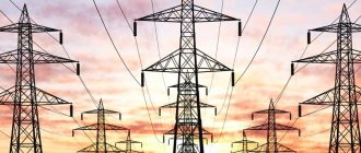
As can be seen from the graph, the highest costs are associated with transmission via overhead lines (power lines), this accounts for about 64% of the total losses. In second place is the corona effect (ionization of air near the overhead line wires and, as a consequence, the occurrence of discharge currents between them) – 17%.
Corona discharge on a power line insulator
Based on the presented graph, it can be stated that the largest percentage of non-targeted expenses falls on the technological factor.
Main causes of electricity losses
Having understood the structure, let's move on to the reasons that cause inappropriate expenditure in each of the categories listed above. Let's start with the components of the technological factor:
- Load losses occur in power lines, equipment and various elements of electrical networks. Such costs directly depend on the total load. This component includes:
- Losses in power lines are directly related to current strength. That is why, when transmitting electricity over long distances, the principle of increasing it several times is used, which contributes to a proportional reduction in current and, accordingly, costs.
- Consumption in transformers of a magnetic and electrical nature (1). As an example, below is a table that shows cost data for substation voltage transformers in 10 kV networks.
Losses in power transformers of substations
Non-target consumption in other elements is not included in this category due to the complexity of such calculations and the insignificant amount of costs. For this, the following component is provided.
- Category of semi-fixed expenses. It includes costs associated with the normal operation of electrical equipment, these include:
- Idle operation of power plants.
- Costs in equipment providing reactive load compensation.
- Other types of costs in various devices, the characteristics of which do not depend on the load. Examples include power insulation, metering devices in 0.38 kV networks, measuring current transformers, surge limiters, etc.
- Climatic component. Inappropriate consumption of electricity may be associated with climatic conditions characteristic of the area where power lines pass. In networks of 6 kV and higher, the magnitude of the leakage current in the insulators depends on this. In main lines from 110 kV, a large share of the costs falls on corona discharges, the occurrence of which is facilitated by air humidity. In addition, in the cold season, our climate is characterized by such a phenomenon as icing on the wires of high-voltage lines, as well as ordinary power lines. Ice on power lines
Taking into account the last factor, the energy costs for melting ice should be taken into account.
Costs for supporting the operation of substations
This category includes the cost of electrical energy for the operation of auxiliary devices. Such equipment is necessary for the normal operation of the main units responsible for the conversion of electricity and its distribution. Costs are recorded using metering devices. Here is a list of the main consumers belonging to this category:
- ventilation and cooling systems for transformer equipment;
- heating and ventilation of the technological room, as well as internal lighting fixtures;
- lighting of areas adjacent to substations;
- battery charging equipment;
- operational circuits and monitoring and control systems;
- outdoor equipment heating systems, such as air circuit breaker control modules;
- various types of compressor equipment;
- auxiliary mechanisms;
- equipment for repair work, communication equipment, as well as other devices.
Commercial component
These costs mean the balance between absolute (actual) and technical losses. Ideally, such a difference should tend to zero, but in practice this is not realistic.
This is primarily due to the characteristics of electricity meters and electricity meters installed at end consumers. It's about error.
There are a number of specific measures to reduce losses of this type.
https://www.youtube.com/watch?v=BSu1WKe6bEo
This component also includes errors in bills issued to consumers and theft of electricity. In the first case, a similar situation may arise for the following reasons:
- the contract for the supply of electricity contains incomplete or incorrect information about the consumer;
- incorrectly indicated tariff;
- lack of control over meter data;
- errors related to previously adjusted accounts, etc.
As for theft, this problem occurs in all countries. As a rule, such illegal actions are carried out by unscrupulous household consumers.
Note that sometimes incidents occur with enterprises, but such cases are quite rare, and therefore are not decisive.
It is typical that the peak of thefts occurs in the cold season, and in those regions where there are problems with heat supply.
There are three methods of theft (understating meter readings):
- Mechanical . This means appropriate intervention in the operation of the device. This can be slowing down the rotation of the disk by direct mechanical action, changing the position of the electric meter by tilting it by 45° (for the same purpose). Sometimes a more barbaric method is used, namely, the seals are broken and the mechanism is unbalanced. An experienced specialist will instantly detect mechanical interference.
- Electric . This can be an illegal connection to an overhead line by “throwing”, a method of investing a phase of the load current, as well as the use of special devices for its full or partial compensation. In addition, there are options with shunting the current circuit of the meter or switching phase and zero.
- Magnetic . With this method, a neodymium magnet is brought to the body of the induction meter.
The magnet can only affect some older models of electricity meters
Almost all modern metering devices cannot be “deceived” using the methods described above. Moreover, such attempts to interfere can be recorded by the device and stored in memory, which will lead to dire consequences.
The concept of loss standard
This term means the establishment of economically sound criteria for non-target expenditure for a certain period. When standardizing, all components are taken into account. Each of them is carefully analyzed separately.
As a result, calculations are made taking into account the actual (absolute) level of costs for the past period and an analysis of various opportunities that make it possible to realize the identified reserves to reduce losses.
That is, the standards are not static, but are regularly revised.
The absolute level of costs in this case means the balance between the transferred electricity and technical (relative) losses. Technological loss standards are determined by appropriate calculations.
Who pays for lost electricity?
It all depends on the defining criteria. If we are talking about technological factors and costs of supporting the operation of related equipment, then payment for losses is included in the tariffs for consumers.
The situation is completely different with the commercial component; if the established loss rate is exceeded, the entire economic load is considered an expense for the company that supplies electricity to consumers.
Ways to reduce losses in electrical networks
Costs can be reduced by optimizing the technical and commercial components. In the first case, the following measures should be taken:
- Optimization of the circuit and operating mode of the electrical network.
- Study of static stability and identification of powerful load nodes.
- Reduction of total power due to the reactive component. As a result, the share of active power will increase, which will have a positive impact on the fight against losses.
- Transformer load optimization.
- Equipment modernization.
- Various load balancing methods. For example, this can be done by introducing a multi-tariff payment system, in which the cost of kWh is increased during peak load hours. This will significantly reduce the consumption of electricity during certain periods of the day; as a result, the actual voltage will not “sag” below acceptable standards.
You can reduce your business costs by:
- regular search for unauthorized connections;
- creation or expansion of units exercising control;
- checking readings;
- automation of data collection and processing.
Methodology and example for calculating electricity losses
In practice, the following methods are used to determine losses:
- carrying out operational calculations;
- daily criterion;
- calculation of average loads;
- analysis of the greatest losses of transmitted power by day and hour;
- access to generalized data.
Full information on each of the methods presented above can be found in regulatory documents.
https://www.youtube.com/watch?v=BSu1WKe6bEou0026t=131s
In conclusion, we give an example of calculating costs in a TM 630-6-0.4 power transformer. The calculation formula and its description are given below; it is suitable for most types of similar devices.
Calculation of losses in a power transformer
To understand the process, you should familiarize yourself with the main characteristics of TM 630-6-0.4.
Parameters TM 630/6/0.4
Now let's move on to the calculation.
Calculation results
List of used literature
- Y. Zhelezko “Electricity losses. Reactive power. Power Quality: A Guide for Practical Calculations" 2009
- Pospelov G.E. “Power and energy losses in electrical networks” 1981
- Shvedov G.V., Sipacheva O.V.
, Savchenko O.V. “Losses of electricity during its transport through electrical networks: calculation, analysis, regulation and reduction” 2013 - Fursanov M.I.
“Definition and analysis of electricity losses in electrical networks of power systems” 2005
Normative references:
PUE 7th edition. Voltage levels and regulation, reactive power compensation.
1.2.22. For electrical networks, technical measures should be provided to ensure the quality of electrical energy in accordance with the requirements of GOST 13109.
1.2.23. Voltage regulation devices must ensure that the voltage on buses with a voltage of 3-20 kV of power plants and substations to which distribution networks are connected is maintained within a range of not less than 105% of the rated value during the period of highest loads and not higher than 100% of the rated value during the period of least load of these networks. Deviations from the specified voltage levels must be justified.
1.2.24. The selection and placement of reactive power compensation devices in electrical networks are made based on the need to ensure the required network capacity in normal and post-emergency modes while maintaining the required voltage levels and stability margins.
Voltage deviation is characterized by an indicator of steady-state voltage deviation, for which the following standards are established:
- Normally permissible and maximum permissible values of the steady-state voltage deviation δUу at the terminals of electrical energy receivers are equal to ± 5 and ± 10%, respectively, of the rated voltage of the electrical network according to GOST 721 and GOST 21128 (rated voltage);
- Normally permissible and maximum permissible values of steady-state voltage deviation at points of common connection of electrical energy consumers to electrical networks with a voltage of 0.38 kV or more must be established in contracts for the use of electrical energy between the energy supply organization and the consumer, taking into account the need to comply with the norms of this standard at the terminals of the receivers electrical energy.
RD 34.20.185-94 Instructions for the design of urban electrical networks. Ch. 5.2 Voltage levels and regulation, reactive power compensation
5.2.4. Preliminary selection of wire and cable sections can be made based on the average values of the maximum voltage losses in normal mode: in 10(6) kV networks no more than 6%, in 0.38 kV networks (from transformer substations to building inputs) no more than 4-6 %.
Larger values refer to lines supplying buildings with less voltage loss in intra-house networks (low-rise and single-section buildings), smaller values - to lines supplying buildings with greater voltage loss in intra-house networks (multi-storey multi-section residential buildings, large public buildings and institutions).
SP 31-110-2003 Design and installation of electrical installations of residential and public buildings. 7. Electrical network diagrams.
7.23 Voltage deviations from the nominal voltage at the terminals of power electrical receivers and the most remote electric lighting lamps should not exceed ±5% in normal mode, and the maximum permissible in post-emergency mode at the highest design loads is ±10%. In networks with a voltage of 12-50 V (counting from a power source, for example a step-down transformer), voltage deviations are allowed to be accepted up to 10%.
For a number of electrical receivers (control devices, electric motors), a voltage reduction in starting modes is allowed within the limits of the values regulated for these electrical receivers, but not more than 15%.
Taking into account the regulated deviations from the nominal value, the total voltage losses from the 0.4 kV busbars of the transformer substation to the most distant general lighting lamp in residential and public buildings should, as a rule, not exceed 7.5%. The range of voltage changes at the terminals of electrical receivers when starting an electric motor should not exceed the values established by GOST 13109.
GOST R 50571.15-97 (IEC 364-5-52-93). Electrical installations of buildings. Part 5. Selection and installation of electrical equipment. Chapter 52. Electrical wiring. 525. Voltage losses in electrical installations of buildings.
IEC 60364-7-714-1996, IEC 60364-7-714 (1996). Electrical installations of buildings. Part 7. Requirements for special installations or premises. Section 714. Exterior lighting installations.
in a free translation by the author of the article:
714.512. The voltage drop under normal operating conditions must be compatible with the conditions resulting from the inrush current of the lamps.