Dynamic (electrodynamic) braking
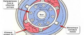
If you disconnect the motor from the AC power supply and connect it to a DC source, dynamic braking will occur. The stator winding, when direct current flows, will create a stationary magnetic field. When rotating in such a field, an EMF will be induced in the rotor, under the influence of which a current will flow. This current will interact with the stationary field of the stator and create a braking torque, which will be directed against the direction of rotation of the rotor. As a result, the engine will gradually stop, and the speed of its stopping will depend on the strength of the direct current flowing through the stator, and, of course, on the stored kinetic energy of the electric drive. This energy, converted into electrical energy, is dissipated in the form of heat on the rotor.
In a motor with a wound rotor, the magnitude of the braking torque, and therefore the braking speed, can be changed by changing the value of additional resistances in the rotor circuit.
Regenerative (generative) braking
Regenerative braking is used mainly as a brake before the main braking, or when lowering loads, for example in elevators.
For regenerative braking to occur, the rotor speed must exceed the synchronous speed. In this case, the engine will begin to supply energy to the network, that is, it will become an asynchronous generator. In this case, the electromagnetic torque of the motor becomes negative and has a braking effect.
Generator braking can be achieved in several ways. For example, in two-speed engines, when switching from a higher speed to a lower one. In this case, the rotor rotates by inertia at a frequency higher than the new synchronous frequency. A braking torque will occur, which will reduce the speed to the new nominal speed.
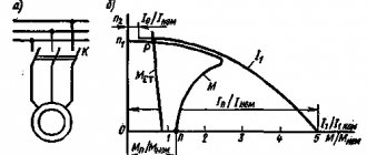
Let us assume that at the initial moment of time our engine was operating at characteristic 1 at point A, after switching the speed to a lower one, it switched to characteristic 2 at point B, and then, under the influence of the braking torque, reached point C, at a lower speed.
Generator braking can be achieved by reducing the frequency of the motor supply. This is possible if the motor is powered by a thyristor frequency converter. As the voltage frequency decreases, the synchronous rotation speed decreases. The rotation speed of the rotor, which rotates by inertia, will again be higher, and a braking torque will arise, which will reduce the rotor speed. In this way, the engine can be brought to a complete stop.
Switching to generator mode
This method is only feasible if the motor rotor rotates at a speed greater than the stator magnetic field. This is possible when the number of pole pairs changes to more than it was before braking. It is worth noting that as soon as the rotor speed drops below synchronous speed, the machine will automatically switch to motor mode. Also not unimportant is the fact that with this method it is impossible to completely stop the rotation of the engine rotor, but only to slow it down to a certain value.
With this braking mode, the asynchronous machine does not consume electrical energy from the network, but rather produces and supplies it to the network. When switching an asynchronous motor to generator mode for braking purposes, you can disconnect the stator windings of the asynchronous machine and connect a resistor to them, and the higher the resistance of the resistor, the greater the braking torque.
Back braking
Back braking is used to quickly stop the engine. This can be done in several ways. In the first method, with the engine running, two phases are swapped by turning off contactor K1 and turning on K2. In this case, the direction of rotation of the stator magnetic field changes to the opposite. A large braking torque occurs and the engine stops quickly. But in order to limit large currents at the moment of increasing braking torque, it is necessary to introduce additional resistance into the stator or rotor winding.
In the second method, the engine is used as a brake for the load. That is, if the load goes down, then the engine should work, on the contrary, to rise. To do this, a large additional resistance is introduced into the motor rotor circuit. But its starting torque turns out to be less than the load torque, and the engine operates at a certain low speed, thereby ensuring a smooth descent.
In essence, counter-switch braking is carried out according to the engine reverse circuit.
Electric machines are characterized by two main operating modes: motor and braking. During braking operation, the mechanical energy supplied to the machine is converted into electrical energy. The resulting torque does not coincide with the direction of rotation of the machine and it slows down. Although there are several different methods of electric braking, however, with all methods, fundamentally the same process occurs. The methods themselves differ from each other only in their connection diagram and characteristics. The electrical energy generated during braking is used in different ways for different methods. In some cases, it is transmitted to the electrical network and usefully used there, in others it is converted into heat in additional resistances and an armature.The need to use electric braking methods in electric drives of lifting mechanisms is caused by the specifics of their operation. Braking makes it possible to facilitate the work of mechanical brakes, obtain stable constant speeds for lowering loads, and also ensures accelerated stopping of drives.
For electric motors with parallel excitation, three braking modes can be used:
a) generator with energy output to the network;
b) electrodynamic;
c) backflow (counterflow).
Generator mode with energy output to the network. As indicated, when the electric motor operates on a natural or artificial characteristic in the motor mode, the counter-emission induced in the armature winding. d.s. always less than the applied voltage (E
This current creates a torque of the electric motor M = kФIа, coinciding with the direction of rotation of the armature. At idle speed of the electric motor, when there is no moment of resistance on the shaft, the current in the armature winding should be equal to zero, i.e. in this case, counter current. d.s. equal to the applied voltage:
Thus, when the electric motor speed changes from 0 to n0, the opposite e.g. d.s. induced in the armature winding is always less than the applied voltage (or, in extreme cases, equal to it) and the current in the armature winding, according to expression (22), is positive, which is typical for the motor operating mode of the machine.
If, under the influence of an external moment, for example, the moment created by the weight of a lifted load, the number of revolutions of the electric motor becomes greater than n0, it will counteract. d.s. exceeds the applied voltage and current in the armature winding, according to expression (22), it will change direction, i.e. the machine will turn from a consumer of electrical energy into its source. Obviously, when the direction of the current changes, the direction of the torque created by the electric motor also changes. This torque becomes braking and balances the external torque applied to the motor shaft. This means that in the equations of speed and mechanical characteristics the minus sign changes to plus
that is, the characteristics of the generator mode are a continuation of the characteristics of the motor mode of the machine and are located in the II or IV quadrants (Fig. 16). It is easy to notice that when additional resistances are introduced into the armature circuit, the speed of the electric motor in generator mode does not decrease, but, on the contrary, increases.
This method of electric braking is very economically beneficial, since it allows you to return to the network a significant part of the electricity spent, for example, on lifting a load. However, it is only feasible at elevated speeds, much higher than the rated speed of the electric motor, and is therefore not always applicable. Braking with energy release into the network cannot be used to stop the drive, since pbr must always be greater than n0. Experienced crane operators most often use this method of braking when loading ships, when the height of the lifting load is significantly less than the height of the lowering. In this case, carrying out the lowering of the load in generator mode with the release of energy into the network, it is possible to obtain significant energy savings and thereby improve economic indicators.
Electrodynamic braking mode . Despite the significant economic effect, braking with energy release into the network is used relatively rarely, which is explained by the above-mentioned disadvantages of this method of braking. The so-called electrodynamic braking is more often used, which can be used both to limit the speed of lowering loads and to speed up the stop of the drive.
The dynamic braking mode is understood as the mode that occurs when the rotating armature is disconnected from the network and closed to a resistance called the dynamic braking resistance Rd. diagram shown in Fig. 17, this is done by opening contacts L, which were closed in motor mode, and closing contact T. In this case, the equations for speed and mechanical characteristics will take the form:
These equations can be obtained from expressions (27) and (32), putting U = 0 in them and replacing R with Rd. Equations (46) and (47) show that the characteristics of parallel-excitation electric motors in dynamic braking mode are linear and pass through the origin (see Fig. 17). It is obvious that higher resistances Rd correspond to softer characteristics, and at the same speed - lower braking torques and currents.
Let us consider the features of the dynamic mode using the example of an electric drive of a lifting mechanism. When lifting a load, contacts L should be closed and contact T should be open. Let’s say that an electric motor, lifting a load, operates stably at point 1 on the natural characteristic a (M = Ms) at a speed +n1. When contacts L open and contact T closes, the electric motor must switch to an artificial characteristic b passing through the origin of coordinates.
The electric motor has a certain inertia, therefore, without changing the rotation speed, it moves from point 1 to point 2 or 2′ on characteristic c, depending on the resistance value Rd. At the same time, the direction of the torque changes and the electric motor begins to brake intensively. When the speed decreases to zero, contact T must be opened and the mechanical brake must be applied. If contact T is not open, then under the influence of the load the electric motor will begin to rotate in the opposite direction, lowering the load in dynamic braking mode.
Stable operation of the electric motor will be at point 3 or 5, since when operating at these points M = Ms. Thus, the dynamic braking mode can be used not only to stop, but also to obtain a certain steady speed. In the case under consideration, when lowering the load, the torque developed by the electric motor is the same in magnitude and sign as when lifting. However, the direction of speed when passing through point O has changed, so the torque developed by the electric motor when lowering the load will be a braking torque, limiting the speed of descent. The load will fall at a steady speed - n3 or n2.
This method of braking is simple and does not require complex switching in the circuit; it allows you to regulate the braking time or the speed of lowering the load by adjusting the resistance value Rd. To implement braking using this method, almost no energy consumption is required, since in practice the braking process consists in the fact that the machine operates as a generator with independent excitation, closed to a resistance Rd. Mechanical energy from the mechanism being braked is transferred to the shaft of the electric machine. In the machine it is converted into electrical energy, and the latter into thermal energy in the windings of the machine and in the resistance Rd.
The main disadvantage of the method under consideration is the rather significant braking time, since at low speeds the braking torque values are very small and this method cannot be considered appropriate when it is necessary to quickly stop the electric drive.
Anti-switching mode . To carry out braking of electric drives of hoisting and transport machines, the counter-switching mode is often used, which is understood as a mode when the electric motor, being connected to the network, rotates in the direction opposite to that in which it would rotate if it were turned on in the same way in the motor mode. This method of braking can be used to limit the speed of lowering loads and speed up the stop of the drive.
Let's say the electric motor is turned on according to the circuit shown in Fig. 18, a and, lifting the load, works on the natural characteristic a at point 1 (Fig. 18, b) at M = Mc (contacts 1B, 2B and P are closed). When contact P opens in the electric motor circuit, the additional resistance Rt will be switched on and the electric motor will switch to artificial characteristic b at point 2 (see Fig. 18, b). Since the torque developed at point 2 will be less than the moment of resistance forces (M<Mc), the speed of the electric motor will begin to decrease rapidly and at point 3 will become equal to 0. If you need to stop the electric motor, then at speed n = 0 it should be disconnected from the network . If the electric motor is not disconnected from the network, then under the action of the load it will begin to accelerate in the opposite direction. As the electric motor accelerates, the braking torque on its shaft increases and at a speed of n2 (point 4) it will become equal to the torque created by the weight of the lifted load. The operation of the electric motor at point 4 on characteristic b will be stable and the speed of lowering the load will be limited by the value -n2. The speed of descent in this case can be adjusted by changing the value of additional resistance Rt introduced into the armature circuit. The higher the value of this resistance, the softer the characteristic b and the higher the speed of descent of the load.
In the case under consideration, when the electric motor switches to the counter-start mode, the speed changes its sign, but the sign of the torque (and current) remains unchanged compared to the motor mode. This is what causes the braking effect. The machine turns into a source of electricity, which is consumed in the armature circuit resistances. In these same resistances, as well as in the excitation winding, the electricity that comes from the network is consumed.
In cases where the direction of the moment of resistance on the electric motor shaft is determined by the direction of its rotation, the counter-switching mode cannot be obtained using the above method. In this case, to speed up the stop or quickly reverse the drive, it is necessary to switch the armature winding.
Let's assume that in the diagram in Fig. 18, and contacts 1B, 2B and P are closed and the electric motor operates stably on the natural characteristic a at point 1 (Fig. 18, c) at M=Mc. To perform fast braking or reverse, you need to open contacts 1B and 2B and close contacts 1H and 2H. In this case, the direction of the current, and therefore the torque, changes and the electric motor will be in the back-to-back braking mode. To avoid a large surge of current and torque, it is necessary to open contacts P simultaneously with contacts 1B and 2B, which leads to the introduction of additional resistance. Then, when contacts 1H and 2H are closed, the electric motor switches to characteristic b, passing through the point - n0. Initially, the electric motor will switch to operation corresponding to point 2 on characteristic b. Since the torque of the electric motor and the static torque do not correspond to the direction of the speed, the latter begins to rapidly decrease and at point 3 will become equal to zero.
If you need to stop the electric motor, then at speed n = 0 it should be disconnected from the network; if it is necessary to reverse, then at n = 0 the resistance Rt is turned off, after which the normal start of the electric motor begins in the opposite direction.
Counter-inhibition braking is quite effective for horizontal movement mechanisms of bridges and crane trolleys and slewing mechanisms. It is also used to brake lifting mechanisms, especially when lowering heavy loads. However, from an economic point of view, the back-off mode is not profitable, since not only the braking energy, but also the energy supplied from the network is converted into heat in the machine windings and additional resistance. The additional resistance Rt should be approximately equal to the total resistance of the starting rheostat. This is due to the fact that in the anti-switching mode e. d.s. The armature winding coincides in direction with the applied voltage and significant resistance is required to limit the currents arising in this mode. This means that in order to reduce the current that occurs when the electric motor is switched to the back-on mode to acceptable values, it is necessary to include not only an additional resistance Rt in the armature circuit of the electric motor, but also a starting rheostat. In this case, the tone in the armature winding, according to expression (22), will be
where R is the resistance of the starting rheostat.
Changing the direction of rotation . Changing the direction of rotation (reverse) of an electric motor with parallel excitation can be done in two ways: changing the direction of the current in the field winding or changing the direction of the current in the armature winding. In both cases, the direction of the torque changes, according to expression (5), which causes the reversal of the electric motor. In practice, the second method is usually used, which provides a faster change in the direction of rotation. This is explained as follows:
a) opening the excitation circuit requires preliminary opening of the armature circuit, which is associated with the complication of the equipment. Opening the armature is necessary to prevent an excessive increase in the current in it when the magnetic flux decreases;
b) the excitation winding of a parallel excitation electric motor has significant inductance and its rupture is associated with the danger of insulation breakdown;
c) when the direction of the current in the excitation winding changes, the machine is remagnetized, which increases the duration of the operation and leads to additional energy losses, especially with frequent reverses.
In practice, to reverse an electric motor with parallel excitation, contacts 1B, 2B, 1H and 2H are used in this manner (see Fig. 18, a). When the electric motor is running, either contacts 1B and 2B, or 1H and 2H are closed in pairs. Switching them leads, as can be seen from the diagram, to a change in the direction of the current in the armature winding, and the latter to a change in the direction of rotation of the electric motor.