Asynchronous electric motors are complete systems, the quality of which is determined by technical characteristics. We will describe below why they are needed and how they are measured and changed. Engine parameters are the first thing you need to know before starting to operate it.
Asynchronous motor
In order to ensure the normal, coordinated operation of asynchronous power units, it is necessary to know everything about these motors, in particular, their operating and mechanical characteristics. This is necessary both when purchasing components in a store and when selling them yourself. Also, by properly regulating these indicators, you can successfully control the operation of the engine, ensuring not only high productivity, but also reduced energy costs.
Common parameters
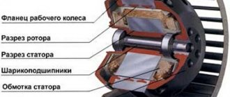
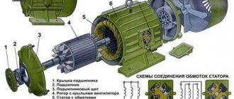
By default, a standard asynchronous type machine (without modifications or modifications) includes 2 main components:
- stator – a stationary part;
- rotor is a part that can be rotated.
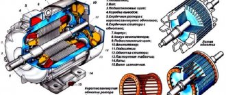
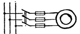
In three-phase models, the 3 separate phases represent the stator winding. C1, C2, C3 in the figure are their beginnings, and C3, C4, C5 are their ends. Absolutely all of them are connected to terminal connectors using one of two circuits: “star” or “delta”. In the image they can be seen under options B and C.
Asynchronous motor device diagram
The specific circuit for construction is selected taking into account the passport data of the electric motor and the mains voltage from which the power will be supplied.
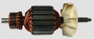
The main task of the stator is to create a magnetic field inside the motor, which rotates uninterruptedly. There are two types of rotor - phase and short-circuited. The latter has a speed that cannot be controlled. The use of such a component in a power unit makes the design simpler and cheaper. The starting moment of such devices, however, is low, which cannot be said about motors with a wound rotor. Its rotation speed is controlled by introducing an auxiliary resistance.
Tags
stator windings mains stator. in the stator is laid on the stator. the stator flux is one per stator. stator slots divide the stator poles increase on the stator four for example the stator has if the rotor is an auxiliary rotor. the name of the rotor. the quality of the rotor can the shaft of the rotor part. rotation of the rotor rotations of the rotor which indicator of the rotor. with direct current alternating current direct current Generated current and movement of currents movement of currents in movement of current variations of current in electric current in
division
Motor operating principle
The first thing that happens is that electrical voltage is applied to the stator winding. For each individual phase, you can see constantly changing magnetic fluxes, shifted relative to each other by an angle of 120 degrees. The result is a total resultant flux, which is also rotating, and with its help, an electromotive force is created inside the rotor conductors.
This is how the result is a current that is combined with the resulting flow, which creates the starting moment. And he, in turn, sets the rotor in motion.
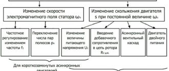
This is a general, simplified description of the principle of operation of a power unit at different speeds. In order to consider the operation of the motor, it is worth delving into the mechanical and performance characteristics that precisely influence the operation algorithm described above.
Components of an electric machine
The basis for an electric machine is the rule of electrical induction with magnetic induction. Such a device includes a stator or, as it is called, a constant part (typical for asynchronous, synchronous machines of variable current) or an inductor (for devices of constant current) and a rotor, it is called an active or moving part (for asynchronous and synchronous machines of variable current) or an armature (constant current devices). Magnets (of a constant state) are actively used as a constant part for current machines with low power.
Mechanical characteristics
The essence of this parameter is the direct dependence of the rotor speed on the load indicators. That is, from the moment of rotation on the shaft. When the load is at the nominal level, the rotation speed for different types of motors varies in the range from 92.5 to 98% of the speed n1. Slip (Snom) does not exceed a level of 2 – 7.5%.
Mechanical characteristics
The higher the load level with which the motor operates, the lower the speed of the electric motor. The speed of an asynchronous motor decreases insignificantly as the load increases, ranging from zero to the maximum value. Visually, this can be seen above, in Figure A. It follows from this that the electric unit belongs to motors with a rigid mechanical characteristic.
M max., that is, the greatest torque, the unit develops when there is a certain slip (Skp), which is at a level of 10 to 20 percent. The ratio of the values Mmax and Mnom indicates the overload capacity of the motor. The ratio of Mn to nominal M indicates the starting qualities of the electric motor.
An electric motor is capable of stable and uninterrupted operation provided that self-regulation is ensured, when a balance is automatically established between the load torque aimed at the shaft (Mvn) and the M torque, which is developed directly by the engine. This condition is perfectly displayed at the top of the characteristic, when the maximum indicator M is reached. In other words, to the level of point B.
In situations where the load torque M exceeds Mmax, the motor has reduced stability and stops. In parallel with this, a current several times higher than the rated current will be supplied to the machine windings for quite a long time, which can lead to burnout. The temperature of the parts increases due to excess electricity.
When connecting the rotor windings from the starting rheostat to the electrical circuit, we get a full set of mechanical characteristics at the output. The first parameter when operating a motor without a starting rheostat is called the natural characteristic. The second, third and fourth indicators, which are obtained when connecting a rheostat to the rotor winding of the motor, have resistances R1p (2p and 3p, respectively), and relate to the mechanical characteristics of the rheostat type.
When the starting rheostat is started, the mechanical characteristic is called soft or steeply falling. This is due to the fact that the active resistance index of the rotor chain R2 increases significantly and Scr increases. At the same time, the starting current is reduced. This value (Mp) is also regulated by R2. At the same time, it is possible to select a rheostat with a certain resistance so that the starting moment (Mn) is equal to the maximum M.
Electromechanical characteristics
The indicator is the dependence of the angular speed of revolutions on the stator current. By using several control points at once, you can create such a characteristic. To do this, calculate the following values:
- rated current:
Example calculation
- critical slip:
Calculation
- current level at the initial moments of start.
Initial starting moment
All these values reflect the electromechanical characteristic as accurately as possible.
Rotation speed measurement
Measuring the speed of rotation of shafts, gears, wheels and other elements is usually carried out using electronic tachometers. A typical diagram of an electronic tachometer is shown in Fig. 26.
Tachometers measure rotation speed n with dimension . Already the first glance at this dimension makes it clear that the tachometer must perform two types of measurements simultaneously. First, measure the number of revolutions (shaft, gear, wheel, etc.). Secondly, measure time. To perform such measurements, the electronic tachometer (Fig. 26) contains an electronic stopwatch, a photoelectric sensor and a LU logic device.
We got acquainted with the structure and operation of an electronic stopwatch in the previous section. Now let's get acquainted with the device and operation of the photoelectric sensor. It consists of a LED - an LED emitter, a photodiode - an FD receiver and an electrical pulse shaper FS1. The LED emits light onto the photosensitive surface of the photodiode of the PD receiver. In this case, the resistance of the photodiode drops. If an opaque material is placed on the light line between the LED and the PD photodiode, the resistance of the PD photodiode will increase sharply.
Rice. 26. Functional diagram of an electronic tachometer
This property of a photoelectric sensor is widely used in engineering and measurement. To measure the rotation speed, a disk 1 with holes rotating on shaft 2 is placed between the optocoupler (LED emitter and photodiode receiver) (Fig. 26). As the shaft rotates, 2 holes in the disk will interrupt the light flow between the LED LED and the PD photodiode. In this case, the resistance of the PD photodiode will continuously change synchronously with the shaft rotation frequency. The FS1 pulse shaper responds to changes in the resistance of the photodiode, converting each of them into rectangular electrical pulses at its output, standard in voltage and duration (see Fig. 27, (a). The faster disk 2 rotates, the higher the pulse repetition rate at the output of the shaper FS1.
Now let's get acquainted with the operation of the logical device of the LU (Fig. 26). A logic device has two inputs and one output. The principle of its operation can be formulated as “2-I”. That is, if voltage is applied to both the first and second inputs of the logical device LU (the “2-I” condition is met), then there will also be voltage at its output. If there is no voltage at at least one of the inputs of the LU (condition two “AND” is not met), then there will be no voltage at its output. This principle of LU operation is well illustrated by the graphs presented in Fig. 27.
Rice. 27. Graphs of electrical pulses during operation of the electronic tachometer circuit, (A) – pulses at the output of the FS1 driver at point A; (B) – pulses of counting time periods (from the output of the dividing decade DD4); (B) – pulses at the output of the logical device (at the input to SchD1); (D) – pulses that reset the counting decades at the start of a new counting period
In the process of measuring the rotation speed of shaft 2 with a tachometer (Fig. 26), electrical pulses are generated at the output of the FS1 driver at point (A) with the repetition rate of the holes in disk 1. These pulses are supplied to the first input of the logical device LU. At the same time, pulses of counting time periods arrive at the second input of the LU at point (B) from the output of the dividing decade DD4.
Looking at Fig. 27. It is not difficult to see that the “2-I” condition can be periodically fulfilled only at the moment when a voltage of 5 volts is applied to the second input of the LU at point (B) for 1 second. At the same time, electrical pulses caused by the rotation of disk 2 arrive from the output of the FS1 driver to the first input of the LU at point (A). Thus, at the output of the logical device of the LU at point (B), rectangular electrical pulses are formed, which in appearance repeat the pulses coming from the FS1 driver. They arrive at the counting decades of the SChD, which is why this mode is called “counting”.
After the pulse counting period, during the next period of time lasting 1 second, the voltage at the second input of the LU becomes zero. At the output of the LU, the voltage also becomes zero, since the “2-I” principle is not fulfilled. Accounting is not possible. On the counting decades, the counting result is displayed for one second. This mode is called "indication".
After the “indication” mode, the automatic control device for resetting the UUS (Fig. 26) generates at its output at point (D) a short electrical pulse, which is supplied simultaneously to the zeroing inputs of all counting decades. The counting decades are reset to zero and a new counting mode begins. Thus, the “counting” and “indication” modes are repeated cyclically.
To determine the rotation speed of a shaft, gear, etc. from the readings of an electronic tachometer, use the formula:
(2.18)
where: N – counting result on the counting decade displays; k – number of holes in the sensor disk; t – counting time period.
For example, the number 2400 was displayed on the counting decade displays of the electronic tachometer. There are 80 holes in the sensor disk. The counting time period is 1 second. In this case:
rps
If 60 holes are made in the circumference of the disk, and the counting period is equal to 1 second, then, taking into account the fact that there are 60 seconds in 1 minute, the electronic tachometer will show the rotation speed in the dimension .
The absolute error Δn of measuring the speed of an electronic tachometer is calculated using the following formula:
, (2.19)
where: Δtmeas – absolute error in the duration of the time pulse (from the instability of the reference frequency generator); nх – measured rotation speed; tmeas – duration of the time pulse (in our example it is equal to 1 second).
The relative error in measuring the speed with an electronic tachometer is determined by the formula:
(2.20)
For example, it is necessary to determine the absolute and relative errors in measuring the number of revolutions with an electronic tachometer if it shows the value of the measured rotation speed nx = 1000 rpm, and the absolute error in the duration of the time pulse Δtmeas = 0.0001 s. Using formula (2.19), we determine the absolute error in measuring the speed with an electronic tachometer:
Performance characteristics
These parameters indicate the dependence on the useful power P2 = P max. such indicators:
- rotation (n) or slip (S) frequencies;
- gross moment (M2);
- stator current I1;
- Efficiency (coefficient of efficiency).
Performance characteristics
In this case, the values of frequency f1 and voltage U1 must be at nominal levels. They are implemented for areas of stable motor operation. This means that the range should be from zero slip to one that exceeds the nominal by 10 - 20%.
The speed of revolutions with increasing power output is difficult to change. This could already be seen in the mechanical characteristics, when the gross torque M2 is proportional to the power indicator P2. The torque is lower than the electromagnetic torque, the difference is the value of the braking torque Mtr, which is generated by friction forces.
The stator current I1 increases with the power output, but when P2 is zero, there is a certain current for idling - I0. The efficiency level also decreases, almost identically to that of a transformer, while maintaining a fairly high value over a relatively wide range of loads.
The highest efficiency for asynchronous power units with medium and high power varies between 0.75 - 0.95. The higher the power of the machine, the greater its efficiency.
The power coefficient cosine ϕ1 for asynchronous motors of similar characteristics with a maximum load is 0.7 - 0.9.
Based on this, it can be seen that power units overload electrical substations and power networks with their rather impressive currents, which can reach from 40 to 70% of the rated currents. This is one of the most significant disadvantages of installations of this type.
If the motor loads are an order of magnitude smaller, for example 25 - 50% of the workers, then the power coefficient drops to insufficient values - 0.5 - 0.75. When the load is removed from the motor, the power factor decreases further and the new indicators are 0.25 - 0.3. That is why it is impossible to allow an asynchronous motor to operate for a long time at idle speed, as well as at significant underloads.
Asynchronous motor control
- Methods for connecting an asynchronous electric motor to the power supply:
- direct connection to power supply
- connection from soft starter
- connection from frequency converter
Options for connecting an asynchronous electric motor using a magnetic starter (left), a soft starter (in the middle) and a frequency converter (right). The diagrams are presented in a simplified form. FU1-FU9 - fuses, KK1 - thermal relay, KM1 - magnetic starter, L1-L3 - contacts for connecting to a three-phase alternating current network, M1-M3 - asynchronous electric motors, QF1-QF3 - circuit breakers, UZ1 - soft starter, UZ2 - frequency converter
Direct connection to mains power
The use of magnetic starters allows you to control asynchronous electric motors by directly connecting the motor to an alternating current network.
Using magnetic starters you can implement the following circuit:
- non-reversible start: start and stop;
- reverse start: start, stop and reverse.
The use of a thermal relay makes it possible to protect the electric motor from current values much higher than the rated value.
Non-reversible circuit
Reversible circuit
The disadvantage of direct commutation of the windings of an asynchronous electric motor with the network is the presence of large starting currents when starting the electric motor.
Smooth start of an asynchronous electric motor
In tasks where it is not necessary to adjust the speed of the electric motor during operation, a soft starter is used to reduce starting currents.
The soft starter protects the asynchronous electric motor from damage caused by a sharp increase in energy consumption during starting by limiting the starting currents. The soft start device allows for smooth acceleration and braking of an asynchronous electric motor.
A soft starter is cheaper and more compact than a frequency converter. Used where adjustment of rotation speed and torque is required only during startup.
Frequency control of an asynchronous electric motor
To regulate the rotation speed and torque of an asynchronous motor, a frequency converter is used. The operating principle of a frequency converter is based on changing the frequency and voltage of alternating current.
- Using a frequency converter allows you to:
- reduce the energy consumption of the electric motor;
- control the rotation speed of the electric motor (soft start and stop, speed adjustment during operation);
- avoid overloading the electric motor and thereby increase its service life.
Functional diagram of variable frequency drive
- Depending on the functionality, frequency converters implement the following control methods with an asynchronous electric motor:
- scalar control;
- vector control.
Scalar control
is simple and cheap to implement, but has the following disadvantages - slow response to load changes and a small control range. Therefore, scalar control is usually used in tasks where the load is either constant or varies according to a known law (for example, fan control).
Scalar control of an asynchronous motor with a speed sensor
Vector control
used in tasks where it is necessary to independently control the speed and torque of an electric motor (for example, an elevator), which, in particular, makes it possible to maintain a constant rotation speed with a changing load torque. At the same time, vector control is the most effective control in terms of efficiency and increasing the operating time of the electric motor.
Among the vector control methods for asynchronous electric motors, the most widely used are field-oriented control and direct torque control.