Lecture No. 8
Lecture topic: “Measurement of power and resistance”
Lecture outline:
1.Power measurement in DC circuits
2. Power measurement in AC circuits
3. Direct and indirect measurement of resistance in DC circuits
4. Resistance measurement in AC circuits
1.Power measurement in DC circuits
1) indirect method:
Based on the product P = UI,
power can be determined by measuring voltage and current with a magnetoelectric ammeter and voltmeter.
Despite the simplicity of this method, it is rarely used, because two devices are required, which give an additional error
2)Direct method
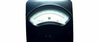
– using measuring instruments – wattmeters. Electrodynamic wattmeters are the most widely used.
Electrodynamic wattmeter device
Design elements:
A – fixed coil (series or current coil), works like an ammeter.
It is connected in series with the energy receiver (Rн) - therefore called a series coil or current coil.
B – a moving coil with additional resistance Rd (parallel or current coil), works like a voltmeter.
Together with Rd, it is connected in parallel to the energy receiver - therefore it is called a parallel coil or voltage coil.
The angle of rotation of the moving part of the wattmeter is always proportional to the measured power: i.e. the wattmeter scale is uniform.
The direction of rotation of the wattmeter pointer depends on the relative direction of the currents in its coils. Therefore, to correctly connect the wattmeter to the measured circuit, its terminals should be distinguished:
| generator | load |
| 1. current coil terminal A (series circuit) connected to the power source. 2.Voltage coil terminal B (parallel circuit) connected to series coil. | Two others. |
Generator terminals are marked with asterisks. These clamps are called generator clamps because when they are connected to each other and to one of the generator poles, the wattmeter pointer will deviate in the desired direction.
When the wattmeter is turned on correctly, the currents in its coils are directed from the generator terminals to the load terminals.
2. Power measurement in AC circuits
Single phase circuit
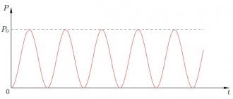
1.Active power
, where is the phase shift angle
between I
and
U.
In single-phase circuits, active power is measured by electrodynamic wattmeters.
They directly show the measured power taking into account the power factor - .
A reactive power
under production conditions, they are measured only in three-phase circuits.
| 2) If currents and voltages exceed the measurement limit of the wattmeter, then it is turned on through current and voltage measuring transformers. In this case, the power of the circuit is calculated as the product of the wattmeter reading and the transformation ratios of the CT and VT: . |
Three-phase circuit
In three-phase circuits active power
measured by electrodynamic and ferrodynamic wattmeters.
The number and switching circuits of wattmeters are determined depending on:
type of three-phase system (three or four wire),
its symmetry (uniform or uneven phase load)
· diagrams for connecting the phases of the energy receiver (star or triangle).
1)Three-wire system with symmetrical phase load
– single wattmeter method.
a) when connecting receivers (loads) with a star
| Conditions: The voltage system is symmetrical: . ·the load in all phases is the same: , . star connection: . |
The parallel circuit of the wattmeter is connected to phase voltage (), and through its series winding a phase current equal to linear current flows (), then the wattmeter shows power,
equal to the power of one load phase: .
Since the load is symmetrical, the total measured power is equal to triple the wattmeter reading:
Note
: — that’s why they replaced it, but .
Hence
b) when connecting the load into a triangle or when the zero point is inaccessible.
| Then the wattmeter is turned on with artificial nulldot – these are three equal resistances connected in a star, where ( - voltage coil resistance, — its additional resistance). |
1.Then the wattmeter reading Pw
equals the phase power, i.e.:
2. And the entire measured power is equal to triple the wattmeter reading:
.
Note
: when connecting the load into a triangle (replaced), and .
Then compare with a)
2)Three-wire system with asymmetric phase load
regardless of the connection diagram - the method of two wattmeters.
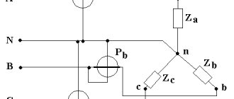
| (load connected in star) The active power of such a system is equal to the algebraic sum of the readings of two wattmeters: (linear!). |
The readings of these wattmeters are: (linear!).
? 3 phases, and 2 wattmeters. Proof:
1. The instantaneous power of a three-phase circuit can be expressed as the sum of the powers of the individual phases: . (1)
2. For the zero point of energy receivers connected by a star, according to Kirchhoff’s first law: ,
from where each of the linear currents can be expressed through the other two:
.
3.Substituting one of these expressions, for example for the current ic,
into formula (1), we get:
4. Let's move from instantaneous power to average (active): .
3)Four-wire system –
three wattmeter method.
| Then the active power will be equal to the algebraic sum of the readings of three wattmeters, each of which measures the power of one phase: . |
·You can also use one three-element wattmeter. It has three fixed coils and three movable ones, mounted on one axis.
If a wattmeter is connected to the circuit, then the torque acting on each of the moving coils will be proportional to the power of the corresponding phase. The resulting torque, equal to the sum of the individual torques, will be proportional to the active power of a four-wire three-phase current circuit. The angle of rotation of the moving part of the wattmeter will also be proportional to the same power.
Reactive power measurement in three-phase circuits
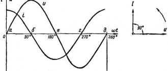
| For this purpose, single-phase (single-element wattmeters) are used. But here it is necessary to ensure phase shift between the current and voltage vectors, so that . |
This shift is obtained by turning on the wattmeter according to the following scheme ®Then the wattmeter shows the value of reactive power: |
That is, to measure reactive power, it is necessary to turn on the series circuit of the wattmeter in the same way as when measuring active power, and the parallel circuit to such a voltage to ensure a phase lag.
This condition is valid when measuring reactive power in both three-wire and four-wire systems. This circuit is called a voltage-replaced
.
Special cases
1) In a four-wire circuit -
three wattmeter method.
The reactive power of such a circuit is equal to the sum of the readings of three wattmeters of active power divided by: /See Fig. in active power/.
2) In a three-wire circuit
a) with uniform phase load
is used .
The total reactive power can be determined from the readings of two wattmeters using the formula:
,
i.e. it is determined by multiplying by the algebraic difference of the readings of two wattmeters,
where is the reading of the wattmeter included in the leading phase,
- readings of the wattmeter included in the lagging phase.
b) with uneven phase load
is used .
The total reactive power is determined by the formula: /See Fig./
3. Direct and indirect measurement of resistance in DC circuits
Direct resistance measurement
For this purpose special devices are used:
OhmmetersMeasure average resistances | MegaohmmetersMeasures large resistances (insulation resistance) |
Ohmmeters
Let's consider the device of an ohmmeter with serial connection
| The ohmmeter reading is affected by the voltage of the power source (battery) - it changes frequently. Therefore, before starting the measurement, it is necessary to calibrate the device - set the constant current ® |
The instrument pointer is set to the zero scale division using an adjusting resistor when closed
key
Kl
(then no current flows through - along the path of least resistance).
When the key is open
current flows through the device: , where is the adjusting resistor.
At constant values of U
, and the angle of rotation of the moving part depends only on the resistance, the values of which are plotted on the scale.
Special cases:
1) if (min), then I
and
(since ) — max.
2) if (max), then I
u = 0 (min)
Therefore, the scale looks like: . That is, such an ohmmeter is best used for measuring average resistances - up to several kOhms. (at low values it has low sensitivity).
And for ohmmeters with parallel connection
normal scale - . Used to measure small resistances.
Megaohmmeters
Disadvantage of ohmmeters:
Readings depend on battery voltage and require constant calibration.
Therefore, ratiometric measuring mechanisms are used in ohmmeters. Such devices are called megohmmeters
. In this case, a DC network or a special built-in generator is used for power supply.
| There are 2 moving coils with resistances and . included in series with . The currents flowing through the frames are equal: , . |
The angle of deviation of the ratiometer is determined by the ratio of the current within its framework (see the equation of the ratiometer scale): .
Since R 1,
R 2 and R d are
constant values for each ratiometer, the angle of deviation depends only on the measured resistance.
Modern megohmmeters are manufactured for voltages of 100, 250, 500, 1000 and 2500 V.
Indirect resistance measurement
Indirect method | ||
| ammeter method and voltmeter | compensation method (on potentiometer) | comparison method (pavement) |
Ammeter and voltmeter method
For
: average resistance measurements.
The basis of the method
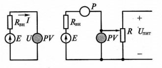
- measuring current and voltage in the circuit with the desired resistor and determining its resistance according to Ohm’s law: .
Two circuits for connecting an ammeter and a voltmeter are used.
1)
In the first circuit, since the ammeter and the measured resistance are connected in series, then
That is, the voltmeter readings are equal to the sum of the voltages on the ammeter and on the resistance.
Wire continuity - checking the integrity of an electrical circuit section
There are two ways to test wires with a multimeter, the use of which depends on the presence of a sound signal in the device. This function, if it exists, can be activated on different devices by different switch positions - so you need to pay attention to the icons that are drawn on the device body.
The buzzer is shown as a dot, to the right of which three semicircles are drawn, each of the subsequent ones larger than the previous one. You must look for such an icon either separately, or above the smallest number of the resistances, or near the diode icon, which is displayed as an arrow on a line, with its sharp end resting on another line perpendicular to the first.
If you turn the tester into dialing mode, it will beep if the resistance of the conductor being measured is less than 50 Ohms. In some devices this can be 100 Ohms, so if accuracy is needed, then you need to check the device data sheet.
You can see the wiring clearly in the video:
Then the measured resistance is:
, i.e.
A measurement error appears equal to .
Therefore, this circuit is used for measuring resistances that are larger than the resistance of the ammeter (100 times or more):
If , then â — it can be neglected, and .
2)
In the second circuit, since the voltmeter and the measured resistance are connected in parallel, then
That is, the ammeter readings are equal to the sum of the currents through the voltmeter and resistance.
How to measure resistance with a multimeter - basic rules and procedures
There are many situations when it will be useful to know how to measure resistance with a multimeter and whether it makes a difference which device is best to do this. Even if a person is not an avid radio amateur, when doing electrical work at home there is often a need to at least “ring” the wires - in fact, to make sure that the wire resistance is within acceptable limits.
reference Information
Documents • Laws • Notices • Document approvals • Contracts • Requests for proposals • Technical specifications • Development plans • Document management • Analytics • Events • Competitions • Results • City administrations • Orders • Contracts • Work execution • Protocols for consideration of applications • Auctions • Projects • Protocols • Budgetary organizations Municipalities • Districts • Education • Programs Reports
: • by references • Documentary base • Securities
Regulations
: • Financial documents
Resolutions
: • Categories by topic • Finance • cities of the Russian Federation • regions • by exact dates Regulations
Terms
: • Scientific terminology • Financial • Economic
Time
: • Dates • 2015 • 2016 Documents in the financial sector • in the investment sector • Financial documents - programs
Reasons for deterioration of insulation
There are the following number of reasons for the decrease in the resistance value of the insulating layer:
- Initially, poor quality of the shell material, manufacturing defects.
- Damage during electrical installation work.
- Deformation under the influence of tools and materials used for finishing.
- Under the influence of overheating, when the metal core heats up when connecting powerful devices, and the coating cracks, melts, and dries out.
- During freezing and thawing of soil masses, when the cable is laid in the ground.
- Exposure to environmental factors - sunlight, temperature changes, precipitation.
- Long-term operation.
Important! The most common cause of sheath damage is careless conductor fastening. The slightest contact with sharp edges of nail heads, screws, installation tools, as well as pulling wires through cable channels is accompanied by damage to the coating. Therefore, the frequency of measuring the insulation resistance of electrical wiring should correspond to the frequency of electrical installation work.
The inclusion of powerful electrical appliances in the network is a common cause of degradation of the insulating sheath of wires Source otoplenie-gid.ru
Education and science
Science
: Tests • Scientific and technological progress • Pedagogy • Work programs • Faculties • Methodological recommendations • School • Vocational education • Student motivation
Subjects
: Biology • Geography • Geology • History • Literature • Literary genres • Literary characters • Mathematics • Medicine • Music • Law • Housing Law • Land Law • Criminal Law • Codes • Psychology (Logic) • Russian Language • Sociology • Physics • Philology • Philosophy • Chemistry • Jurisprudence
Business and finance
Business
: • Banks • Wealth and prosperity • Corruption • (Crime) • Marketing • Management • Investments • Securities: • Management • Open Joint Stock Companies • Projects • Documents • Securities - control • Securities - valuations • Bonds • Debts • Currency • Real estate • (Rent) • Professions • Work • Trade • Services • Finance • Insurance • Budget • Financial services • Loans • Companies • State enterprises • Economics • Macroeconomics • Microeconomics • Taxes • Audit Industry
:
• Metallurgy • Oil • Agriculture • Energy
Construction
• Architecture • Interior • Floors and ceilings • Construction process • Building materials • Thermal insulation • Exterior • Organization and production management
Photo blogs
Art
• Children's creativity • Paintings • Art • Congratulations • Film review • Musical world • Russian rock
World
• People of the world • The world around us • My homeland is the USSR • Nature Channel • Stones and minerals • Cooking, food • Construction and architecture • Under construction • Transport • Weapons • Military transport
beauty
• Fashion Pandia.ru • Girls and Girls
School
• Tests for the Unified State Exam • Solver books • Unified State Examination • 10th and 11th grades • Various textbooks • 4th grade • Russian language grades 5-9 • 5th grade • 6th grade • 7th grade • 8th grade
Wisdom
• Cliparts • Quotes
Author Directory (private accounts)
AutoAuto service • Auto parts • Products for auto • Auto repair centers • Auto accessories • auto parts for foreign cars • Body repair • Auto repair and maintenance • Car chassis repair • Auto chemicals • oils • technical centers • Gasoline engine repair • auto electrical repair • Automatic transmission repair • Tire fitting BusinessAutomation of business processes • Online stores • Construction • Telephone communications • Wholesale companies LeisureLeisure • Entertainment • Creativity • Catering • Restaurants • Bars • Cafes • Coffee shops • Night clubs • Literature TechnologiesAutomation of production processes • Internet • Internet providers • Communications • Information technologies • IT companies • WEB studios • Website promotion • Software sales • Switching equipment • IP telephony | InfrastructureCity • Authority • District administrations • Courts • Utilities • Teen clubs • Public organizations • City information sites The sciencePedagogy • Education • Schools • Training • Teachers GoodsTrading companies • Trade and service companies • Mobile phones • Accessories for mobile phones • Navigation equipment |
Temperature coefficient values for some metals
| Metal | α | Metal | α |
| Silver Copper Iron Tungsten Platinum | 0,0035 0,0040 0,0066 0,0045 0,0032 | Mercury Nikelin Constantan Nichrome Manganin | 0,0090 0,0003 0,000005 0,00016 0,00005 |
From the formula for the temperature coefficient of resistance we determine rt:
rt = r.
Example 6. Determine the resistance of an iron wire heated to 200°C, if its resistance at 0°C was 100 Ohms.
rt = r = 100 (1 + 0.0066 α 200) = 232 Ohm.
Example 7. A resistance thermometer made of platinum wire in a room with a temperature of 15°C had a resistance of 20 ohms. The thermometer was placed in the oven and after some time its resistance was measured. It turned out to be equal to 29.6 Ohms. Determine the temperature in the oven.
