The fact that the rules require periodic measurement of grounding resistance is not just someone’s invention or whim, it is, first of all, a matter of the safety of human life. There are certain standards and measurements must comply with them. In this article we will look at how to measure ground resistance with a multimeter and other measuring instruments.
Before checking the grounding in a private home, it is very important that you understand the very essence of this procedure, why it is performed, what is the main purpose, why is it so necessary?
How to measure ground resistance using a multimeter and megohmmeter
“Diagnostics” of the circuit is done quite often.
The grounding value is measured both during its installation (the last, final stage of work) and in terms of monitoring the condition of the existing one. For example, to check the integrity of the rod, assess the possibility of using the circuit without reconstructing it with a significant increase in the load on the home electrical network, and in a number of other cases. And even more so, determining the resistance value is important if there are no protective devices (AV, RCD or differential circuit breaker) in the power supply circuit.
The fact is that all of the listed instruments are not suitable for carrying out official measurements. This requires special testing equipment. For “home” monitoring of the grounding condition, you can use any of the samples that you have on hand. Although the result will only be approximate, and this should be taken into account.
Why is resistance measured?
Carrying out measurements allows you to determine the value of the circuit resistance, which should not be higher than the established standards. If necessary, the resistance is reduced by increasing the contact area or the overall conductivity of the medium. For this purpose, the number of rods increases and the salt content in the soil increases.
It must be remembered that with the help of simple grounding it is only possible to reduce the voltage of the phase falling on the device body. To increase the reliability of protection, grounding is often installed together with a residual current device. The design and selection of a grounding device is carried out individually in each specific case. Its design is influenced by humidity, soil type and composition, as well as other factors.
Multimeter measurement
This universal device, if everything is done according to a standard, officially approved method, is not suitable for such purposes, as noted. In practice, a multimeter is used only for an approximate assessment of the grounding condition, identifying obvious breaks, that is, the lack of reliable contact of the corresponding conductor with the ground. How to do this correctly is described here.
Why is this type of measuring device used only in rare cases?
- A large measurement error does not give a true idea of the real resistance value.
- The standard (recommended) method cannot be used, since according to it the device must be connected to 4 points, which are also geographically separated. This cannot be done with a multimeter.
- No specialist will issue an official conclusion based on the results of measurements with such a device (documented). The reason is quite understandable - the regulations do not provide for the use of a multimeter when checking grounding.
However, there are situations when you cannot do without a multimeter. For example, in an area with fairly dense buildings. This does not allow measurements to be taken at large distances from the building. And according to the methodology, it should be within 30±10 m. You can learn more about how to measure resistance using a multimeter from the video:
How to prepare a multimeter
The goal of any measurement is to achieve maximum accuracy of readings. What needs to be done:
- choose a “good” multimeter (from friends, neighbors, and so on). Which one is better to choose for various purposes is described in this article. This means fairly new, and not produced decades ago, undamaged, with the highest possible accuracy class for this type of device;
- replace the battery. An old battery that is partially discharged will only increase the measurement error;
- perform calibration (if provided for a specific model).
How to prepare a workplace
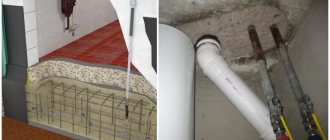
Even if the auxiliary electrode was initially installed when organizing grounding, it still needs to be found. Moreover, if the house was built many years ago, and the area around it has already been redeveloped, improved, and so on several times. Therefore, its “duplicate” must be supplied independently.
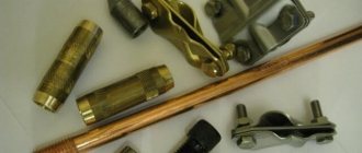
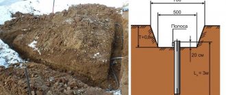
To measure resistance, any metal pin (the same reinforcing bar) with a cross-section of about 5 mm, which is driven into the ground at least 1.5 m at a distance of 7.5 ± 2.5 from the main one, is suitable. It is much easier to find it, especially since the location must be marked (with a sign, a symbol on the wall of the house). Although it is not difficult to determine visually - a metal wire (six or eight) often stretches towards it above the surface.
Where to measure resistance
Between the main ground pin and the newly installed (additional) one. The diagram is shown in the figure.
The measurement result allows you to understand how well the grounding rod meets the requirements that are placed on it. In essence, the total resistance of it and the soil is measured. The fact is that most of it is buried. During long-term use, the metal undergoes corrosion.
- The resistance of the additional rod is preliminarily determined. Its value is not taken into account when evaluating the result.
- The grounding R value should be Measured with a megohmmeter
The measurement principle is the same. The differences are only in some points.
- To obtain the most accurate readings, the device must be installed in a strictly horizontal plane. Skewing along any of the axes is not allowed.
- Preparing a megohmmeter (grounding resistance meter) comes down to checking it for suitability for measurements. This is quite simple to do (example: model M416).
- Switch to “Control”.
- The button is pressed and the handle is rotated. The arrow should be at 5 (±0.3). If the reading is different, the device is rejected.
- How to correctly connect a wire grounding resistance meter to the terminals, depending on the measurement circuit, is shown on its body.
There are quite a few methods for measuring ground resistance. They involve the use of various devices and circuits, and the optimal decision is made individually for a specific circuit. But for self-diagnosis of his condition at home, the two described above are sufficient.
If there are doubts about the correctness of the determination of the results, a large error, and so on, you should contact a professional. Grounding, given that it is an integral part of the power supply circuit, should not be neglected.
Taking measurements
And yet, in the question of how to measure grounding resistance, it is better to use a megohmmeter rather than a multimeter. The best option is considered to be a portable electrical measuring device M-416. Its operation is based on the compensation measurement method; for this purpose, a potential electrode and an auxiliary ground electrode are used. Its measuring limits are from 0.1 to 1000 Ohms, the device can be operated at temperatures from -25 to +60 degrees, power is provided by three 1.5 V batteries.
And now step-by-step instructions for the entire process on how to measure the resistance of the ground loop:
- Place the device on a horizontal, flat surface.
- Now calibrate it. Select the “control” mode, press the red button and, while holding it, set the arrow to the “zero” position.
- There is also some resistance in the connecting wires between the terminals; to minimize this influence, place the device closer to the ground electrode being measured.
- Select the desired connection diagram. You can check the resistance roughly; to do this, connect the terminals with jumpers and connect the device using a three-terminal circuit. For accurate measurements, the error caused by the connecting wires should be eliminated, that is, the jumper is removed between the terminals and a four-clamp connection diagram is used (by the way, it is drawn on the cover of the device).
- Drive the auxiliary electrode and probe rod into the ground to a depth of at least 0.5 m, keep in mind that the soil must be dense and not bulky. To hammer in, use a sledgehammer, the blows should be straight, without swinging.
- Clean the place where you will connect the conductors to the ground electrode with a file to remove paint. Use copper conductors with a cross section of 1.5 mm 2 as conductors. If you use a three-clamp circuit, then the file will act as a connecting probe between the ground electrode and the terminal, since a copper wire with a cross-section of 2.5 mm 2 is connected on its other side.
- And now we move on directly to how to measure grounding resistance. Select the range “x1” (that is, multiply by “1”). Press the red button and turn the knob to set the arrow to zero. For larger resistances, it will be necessary to select a larger range (“x5” or “x20”). Since we chose the “x1” range, the number on the scale will correspond to the measured resistance.
It is clear how grounding is measured in the following video:
How to check the quality of grounding
According to the Electrical Installation Rules, any electrical networks and equipment operating with voltages above 50 volts AC and 120 volts DC must have protective grounding. This applies to premises without signs of high-risk conditions. In hazardous areas (high humidity, conductive dust, etc.), the requirements are even stricter. But in this material we will mainly consider residential buildings. By default, we assume that there must be grounding.
When installing new power supply lines, grounding will be installed, and the owner of the premises can monitor this (or connect it himself). In the case when you live (work) in a ready-made room, the question arises: how to check the grounding? First of all, you need to make sure that you have it. Regardless of formal compliance with the EIC, this concerns the life and health of people.
Checking the presence and correct connection of protective grounding
At a minimum, you need to look into the switchboard of your apartment (house, workshop).
By default, we accept the condition: single-phase power supply. This will make it easier to understand the material.
The panel must have three independent input lines:
- Phase (usually indicated by a wire with brown insulation). Identified by an indicator screwdriver.
- Working zero (color marking - blue or cyan).
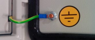
- Protective grounding (yellow-green insulation).
If the power supply input is designed this way, you most likely have a ground connection. Next, we check the independence of the working zero and protective grounding from each other. Unfortunately, some electricians (even in professional teams) use so-called grounding instead of grounding. The working zero is used as protection: a grounding bus is simply connected to it. This is a violation of the Electrical Installation Rules; using such a circuit is dangerous.
How to check whether grounding or grounding is connected as protection?
If the connection of the wires is obvious, there is no protective grounding: you have grounding. However, the apparent correct connection does not mean that there is a “ground” and that it is working. Checking grounding includes several stages. We start by measuring the voltage between the protective ground and the working zero.
We fix the value between zero and phase, and immediately carry out a measurement between the phase and protective grounding. If the values are the same, the “ground” bus has contact with the working zero after physical grounding. That is, it is connected to the zero bus. This is prohibited by the PUE; the connection system will need to be altered. If the readings differ from each other, you have the correct “ground”.
Further grounding measurements are carried out using special equipment. Let's look at this in more detail.
Ammeter and voltmeter method
Due to the fact that the circuit constantly operates with its entire volume in the ground, it is this that must be assessed when performing measurements. For this purpose, the main electrode and an additional electrode, to which alternating current is supplied, are immersed in the soil at a distance of at least 20 m from the grounding system to be monitored.
a) Schematic electrical diagram; b, c) Assembly diagrams with the MS-08 device
An electric current flows through a circuit constructed by an EMF source, wires and electrodes buried in the soil, the strength of which is determined using an ammeter. A voltmeter is installed on the surface of the grounding loop, cleaned to avoid the slightest error, and the contacts of the main grounding electrode, which measures the voltage drop on the line between the grounding loop and the main rod. By dividing the voltage by the current, the total resistance of the part of the circuit being tested is determined.
If there are no high requirements for measurement accuracy, then you can limit yourself to this value. If it is necessary to obtain accurate results, the calculated value should be adjusted by subtracting the resistance of the wires from it and taking into account the effect of the dielectric properties of the soil on the nature of spreading currents in the soil.
- The main advantages of this method are the simplicity and ease of taking measurements for private houses.
- Disadvantage: the required measurement accuracy is not ensured.
How does grounding work and why check its parameters?
Without going into details, we can say that grounding is needed to connect the electrical installation housing to the working zero. Looking at a few paragraphs above, you might think that this is absurd. In fact, what is meant is the possibility of current flowing from the protective grounding, through the physical ground (soil), to the working zero of the nearest substation. In fact, it will be a short circuit.
Accordingly, when a phase gets on the body of the electrical installation, the circuit breaker will operate, and there will be no electric shock.
Why is it necessary to check grounding resistance? To organize an emergency short circuit, a large current is required. If the resistance of the ground loop is too high, the current strength (in accordance with Ohm's law) will decrease and the circuit breaker will not operate.
Another danger of high resistance of the protective “earth” is that the resistance of the human body may be less. Then, if you touch an emergency electrical installation with your hand, you are guaranteed to be shocked by an electric shock.
Important! Grounding itself does not provide 100% protection against electric shock.
When a phase appears on the body of the electrical installation, part of the voltage will go to compensate for the leakage into the physical ground. If the remaining potential exceeds 50 volts, the danger will remain.
Likewise, a circuit breaker without grounding will not disconnect a phase if it hits the housing. It will only work when the zero is connected to the phase. Complete protection is provided by installing the machine and simultaneously connecting the protective ground circuit. The RCD also significantly increases the level of safety.
And finally, about what a ground loop is.
In short, these are several metal pins (under normal natural conditions - three), deeply immersed in the ground, connected by conductors to each other and the grounding bus in the building.
Checking protective grounding parameters
In addition to the obvious components of the protective “earth” system: such as a contact block, wires going to electrical installations, connection to a circuit in the ground, the earth itself plays an important role in providing protection. Accordingly, you need to make sure of the following:
- Between all elements of the circuit (pins, connecting bars, conductor into the room to the terminal block) there is a reliable electrical connection with minimal resistance.
- The voltage applied to the circuit (in the event of an accident) spreads across the physical ground with maximum current. This is only possible with good contact between the metal and the ground.
- The physical conditions of the terrain (ground) can ensure reliable contact even under poor (in terms of electrical current) conditions. Namely, drying out of the soil, cracking of the earth in the places where ground electrodes are installed.
Of course, no one takes measurements of parameters on every element of the grounding system. This will be required only in case of non-compliance with the standards, to find the so-called “weak link”.
By what principle is the protective ground loop checked?
It is necessary to create a complete analogue of a circuit that is known to work, and compare the indicators with the tested object. For this purpose, there are complexes for testing working grounding.
Let’s make a reservation right away: it is possible to make such a kit yourself, but it is expensive and impractical. Likewise, checking the parameters of protective grounding using standard measuring instruments (multimeter) will not show a reliable picture. And the tester will not be able to generate the high voltage necessary to measure spreading parameters. Therefore, it is better to either rent equipment or invite a specialist.
You can buy a set like this, but it is unlikely to pay for itself in the foreseeable future. Even taking into account that the frequency of checking grounding devices is once a year (for both residential and industrial facilities), it is easier to get one-time access to the equipment.
Typical device connection diagram
The principle of simultaneous use of a voltmeter-ammeter on the test section of soil works. There are three quantities: resistance, voltage, current. The parameters are calculated according to Ohm's law. We know the initial voltage, and the device maintains the current. Knowing the voltage drop between the test rods, we can calculate the ground loop resistance with high accuracy.
There is an error, but it is insignificant in comparison with the measured values. The contact resistance of the test electrode with the ground is generally taken as zero, provided that the rod is clean and not covered with corrosion.
Most modern devices immediately provide ready-made parameters for protective grounding, but in older (but no less reliable and accurate) designs, you will need to perform a simple division operation. In accordance with Ohm's law.
Checking grounding with a megohmmeter follows the same principle, only the measurement error will be higher. Still, the earth is not a conductor of electricity in the usual sense.
Review of techniques
Ammeter-voltmeter method
To carry out measurement work, it is necessary to artificially assemble an electrical circuit in which current flows through the ground electrode under test and the current electrode (it is also called an auxiliary electrode). This circuit also uses a potential electrode, the purpose of which is to measure the voltage drop during the flow of electric current through the ground electrode. The potential electrode must be located equally far from the current electrode and the ground electrode being tested, in an area with zero potential.
To measure resistance using the ammeter-voltmeter method, you must use Ohm's law. So, using the formula R=U/I we find the resistance of the ground loop. This method is well suited for measurements in a private home. To obtain the required measuring current, you can use a welding transformer. Other types of transformers are also suitable, the secondary winding of which is not electrically connected to the primary.
Using special devices
Let us immediately note that even for measurements at home, a multifunctional multimeter is not very suitable. To measure the resistance of the ground loop with your own hands, use analog instruments:
Let's look at how to measure resistance with the M-416 device. First you need to make sure that the device has power. Let's check the presence of batteries. If they are not there, you need to take 3 batteries with a voltage of 1.5 V. As a result, we get 4.5 V. The device, ready for use, must be placed on a flat horizontal surface. Next, we calibrate the device. We put it in the “control” position and, holding the red button, set the arrow to the “zero” value. For measurements we will use a three-clamp circuit. We drive the auxiliary electrode and the probe rod at least half a meter into the ground. We connect the device wires to them according to the diagram.
The switch on the device is set to one of the “X1” positions. We hold down the button and turn the knob until the arrow on the dial is aligned with o. The result obtained must be multiplied by the previously selected multiplier. This will be the desired value.
The video clearly demonstrates how to measure grounding resistance with the device:
More modern digital instruments can also be used, which greatly simplify the measurement work, are more accurate and retain the latest measurement results. For example, these are devices of the MRU series - MRU200, MRU120, MRU105, etc.
Working with current clamps
Ground loop resistance can also be measured using current clamps. Their advantage is that there is no need to disconnect the grounding device and use auxiliary electrodes. Thus, they allow you to quickly monitor grounding. Let's consider the operating principle of current clamps. An alternating current flows through the grounding conductor (which in this case is the secondary winding) under the influence of the primary winding of the transformer, which is located in the measuring head of the clamp. To calculate the resistance value, it is necessary to divide the EMF value of the secondary winding by the current value measured by the clamp.
At home, you can use current clamps S.A 6412, S.A 6415 and S.A 6410. Learn more about how to use current clamps. you can in our article!
It is better to use a megohmmeter to assess other safety factors
For example, insulation resistance. We are not talking about direct danger. That is, if you grab a wire with your hand in which the dielectric properties of the insulation are normal, you will not receive an electric shock.
But there is an additional danger: insulation breakdown under load. This unpleasant fact leads to malfunctions and, what’s more scary, to electrical circuit fires.
A megohmmeter for measuring insulation resistance is a voltage generator and a precision instrument in one housing.
The classic version (still used successfully today) produces voltage up to 2500 volts. Don't be afraid, the currents during operation are negligible. But you only need to hold on to the insulated handles of the measuring cables.
The high voltage potential easily reveals flaws in the insulation, and the meter needle shows the true resistance. Before starting work, you should turn off all voltage-supplying circuit breakers and get rid of residual potential: ground the wire.
To measure the breakdown between wires in one cable, two wires are used. They are connected to the cores of the disconnected cable, and measurements are taken. If the resistance is below normal, the cable is rejected. No one knows when a potential breakdown site will cause trouble.
To measure earth leakage, one wire is connected to the protective ground (in the area where the cable under test is laid), and the second to the central core. The voltage for testing should be higher. If the wire cannot be connected to ground, the measurement is carried out by applying a second electrode to the outer surface of the insulation.
If there is a screen (cable armor), a three-wire measurement system is used. the third wire is connected to the shield of the cable being tested.
The general scheme is exactly this, but each model of the device has its own instructions. Modern megohmmeters with a digital display are even easier to understand than the old pointer meters.
Using a megohmmeter, you can also test motor windings. But this is a separate topic. Information for those who think that all these devices are narrow-profile: using a shunt system, you can turn a megaohmmeter into a precision ohmmeter or voltmeter.
Internal structure of the measuring device
The main components of the device are:
- voltage generator (DC);
- measuring unit showing readings;
- measurement range switch (kOhm-MOhm), which makes it possible to change the output voltage by turning on various built-in resistor circuits;
- resistors are resistances that limit the flow of current.
An approximate diagram of the device of a megohmmeter with the designation of its main parts.
The internal generator in old-style devices operates from a manual drive due to the dynamo of the machine. Modern devices operate on batteries. Pointer (analog) devices display readings on a scale using two frames: one - working and the second - counteracting. The measuring unit of electronic megaohmmeters displays values on the display in digital form.
Appearance of a digital electronic megohmmeter for insulation diagnostics
Terminals for connecting probes, instead of being marked “L” and “Z”, may be marked “Rx” and “-”.