When working with electrical networks, measuring instruments play an important role in ensuring the safety of operating personnel, as well as in monitoring the condition of electrical appliances and their connection diagrams. The same applies to a device called a megohmmeter (formerly “megohmmeter”), designed to measure resistances that have very high values. This publication contains information about what a megohmmeter is, its scope of application, and how to use it. In this article we will talk about measuring resistance with a megohmmeter and look at step-by-step instructions.
Appearance of a device with a manually operated dynamo
Purpose of the device, design, principle of operation
The name of the device speaks for itself: “mega” means 106 or 1 million, “ohmmeter” means resistance measurement. Thus, it becomes clear that resistance measurements of millions of ohms or thousands of kohms are available with the device. Where and who might need such indicators? Basically, this is insulation and everything connected with it, that is, means that exclude the action of electric current where it is not necessary according to the electrical circuit or is unacceptable from a safety point of view.
Cables transmitting electricity, output transformer insulators, windings of electric motors of devices, machines and mechanisms must have reliable insulation that can prevent contact of conductors with each other, as well as with the device body, and prevent short circuits or electric shock to a person. Accordingly, the resistance value of the insulating means must be sufficiently high. A megohmmeter is designed to measure it. It can be used to determine that equipment needs to be replaced, repaired, or temporarily removed from work and dried out.
Internal structure of the measuring device
The main components of the device are:
- voltage generator (DC);
- measuring unit showing readings;
- measurement range switch (kOhm-MOhm), which makes it possible to change the output voltage by turning on various built-in resistor circuits;
- resistors are resistances that limit the flow of current.
An approximate diagram of the device of a megohmmeter with the designation of its main parts.
The internal generator in old-style devices operates from a manual drive due to the dynamo of the machine. Modern devices operate on batteries. Pointer (analog) devices display readings on a scale using two frames: one - working and the second - counteracting. The measuring unit of electronic megaohmmeters displays values on the display in digital form.
Appearance of a digital electronic megohmmeter for insulation diagnostics
Terminals for connecting probes, instead of being marked “L” and “Z”, may be marked “Rx” and “-”.
How to measure correctly
Before taking measurements, it is necessary to reduce the number of factors affecting the accuracy of the final results. For analog instruments with a dial indicator, this is, first of all, a horizontal arrangement of the housing. The magnitude of the error is also affected by the proximity of electromagnetic fields, so the devices should be placed as far as possible from them. This requirement must be observed for all types of meters.
Before testing, you should always calibrate the device. On induction, this can be done by turning the slider handle. Some electronic devices have a self-test function, so they will automatically fine-tune the operating conditions. A four-wire test circuit gives accurate results.
Operating principle of the device
The operation of the device is based on Ohm's law, known from a school physics course, where the current strength is directly dependent on voltage and resistance, which is reflected by the formula I = U/R.
The voltage is generated by the device itself. The measuring unit, in fact, is an ammeter that records the value of the current flowing through the circuit, but since the voltage supplied by the generator is known in advance, the divisions of the measurement scale are calculated and marked for kilo- and mega-ohms.
The insulation resistance test is carried out when the power is turned off, but the high voltage generated by the device can accumulate (for example, on capacitors) and collect into dangerous charges that can lead to electric shock to a person.
Review of megaohmmeter models and their manufacturers
The modern measuring equipment market offers a wide selection of devices from different brands. Through online stores you can purchase analog and digital megohmmeters in electrodynamic and electronic versions. Different models designed for making measurements in different ranges differ not only in operating parameters, but also in dimensions and price values. It is impossible to cover all models and their manufacturers in one publication, therefore, for orientation in the variety of products and their prices, domestic and foreign products are given as an example:
| A country | Device name | Model | price, rub. |
| Russia | ProfKip ES202/1g | Electrodynamic | 8 000 |
| Belarus | E6-26 | Electronic digital | 71 000 |
| Ukraine | ES0210/3 | Electrodynamic | 14 000 |
| Poland | Sonel MIC-2505 | Electronic digital | 60 000 |
| China | Uni-T UT-513 | Electronic digital | 16 000 |
The given cost values are averaged and cannot serve as a basis for placing orders and drawing up estimates for purchases. When choosing a measuring device, you cannot focus only on its cost or compact size. It is necessary to take into account quality (brand name, certificate of conformity, warranty) and technical parameters.
Digital electronic megohmmeter with a range from 500 to 5000 Volts
For example, the MY-40 megaohmmeter from the Japanese company YOKOGAWA is capable of operating in 4 ranges: 125, 250, 500 and 1000 V; it can be used to measure the resistance of ordinary conductors and powerful cables; it automatically discharges after the measurement is completed. Moreover, its cost is about 32 thousand rubles.
Some devices operate in the voltage range from 500 to 10,000 Volts and have an automatic selection of measurement limits, for example, Standard Electric 6212 IN. Its cost is approximately 55 thousand rubles.
Of course, powerful and expensive measuring instruments are more in demand at specialized enterprises, but for use in everyday life and small service centers it is enough to purchase an inexpensive compact electronic or electrodynamic analog megohmmeter.
How to measure ground loop resistance - a review of techniques
08/15/2016 no
Grounding resistance must be measured to make sure that it matches the requirements of the PUE (electrical installation rules) Ch. 1.8. as well as PTEEP pr. 3.3.1. Measurements taken in an electrical installation with a solidly grounded neutral (the voltage of which is below 1000V) must comply with the following standards. It doesn’t matter whether in winter or summer, the value should not exceed 8, 4 and 2 Ohms at voltages of 220, 380, 660 V (for sources with three-phase current), respectively, or 127, 220 and 380 V for sources with single-phase current. For electrical installations where an insulated neutral is used (voltage below 1000V), the resistance of the grounding loop must correspond to clause 1.7.104 of the PUE and is calculated using the formula Rз * Iз < 50 V. Below we will consider the main methods for measuring the loop, as well as instruments that can be used for this .
How to use
Before starting work, you need to perform phasing of the potential circuits (P1 and P2) and current circuits (T1 and T2). It is achieved by connecting circuits P1 and T1 on one side, P2 and T2 on the other side relative to the connected object.
For your information. The connection of current and potential circuits can be made both at the measurement point using the four-wire method, and they can be separated from each other when determining soil resistivity.
Installation of pins has its own characteristics:
- installation of electrodes is carried out along one line;
- a distance equal to five times the depth of immersion in the ground is maintained between the electrodes;
- the surface of the pins must be cleaned of dirt.
The electrode is connected to IS 10 to the sockets: T1, P1, T2, P2 in a certain sequence.
The sequence of connecting electrodes to the device
After the device is connected to the object being measured, you need to briefly activate the “Rx / ↵” button. The “MEASUREMENT” command will be displayed on the display, and the device will switch to the potential measurement mode at inputs P1 and P2.
Messages may appear on the screen:
- “OUT OF RANGE” – this means that the resistance of the measured section is >10 kOhm;
- “NO CIRCUIT” – a message indicating a defect that prevents the maintenance of the minimum current (poor contact, open circuit or uneven soil structure).
The user manual supplied with the device describes the methodology for two tests:
- two, - three, - or four-wire method - 2P, 3P, 4P;
- automatic determination of soil resistance – Rsp.
Important! The presence of an inductive or capacitive component in the active resistance of the object will change the readings on the display. They will also be taken into account in the reflected result.
First way
In the device menu, select the four-wire method by pressing the “MODE” button. Of the options presented, “4P” stands out. Next, use the “Rx / ↵” button to start the measurement. The numerical value of the ground resistance is displayed on the screen.
This method significantly refines the measurement results because it does not take into account the resistance of the measuring cords and the transition resistance of the connection points.
Four-wire diagram for connecting IS10 to a complex ground electrode
Second way
Is 10 resistance meters are used to determine the resistivity of the soil in which the protective circuit is located. Before grounding an object, it is advisable to know this indicator. It must be tested periodically on already protected objects.
When using the device, perform the following actions:
- the electrodes are located at a distance 5 times greater than the depth of the electrodes, maintaining straightness;
- pins are connected to outputs T1, P1 and P2, T2;
- the device is switched to “4P” mode and started with the “Rx / ↵” button;
- resistance readings RE are taken.
Using the formula, resistivity is found.
R beat = 2π * d * RE,
where d is the interelectrode interval, m.
Connecting IS 10 when determining resistivity
When making measurements with automatic determination of R beat, you need to:
- in the “MODE” option, select the “R beat” mode;
- compare the distances between grounding conductors stored in the device and, if necessary, change using the “SET. DIST";
- use the ▲ or ▼ cursors to set the distance from 1 to 99 m with an interval of 1 m;
- confirm the selection with the “Rx / ↵” button.
Attention! Measurements of this value are only permissible using the four-wire method. It starts automatically
The result is displayed in units: “Ohm*m”, “kOhm*m” or “MOhm*m”. The device remembers the amount of footage between the electrodes until the next measurements or until other values are entered.
The use of a device with an electrical clamp makes it possible to find out the distribution of currents as a percentage between individual ground electrodes in a multi-element circuit. Based on temporary monitoring data (during the preparation of annual measurement protocols), reflected in the grounding device passport, it is possible to assess the rate and nature of the aging of elements. On the same basis, changes in the soil structure along the perimeter of the contour are monitored.
The portable meter meets all modern requirements of measuring instruments. The simple interface and detailed information shown on the display make measurements a clear and simple process. A durable housing and convenient sockets for connecting electrodes contribute to long and trouble-free operation.
Review of techniques
Ammeter-voltmeter method
To carry out measurement work, it is necessary to artificially assemble an electrical circuit in which current flows through the ground electrode under test and the current electrode (it is also called an auxiliary electrode). This circuit also uses a potential electrode, the purpose of which is to measure the voltage drop during the flow of electric current through the ground electrode. The potential electrode must be located equally far from the current electrode and the ground electrode being tested, in an area with zero potential.
To measure resistance using the ammeter-voltmeter method, you must use Ohm's law. So, using the formula R=U/I we find the resistance of the ground loop. This method is well suited for measurements in a private home. To obtain the required measuring current, you can use a welding transformer. Other types of transformers are also suitable, the secondary winding of which is not electrically connected to the primary.
Using special devices
Let us immediately note that even for measurements at home, a multifunctional multimeter is not very suitable. To measure the resistance of the ground loop with your own hands, use analog instruments:
Let's look at how to measure resistance with the M-416 device. First you need to make sure that the device has power. Let's check the presence of batteries. If they are not there, you need to take 3 batteries with a voltage of 1.5 V. As a result, we get 4.5 V. The device, ready for use, must be placed on a flat horizontal surface. Next, we calibrate the device. We put it in the “control” position and, holding the red button, set the arrow to the “zero” value. For measurements we will use a three-clamp circuit. We drive the auxiliary electrode and the probe rod at least half a meter into the ground. We connect the device wires to them according to the diagram.
The switch on the device is set to one of the “X1” positions. We hold down the button and turn the knob until the arrow on the dial is aligned with o. The result obtained must be multiplied by the previously selected multiplier. This will be the desired value.
The video clearly demonstrates how to measure grounding resistance with the device:
More modern digital instruments can also be used, which greatly simplify the measurement work, are more accurate and retain the latest measurement results. For example, these are devices of the MRU series - MRU200, MRU120, MRU105, etc.
Working with current clamps
Ground loop resistance can also be measured using current clamps. Their advantage is that there is no need to disconnect the grounding device and use auxiliary electrodes. Thus, they allow you to quickly monitor grounding. Let's consider the operating principle of current clamps. An alternating current flows through the grounding conductor (which in this case is the secondary winding) under the influence of the primary winding of the transformer, which is located in the measuring head of the clamp. To calculate the resistance value, it is necessary to divide the EMF value of the secondary winding by the current value measured by the clamp.
At home, you can use current clamps S.A 6412, S.A 6415 and S.A 6410. Learn more about how to use current clamps. you can in our article!
How to check the ground loop yourself, the electric kettle method
The protective grounding circuit in the electrical wiring of a house or apartment is quite difficult to overestimate.
Firstly, it’s your safety, and secondly, it’s a long service life for almost all of your household electricity consumers. But quite often you come across articles on the Internet about how to properly check an installed circuit on your own. Let's take a look at these tips.
Tip #1 (from the electricians forum)
Quote: people, who are well versed in the intricacies of grounding circuits? I have some questions. Today we screwed up a circuit of 6 armaturins of 4 meters each. There was no special device for measuring resistance today. We did it in a rustic way. We connected a kettle through a phase and circuit (without a working zero) by 1.5 kW. The result is the following: Without load, the voltage is 247 V. We turn on the kettle, its voltage drop is 220 V. This means that there is a drop of 27 V on the circuit. The resistance of the kettle is 27 Ohms. If you calculate according to Ohm’s law, it turns out that the circuit resistance is slightly higher than 3 -x Ohm. Here is my question. How objective is this method? If I haven’t taken something into account, then I would like to understand what exactly? And then it started.
Advice, various advice, electricians with decades of experience. All the talk revolves around the resistance of the kettle, but they forgot about the grounding loop. I liked the fact that everyone remained unconvinced and everyone was sure that he was 100% right.
Tip No. 2 (how to check the ground loop with a tester)
Quote: you should not carry out such work without having the appropriate experience. Although the rules for their implementation are quite simple.
Everything ingenious is simple.
And now some advice from “experienced electricians”:
1. It is necessary to determine the phase contact in the socket. This is done with a special tester screwdriver with a phase indicator. The indicator touches the current-carrying wires being tested one by one, a finger touches the special contact on the handle of the screwdriver, the light comes on only when you touch the phase;
2. Using a measuring device in resistance measurement mode, the resistance between the neutral contact of the network and the ground contact is determined.
The method described above has a high error due to the low currents of the measuring device. A more correct method would be to use a special generator that supplies supply current to the grounding contact, and then the voltage in the grounding wire and the current strength are measured. The grounding resistance in this case is calculated according to Ohm's law.
We invite you to watch a video on how to check grounding on our channel
:
If, as a result of measurements, you find out that the result obtained deviates from the required norm, then you can take a number of measures to reduce the resistance:
- increase in soil acidity,
- replacement of soil at the location of the ground electrode,
- increase in grounding area.
You can find a lot of such advice. But what is surprising is that people who call themselves electricians do not think about how to check the ground loop correctly using methods and using special instruments, but how to carry out electrical measurements using some miracle methods (electric kettle method) or devices that are not intended for testing the ground loop.
This is equivalent to the fact that when you visit a doctor in a clinic, he will measure your body temperature using some kind of table, and listen to wheezing in your lungs by putting your ear to your back. And in the end, he will offer to buy a “health amulet” instead of medications.
Sounds funny? The “Kulibins” who are ready to prove any theory that they supposedly read in some “smart book” also look funny.
The consequences of the activities of such electricians do not look funny.
If you need to check the ground loop, contact an electrical measuring laboratory that has a certificate allowing such measurements. And do not forget to ask for a certificate of verification of the ground resistance meter.
You can order a ground loop test or modular grounding using the online form or by calling the numbers listed on our website www.energomag.net
+38(095)235-49-95,+38(096)262-98-48, +38(063)103-80-04
Delivery of grounding kits to any point in Ukraine by Nova Poshta on prepayment or cash on delivery.
If you are in doubt about your choice or don’t know how to choose a grounding kit, we will be happy to help you.
What is the frequency of measurements?
Visual inspection, measurements, and, if necessary, partial excavation of the soil must be carried out according to the schedule established at the enterprise, but at least once every 12 years. It turns out that when to take grounding measurements is up to you. If you live in a private house, then all responsibility lies with you, but it is not recommended to neglect checking and measuring resistance, since your safety directly depends on this when using electrical equipment.
When carrying out work, you must understand that in dry summer weather you can achieve the most realistic measurement results, since the soil is dry and the instruments will give the most accurate values of grounding resistance. On the contrary, if measurements are taken in autumn or spring in damp, humid weather, then the results will be somewhat distorted, since wet soil greatly affects the spread of current, which, in turn, gives greater conductivity.
If you want measurements of protective and working grounding to be carried out by specialists, then you need to contact a special electrical laboratory. Upon completion of the work, you will be given a grounding resistance measurement protocol. It displays the location of the work, the purpose of the ground electrode, the seasonal correction factor, and also at what distance the electrodes are located from each other. A sample protocol is provided below:
Finally, we recommend watching a video that shows how to measure the grounding resistance of an overhead line support:
So we looked at existing methods for measuring grounding resistance at home. If you do not have the appropriate skills, we recommend using the services of specialists who will do everything quickly and efficiently!
We also recommend reading:
Some basic parameters and rules
No matter what time of year you take measurements, the readings must always comply with the following standards:
| For single-phase voltage sources | For sources with three-phase voltage | Ground resistance value |
| 127 V | 220 V | 8 ohm |
| 220 V | 380 V | 4 ohm |
| 380 V | 660 V | 2 ohm |
It is recommended to take measurements under certain weather conditions when the earth is considered the most dense.
The ideal time is mid-summer (when the soil is dry) and mid-winter (when the ground is very frozen).
Wet soil will greatly affect the spread of current, so measurements taken in damp and humid weather in spring or autumn will be distorted.
There is another way to take measurements with a current clamp, but the best option would be to contact a specialized service. The electrical engineering laboratory will make all the necessary measurements and issue a corresponding protocol, which will indicate the location of the tests, the nature and resistivity of the soil, the measurement values with a seasonal correction factor.
The safety of using electrical energy depends not only on the correct installation of the electrical installation, but also on compliance with the requirements laid down in the regulatory documentation for its operation. The building's grounding loop, as an integral part of protective electrical equipment, requires periodic monitoring of its technical condition.
How does a grounding device work?
In normal power supply mode, the grounding loop is connected by a PE conductor to the housings of all electrical appliances, the potential equalization system of the building and is inactive: roughly speaking, no currents pass through it, with the exception of small background ones.
How does grounding protect people?
If an emergency occurs due to a breakdown of the electrical wiring insulation layer, dangerous voltage appears on the body of the faulty electrical appliance and flows through the PE conductor through the ground loop to the ground potential.
Due to this, the amount of high voltage transmitted to non-current-carrying parts should be reduced to a safe level that is not capable of causing electrical injury to a person in contact with the body of the faulty equipment through the ground.
When the PE conductor or ground loop is broken, there is no path for voltage to flow and the current will begin to flow through the human body. caught between the potentials of a damaged household appliance and the ground.
Therefore, when operating electrical equipment, it is important to maintain the grounding loop in good condition and monitor its condition with periodic electrical measurements.
How does a grounding device malfunction?
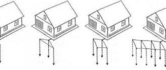
In a new, serviceable circuit, the electric current of the accident through the PE conductor enters the current-carrying electrodes, which are in contact with the ground with their surface and through them uniformly goes to the ground potential. In this case, the main flow is evenly divided into its component parts.
As a result of prolonged exposure to the aggressive soil environment, the metal of the current conductors becomes covered with a surface oxide film. The beginning of corrosion gradually worsens the conditions for the passage of current and increases the electrical resistance of the contacts of the entire structure. Rust that forms on steel parts is usually general, and in some areas it has a pronounced local character. This is due to the uneven presence of chemically active solutions of salts, alkalis and acids that are constantly present in the soil.
The resulting corrosion particles in the form of individual flakes move away from the metal and thereby stop the local electrical contact. Over time, there become so many such places that the circuit resistance increases and the grounding device, losing electrical conductivity, becomes unable to reliably discharge dangerous potential into the ground.
Only timely electrical measurements can determine the moment of the onset of a critical state of the circuit.
Principles underlying the measurement of grounding device resistance
The method for assessing the technical condition of a circuit is based on the classical law of electrical engineering, identified by Georg Ohm for a section of a circuit. For this purpose, it is enough to pass current from a calibrated voltage source through the controlled element and measure the passing current with a high degree of accuracy, and then calculate the resistance value.
Ammeter and voltmeter method
Since the circuit operates in the ground with its entire contact surface, it should be assessed when measuring. To do this, electrodes are buried in the soil at a short distance (about 20 meters) from the controlled grounding device: main and additional. They are supplied with current from a stabilized alternating voltage source.
An electric current begins to flow through the circuit formed by wires, an EMF source and electrodes with an underground conductive part of the soil, the value of which is measured with an ammeter.
A voltmeter is connected to the surface of the ground loop cleaned to bare metal and the contact of the main ground electrode.
How to measure ground resistance using a multimeter and megohmmeter
“Diagnostics” of the circuit is done quite often. The grounding value is measured both during its installation (the last, final stage of work) and in terms of monitoring the condition of the existing one.
For example, to check the integrity of the rod, assess the possibility of using the circuit without reconstructing it with a significant increase in the load on the home electrical network, and in a number of other cases. And even more so, determining the resistance value is important if there are no protective devices (AV, RCD or differential circuit breaker) in the power supply circuit.
A multimeter is not very suitable for measuring ground R. Why is explained below. There are recommendations on the Internet that it is better to use analog devices M-416, F4103 (M1), ISZ-2016, MS-08 or digital devices of the MRU series (models 105, 120 or 200). What the difference is is unclear. Their connection diagrams are similar.
The fact is that all of the listed instruments are not suitable for carrying out official measurements. This requires special testing equipment. For “home” monitoring of the grounding condition, you can use any of the samples that you have on hand. Although the result will only be approximate, and this should be taken into account.
Taking measurements
Ammeter-voltmeter method
To carry out measurements, an electrical circuit is created in which current flows through the grounding device being tested and a current conductor (also called an auxiliary electrode). The circuit also contains a potential electrode, the task of which is to measure the voltage drop when current flows through the ground electrode. The potential conductor is located in an area with zero potential - at an equal distance from the auxiliary electrode and the grounding system being tested.
For resistance measurements, Ohm's law is used (formula R=U/I). Using this technique, resistance is most often determined in a private home. To obtain the required current, use a transformer for welding or any other equipment where there is no electrical connection between the secondary and primary windings.
Using special equipment
At home, they rarely use an expensive multifunctional multimeter. The most commonly used analog devices are:
- MS-08;
- F4103-M-1;
- M-416;
- AES-2016.
One of the most common devices for testing resistance is MS-08. For measurements, two electrodes are installed at a 25-meter distance from the grounding device. The current in the chain is generated by the action of a generator rotated manually using a gearbox. As a result of activating the circuit and connecting the device, the resistance of the auxiliary grounding conductors is compensated. If this does not happen, the soil near the additional grounding device is artificially moistened. Measurements are carried out in various ranges until the tester shows significant indicators (and they should not differ after final installation).
The M-416 measuring device is comfortable to use due to its low weight and the scale where the received data is recorded. M-416 includes semiconductors with autonomous power supply.
Example of using the M-416 device:
- We check that the device has power. The device must contain three batteries - each 1.5 volts.
- Place the device on a flat surface.
- We calibrate the equipment. We set up the M-416 for control and, by pressing the red button, set the arrow to the zero position.
- We select a three-clamp circuit for measurement.
- We dig the auxiliary conductor and probe rod into the ground at least 50 centimeters.
- We connect the wires to the electrode and the probe rod according to the diagram.
- We place the switch in one of the “X1” positions. While holding the key, scroll the knob until the arrow on the scale reaches zero. We multiply the result by the previously calculated factor. The final value is the desired value.
Working with current clamps
Loop resistance is also determined using current clamps. Their main advantage is that there is no need to disconnect the grounding switch and use auxiliary conductors.
An alternating current passes through the grounding conductor, which is the secondary winding. The flow of current is facilitated by the primary transformer winding located in the measuring head of the device. To determine the resistance indicator, we divide the EMF data of the secondary winding by the current value obtained when measuring with clamps.
As an example of current clamps, let's take the CA 6415 tester. It is equipped with a liquid crystal monitor. No additional conductors are needed to measure resistance. There is also no need to disconnect the PE conductor from the electrodes.
Insulation resistance measurement
To measure the insulation resistance, use a special device - a megger. The device consists of several elements:
- continuous current generator equipped with a manual drive;
- additional resistance;
- magnetoelectric ratiometer.
Before starting testing work, you should make sure that the facility is disconnected from the power supply. We remove dust and dirt from the insulating layer. After this, we measure for approximately 3 minutes. As a result, we obtain data on residual charges.
We connect the megger to the electrical circuit or equipment with separate conductors. The insulation has high resistance. Its level most often exceeds 100 megaohms.
Note! The insulation resistance is measured after the arrow reaches a stable position
Multimeter measurement
This universal device, if everything is done according to a standard, officially approved method, is not suitable for such purposes, as noted. In practice, a multimeter is used only for an approximate assessment of the grounding condition, identifying obvious breaks, that is, the lack of reliable contact of the corresponding conductor with the ground. How to do this correctly is described here.
Why is this type of measuring device used only in rare cases?
- A large measurement error does not give a true idea of the real resistance value.
- The standard (recommended) method cannot be used, since according to it the device must be connected to 4 points, which are also geographically separated. This cannot be done with a multimeter.
- No specialist will issue an official conclusion based on the results of measurements with such a device (documented). The reason is quite understandable - the regulations do not provide for the use of a multimeter when checking grounding.
However, there are situations when you cannot do without a multimeter. For example, in an area with fairly dense buildings. This does not allow measurements to be taken at large distances from the building. And according to the methodology, it should be within 30±10 m. You can learn more about how to measure resistance using a multimeter from the video:
How to prepare a multimeter
The goal of any measurement is to achieve maximum accuracy of readings. What needs to be done:
- choose a “good” multimeter (from friends, neighbors, and so on). Which one is better to choose for various purposes is described in this article. This means fairly new, and not produced decades ago, undamaged, with the highest possible accuracy class for this type of device;
- replace the battery. An old battery that is partially discharged will only increase the measurement error;
- perform calibration (if provided for a specific model).
How to prepare a workplace
Even if the auxiliary electrode was initially installed when organizing grounding, it still needs to be found. Moreover, if the house was built many years ago, and the area around it has already been redeveloped, improved, and so on several times. Therefore, its “duplicate” must be supplied independently.
To measure resistance, any metal pin (the same reinforcing bar) with a cross-section of about 5 mm, which is driven into the ground at least 1.5 m at a distance of 7.5 ± 2.5 from the main one, is suitable. It is much easier to find it, especially since the location must be marked (with a sign, a symbol on the wall of the house). Although it is not difficult to determine visually - a metal wire (six or eight) often stretches towards it above the surface.
Where to measure resistance
Between the main ground pin and the newly installed (additional) one. The diagram is shown in the figure.
The measurement result allows you to understand how well the grounding rod meets the requirements that are placed on it. In essence, the total resistance of it and the soil is measured. The fact is that most of it is buried. During long-term use, the metal undergoes corrosion.
In addition, aggressive chemical compounds come into direct contact with it, which causes an oxide film to appear on the surface of this electrode. As a result, there is a decrease in the ability of the rod to discharge electric current into the ground (induced, resulting from an insulation breakdown or in another emergency). Consequently, such grounding is no longer able to ensure the safety of the user (service personnel).
- The resistance of the additional rod is preliminarily determined. Its value is not taken into account when evaluating the result.
- The R value of the ground must be < 0.05 Ohm.
- With this measurement method, the error is within 15%.
- Diagnostics of the circuit must be carried out under favorable weather conditions.
“Manual” for measuring the resistance of a grounding device
Why do this
Measuring ground resistance provides basic information about its performance. And since the main means of protecting electrical installations, as a rule, is the grounding device (GD), it is impossible to do without assessing its main characteristics both during commissioning and during periodic and control tests during operation.
Basic concepts allow you to speak the same language. You understand and you are understood.
According to PUE-7, the resistance of the grounding device is the ratio of the voltage at the charger to the current flowing from the ground electrode into the ground. Please note that a grounding device is a combination of a ground electrode and grounding conductors. That is, when measuring, it is necessary to determine the resistance of the entire circuit that makes up the grounding electrode (the term “grounding loop” is common, denoting this circuit, although it is not officially fixed in PUE-7).
In relation to chargers , a distinction is made between commissioning tests and operational tests.
In the first case, resistance measurements are made to determine whether the charger can be put into operation (along with other types of tests, if they are provided for by regulatory documents). In the second case, the performance of the already commissioned grounding at a given time is assessed. The need for operational tests arises both due to the aging of the charger and due to seasonal changes in grounding parameters, associated, for example, with fluctuations in soil moisture.
Despite the fact that resistance is measured, the use of conventional ohmmeters to test the charger is practically useless. Special instruments are produced for this type of measurement. These are called ground resistance meters or simply ground meters.
Measurements can be carried out on direct current, alternating current of industrial frequency (for our country this is a frequency of 50 Hz), as well as alternating current of high frequency (frequency of the order of hundreds of Hz and higher). Since the basis of the electrical power industry is still alternating current, measurements of grounding parameters on direct current, with the exception of some very highly specialized cases, are not carried out. When measuring at a frequency of 50 Hz, there is a problem of interference from stray currents at the same frequency caused by the operation of electrical installations or even power lines nearby. This problem was solved by the ability to manually vary the operating frequency (for example, such a solution was used in the Soviet MS-08 device). Measurements using high-frequency currents are very relevant due to the wide distribution of various types of nonlinear loads, which leads to an abundance of harmonics in the grounding circuit.
Modern devices use resistance measurement using current pulses with a “meander” shape, the frequency of which ranges from 100 to 300 Hz (for example, the very popular ZhG-4300 device uses a frequency of 128 Hz). Thus, it is possible to tune out interference with a frequency of 50 Hz and simulate real conditions when the current has many harmonics. Additional protection against interference is achieved through digital signal processing, in particular, the use of fast Fourier transform.
The voltage amplitude at the terminals of charger resistance meters, as a rule, should not exceed 42 V. This ensures the safety of the measurement procedure for personnel.
How to measure
For many years, the MS-08 device was a real “workhorse” for measuring charger resistance. Its production began back in 1957, and the device is still used in some places. Moreover, you can find new copies in online stores; they are sold at a price even higher than modern digital meters made in China. By the way, I couldn’t find any mention of the MC-08 being discontinued; perhaps this legend is still in production?
An important advantage of the MS-08 is that it does not require batteries. When measuring, it is necessary to turn the handle of a dynamo that produces alternating current. By changing the frequency of rotation of the knob, you can vary the frequency at which measurements are taken in order to tune out interference. Not only is the dynamo mechanically connected to the handle, but also a commutator that performs the function of a rectifier. The switch changes the polarity of the connection of the measuring device in phase with the current generated by the dynamo. Thanks to this, interference is suppressed quite effectively. The device has three measurement ranges: up to 10 Ohms, up to 100 Ohms and up to 1000 Ohms.
In 1972, the USSR launched the production of more advanced measuring instruments M416, where it was no longer necessary to turn the knob. Interference suppression was carried out using a synchronous detection method. It was possible to measure resistance in the range from 0.1 to 1000 Ohms; 4 measurement ranges were provided. Currently, the “classic” analog M416 is not produced, however, under this index, a digital charger resistance meter is now being supplied to the market, which, however, has nothing in common with its namesake.
Of the Soviet-style analog resistance meters, the F4103-M1 device is still produced and widely used. It can be powered either from galvanic cells or from an external source. Measurements are carried out at a frequency of about 300 Hz (not adjustable). The device is capable of measuring resistance from 0 to 15000 Ohms, 10 ranges are provided.
Modern devices, as a rule, have a digital display, but there are still specialists for whom dial indicators are more comfortable. They will appreciate the inexpensive SEW 1805R with dial indicator. The advantages of a device that measures resistance from 0.1 to 2000 Ohms (3 ranges) include the low current used in measurements (2 mA versus 80 - 200 mA for other devices), which in some cases allows you not to disconnect the circuits being measured. Another feature is the high operating frequency of 820 Hz. The disadvantage of the device is that it only supports 2-wire and 3-wire measurement schemes (this will be discussed in more detail later).
The IS-20 device is optimal for carrying out measurements in difficult conditions. Its advantages include ergonomic design, IP54 protection level, and multiple power supply options. The range of measured resistances is from 1 microOhm to 9.99 kOhm. Measurement data can be transferred to a computer wirelessly via Bluetooth. Operating frequency - 128 Hz, in two-wire measurement mode - 512 Hz. It is important that the device is manufactured in Russia, which is critical for a number of applications.
The modern “workhorse” of charger resistance measurements is the Iron Harry ZG-4300 device. It is very light (0.9 kg with batteries) and has a comfortable ergonomic design. You can measure resistance from 0.05 Ohm to 20 kOhm, there are 5 ranges.
The top models of meters include the MRU-200 device. It is capable of measuring protective earth resistance ranging from 0 to 19.99 kOhm. The degree of protection is IP54, a built-in NiMH battery with a capacity of 4.2 Ah is provided - all this is a significant advantage when working “in the field”. In addition to measuring the resistance of protective grounding, the device can also determine the grounding resistance of a lightning protection system using the pulse method, from 0 to 199 Ohms. This charger resistance meter is produced in the European Union, namely in Poland.
It should be noted that the listed devices, in addition to the main function, may have additional ones, for example, measuring soil resistivity or measuring leakage current resistance.
How to measure
The most common are classical methods for measuring charger resistance, based on the use of a voltmeter and ammeter with subsequent calculation of resistance according to Ohm's law. You can read more about these methods here.
The advantages of classical methods include the possibility of using them for almost any power supply system. Disadvantages - the need to disconnect the grounding from the electrical installation for the duration of measurements, the influence of stray currents on the accuracy of measurements.
Classic methods are divided into two-, three- and four-wire. Due to low accuracy, the two-wire method is practically not used. The three-wire method is simple to implement, but is inferior in accuracy to the four-wire method.
In the event that the measured resistance of the charger must be obviously lower than 5 Ohms, it is recommended to use only the four-wire method.
The measuring device has potential terminals P1 and P2 and current terminals T1 and T2. With the four-wire method, different wires go from P1 and T1 to grounding, which are connected directly at the grounding terminals. When measuring using the three-wire method, terminals P1 and T1 are connected by a jumper and one wire goes from them to ground. If the device is initially intended only for measurements using the three-wire method, then one terminal is provided for connecting to ground with one wire.
Terminals P2 and T2 are connected, respectively, to the so-called potential pin and current pin. It is recommended to bury the measuring pins into the ground by at least 0.5 m. Typically, the current and potential pins are lined up in a single line with the charger.
In order to correctly determine the distance between the pins, it is necessary to determine the maximum diagonal size of the ground electrode D. The potential pin is installed at a distance of 1.5 D, but not less than 20 m from the ground electrode. The current pin is installed at a distance of no more than 3D, but not less than 40 m from the ground electrode.
But one measurement is usually not enough to obtain an accurate result. The reason is the unevenness of the soil structure. Therefore, the potential pin is set several times at a distance from 20 to 80% of the original distance between the potential and current pin. In this case, the resistance is measured each time. The more points, the better; for high accuracy, a step of 10% is enough. The results obtained are plotted on a graph. If the graph has the shape of a smoothly increasing curve, then the final result is taken as resistance in the area where the difference between adjacent points does not exceed 5%. If the graph shows a significant steepness or a more complex shape, then the measurements must be repeated, changing the direction of the line on which the pins are placed. It may also be necessary to increase the original distances by 1.5 - 2 times.
Electrodeless method
It is not always possible to install current and potential pins. For example, in permafrost conditions or when there is simply no room for pins on the site. At the same time, measuring the grounding of power lines in permafrost areas is carried out, as a rule, precisely during the period of greatest soil freezing. It is also not always possible to disconnect the charger from the electrical installation during measurements. Then an electrodeless measurement method is used in accordance with GOST R 50571.16-2007, based on the use of current clamps. It is described in detail here.
The charger is supplied from a measuring generator with an alternating current of a given voltage at a frequency different from the mains frequency. The current strength in the ground wire is measured by special current clamps, which are sensitive only to the frequency at which the measuring generator operates. Since the voltage value on the charger is precisely known, by measuring the current, it is possible to calculate, according to Ohm's law, the resistance of the charger.
It should be noted that, despite all its convenience, the electrodeless method is inferior in measurement accuracy to properly organized measurements using the classical method. In particular, to supply alternating current for measurement into a circuit, a device similar in principle to a current clamp is used. To ensure the required level of induction, an operating frequency of about 3 kHz is used, which also gives an error.
It can be considered that the electrodeless method gives an estimate of the value of the charger resistance from above. That is, the actual resistance value will not exceed the readings of the device. From a safety point of view, this is normal - the lower the actual resistance value, the better.
The disadvantage of the electrodeless method is that it can only be directly applied to TT systems and mesh-grounded TN systems. Conventional TN systems will require the temporary installation of a jumper between neutral and earth. The power in the entire building where grounding is installed will have to be turned off during measurements and there will be no advantages over the classical method.
Examples of electrodeless measurement equipment include the FLUKE-1630-2 and Greenlee CMGRT-100A. The cost of such systems is 5 - 10 times higher than that of devices for measuring resistance using the classical method.
Requirements for instruments, documentation and laboratory personnel
Since the state of health, and even the lives of people, depends on the serviceability of grounding, the devices discussed in the article must be certified for use on the territory of the Russian Federation and be verified. The verification period for a charger resistance meter is usually 1 year, in some cases up to 2 years. General requirements for the qualifications of employees working with a charger resistance meter are usually given in the technical documentation for the device.
If measurements are carried out as part of routine maintenance of an electrical installation, documentation on them is drawn up in accordance with Chapter. 1.8 PTEEP.
In order for the laboratory where the device is used to operate within the framework of the Unified Compliance System, its organizational structure and qualifications of employees must comply with the requirements of SDAE-04-2010. The laboratory must be certified according to the rules given in SDAE-01-2010 and POTEE must have a Certificate of Registration of the Electrical Laboratory.
In the event that measurements are carried out by an accredited laboratory, a measurement protocol is drawn up in accordance with GOST R 58973-2020. This GOST gives general rules for the preparation of documentation. A specific sample of the charger resistance measurement protocol form was named EL-8a (). This form meets the requirements of GOST R 58973-2020, however, it was not introduced by any federal regulation. It’s just that at one time a standard set of test report forms was created in *.doc format. This is convenient, however, the legal requirement to use this particular form is not enshrined anywhere.
It is advisable to attach a copy of the laboratory certification certificate to the measurement protocol, as well as a copy of the verification certificate of the measuring device. These documents will immediately give an understanding of the competence and professionalism of the workers and the company that performed the measurements.
How many ohms should there be and how often should it be measured?
Some standards for grounding resistance are given in the table:
| Type of grounding | Resistance, Ohm, no more | Regulatory document | Possibility of increase in exceptional cases |
| Electrical installations up to 1 kV with insulated neutral | 4 | clause 1.7.65 PUE-7 | 10 Ohm with a power of generators and transformers not exceeding 100 kVA |
| General resistance to spreading of grounding conductors of a three-phase overhead line 380 V | 10 | clause 1.7.64 PUE-7 | 0.01ρ times with earth resistivity ρ over 100 Ohm*m, but not more than 10 times |
| Repeated resistance to spreading of grounding conductors of a three-phase overhead line 380 V | 30 | clause 1.7.64 PUE-7 | 0.01ρ times with earth resistivity ρ over 100 Ohm*m, but not more than 10 times |
| Grounding the neutral of a generator or transformer in a three-phase 380 V network | 4 | clause 1.7.101 PUE-7 | 0.01ρ times with earth resistivity ρ over 100 Ohm*m, but not more than 10 times |
PTEEP recommends carrying out a full inspection of the charger with opening of the soil once every 12 years. Grounding devices for overhead line supports less than 1000 V should be checked more often - once every 6 years. In addition, grounding devices should be checked after repairing supports.
Standards RD 153-34.0-20.525-00 require a complete check of the charger at electric power facilities once every 12 years. However, after a short circuit or emergency situation occurs at the facility, an inspection of the charger in the accident zone and in the adjacent sections of the charger must be carried out. In addition, which is especially important in light of ongoing efforts to digitalize the electric power industry, it is recommended to check the memory after each reconstruction, especially if electronic and microprocessor devices are installed. That is why, as modern technologies are introduced in the electric power industry, devices for measuring charger resistance will be increasingly in demand.
You can get a free grounding calculation or ZANDZ using the buttons below.
See also:
Electrolytic grounding in permafrost soil...
Electrolytic grounding in central Russia...
Analysis of the regulatory document FEDERAL STANDARDS AND ...
Can stainless grounding be checked with a magnet?
Measurement with a megohmmeter
The measurement principle is the same. The differences are only in some points.
- To obtain the most accurate readings, the device must be installed in a strictly horizontal plane. Skewing along any of the axes is not allowed.
- Preparing a megohmmeter comes down to checking it for suitability for measurements. This is quite simple to do (example: model M416).
- Switch to “Control”.
- The button is pressed and the handle is rotated. The arrow should be at 5 (±0.3). If the reading is different, the device is rejected.
- How to correctly connect wires to the megohmmeter terminals, depending on the measurement circuit, is shown on its body.
It should be recalled that before starting measurements, it is necessary to visually inspect the ground loop for the integrity of all connections, seams, and so on. And only if no defects are identified, you can start working with the device.
There are quite a few methods for measuring ground resistance. They involve the use of various devices and circuits, and the optimal decision is made individually for a specific circuit. But for self-diagnosis of his condition at home, the two described above are sufficient.
If there are doubts about the correctness of the determination of the results, a large error, and so on, you should contact a professional. Grounding, given that it is an integral part of the power supply circuit, should not be neglected.
Good luck with your measurements!
electricremont.ru
Safe operation of the megohmmeter
Any measurements should be made only with a working megohmmeter. The device must be tested in a laboratory where its own insulation and all components are checked. An increased voltage is used for testing, after which the megohmmeter is given permission to operate for a certain, limited period.
For verification purposes, the megohmmeter is sent to a metrology laboratory, where specialists determine its accuracy class. Passage of control measurements is confirmed by a stamp applied to the body of the device. During further operation, the safety and integrity of the mark must be maintained, especially the date and number of the specialist who carried out the verification. Otherwise, the device will automatically fall into the faulty category.
The correct application area also ensures safety when working with the megohmmeter. Before each measurement, the output voltage value is determined. The device is primarily used for insulation testing. For this purpose, extreme conditions are created for the area being tested, when not the rated voltage, but an overestimated voltage is supplied. The time period is also quite long. This contributes to the timely identification of possible defects and their prevention in subsequent operation.
Each circuit to be tested has its own characteristics that affect the safe operation of the megohmmeter. Therefore, before applying high voltage to the desired area, it is necessary to eliminate all malfunctions and breakdowns of the constituent elements. Modern equipment is literally saturated with semiconductors, capacitors, measuring and microprocessor instruments. They are not designed for the high voltage generated by the megohmmeter generator. Before testing, all such devices are bypassed or completely removed from the circuit. At the end of the measurements, the circuit is restored and brought into working condition.
Checking the presence and correct connection of protective grounding
At a minimum, you need to look into the switchboard of your apartment (house, workshop).
By default, we accept the condition: single-phase power supply. This will make it easier to understand the material.
The panel must have three independent input lines:
- Phase (usually indicated by a wire with brown insulation). Identified by an indicator screwdriver.
- Working zero (color marking - blue or cyan).
- Protective grounding (yellow-green insulation).
If the power supply input is designed this way, you most likely have a ground connection. Next, we check the independence of the working zero and protective grounding from each other. Unfortunately, some electricians (even in professional teams) use so-called grounding instead of grounding. The working zero is used as protection: a grounding bus is simply connected to it. This is a violation of the Electrical Installation Rules; using such a circuit is dangerous.
How to check whether grounding or grounding is connected as protection?
If the connection of the wires is obvious, there is no protective grounding: you have grounding. However, the apparent correct connection does not mean that there is a “ground” and that it is working. Checking grounding includes several stages. We start by measuring the voltage between the protective ground and the working zero.
We fix the value between zero and phase, and immediately carry out a measurement between the phase and protective grounding. If the values are the same, the “ground” bus has contact with the working zero after physical grounding. That is, it is connected to the zero bus. This is prohibited by the PUE; the connection system will need to be altered. If the readings differ from each other, you have the correct “ground”.
Further grounding measurements are carried out using special equipment. Let's look at this in more detail.
Checking the grounding of outlets
If you bought a house or apartment, and all the electrical parts in the room were already installed before you, how to check the grounding in the outlet?
To begin, we suggest you perform a visual inspection. Disconnect the input circuit breaker for the apartment and disassemble one socket. It must have a corresponding terminal to which the grounding conductor is connected; as a rule, it is yellow-green in color. If all this is present, then the outlet is grounded. If you find only two wires - brown and blue (phase and neutral), then the outlet does not have a protective ground.
At the same time, the presence of a yellow-green conductor does not mean that the grounding is working properly.
The efficiency of the circuit can be determined with a special device, which no electrician can do without, a multimeter. The algorithm for this check is as follows:
- In the distribution panel, turn on the input circuit breaker, that is, there must be voltage in the sockets.
- Set the device to voltage measurement mode.
- Now you need to touch the phase and neutral contacts with the probes of the device and measure the voltage between them. The device should display a value of about 220 V.
- Make a similar measurement between the phase and ground contacts. The measured voltage will differ slightly from the first value, but the very fact that some numbers appear on the screen indicates that there is grounding in the room. If there are no numbers on the device screen, it means that there is no ground loop or it is in a faulty condition.
When you don’t have a multimeter, you can check the operation of the circuit with a DIY tester. You will need:
Electricians call such a tester a “control light” or “control” for short. Touch one end probe to the phase contact, and the second touch the zero one. The light should light up. Now move the limit switch with which you touched the zero to the antenna of the grounding contact. If the light comes on again, it means the ground loop is in working order. The lamp will not light if the protective ground is not working. A weak glow will indicate poor condition of the circuit.
If an RCD is connected to the circuit being tested, then during the testing actions it may operate, which means that the grounding loop is operational.
Note! It may be that when the limit switches touch the phase and ground contacts, the lamp does not light up. Then try to move the probe from the phase contact to the neutral one; perhaps, when connecting the socket, the zero and phase were confused.
Ideally, you should begin checking actions by using an indicator screwdriver to determine the phase contact in the switching device.
This method is clearly shown in the video:
How does grounding work and why check its parameters?
Without going into details, we can say that grounding is needed to connect the electrical installation housing to the working zero. Looking at a few paragraphs above, you might think that this is absurd. In fact, what is meant is the possibility of current flowing from the protective grounding, through the physical ground (soil), to the working zero of the nearest substation. In fact, it will be a short circuit.
Accordingly, when a phase gets on the body of the electrical installation, the circuit breaker will operate, and there will be no electric shock.
Why is it necessary to check grounding resistance? To organize an emergency short circuit, a large current is required. If the resistance of the ground loop is too high, the current strength (in accordance with Ohm's law) will decrease and the circuit breaker will not operate.
Another danger of high resistance of the protective “earth” is that the resistance of the human body may be less. Then, if you touch an emergency electrical installation with your hand, you are guaranteed to be shocked by an electric shock.
Important! Grounding itself does not provide 100% protection against electric shock.
When a phase appears on the body of the electrical installation, part of the voltage will go to compensate for the leakage into the physical ground. If the remaining potential exceeds 50 volts, the danger will remain.
Likewise, a circuit breaker without grounding will not disconnect a phase if it hits the housing. It will only work when the zero is connected to the phase. Complete protection is provided by installing the machine and simultaneously connecting the protective ground circuit. The RCD also significantly increases the level of safety.
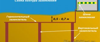
And finally, about what a ground loop is.
In short, these are several metal pins (under normal natural conditions - three), deeply immersed in the ground, connected by conductors to each other and the grounding bus in the building.
What is grounding?
Protective grounding is the intentional connection to ground of those parts of electrical equipment that, during normal operation of the electrical network, are not under the influence of voltage, but may come under its influence as a result of an insulation breakdown. The main purpose of grounding is to protect people from electric current.
The main component of protective grounding is the circuit. It is a design of natural or artificial grounding electrodes, that is, several grounding electrodes are connected into a single whole. Steel rods are most often used as electrodes. Copper rods are used less frequently due to the fact that they are expensive.
But if you have the financial means, keep in mind that copper is the ideal option and the best conductor.
Logically, it is clear that the ground loop should be located in the ground. Since we are interested in protecting the house, a suitable place with normal soil is selected not far from the building and power panel. Three pins are driven into the ground so that they are arranged in a triangle, and the distance between them is 1.5 m.
These electrodes must be driven in as deep as possible (their length must be at least 2 m).
Now you will need a welding machine and a metal bus, with the help of which the electrodes need to be tied together into an equilateral triangle. The circuit is ready, now you need to attach a copper conductor to it, which then goes into the shield and is connected there to the grounding busbar. And the grounding conductors from all sockets are output to this busbar.
Before use, it is necessary to check the circuit for grounding resistance.
The following video explains what grounding is:
Checking protective grounding parameters
In addition to the obvious components of the protective “earth” system: such as a contact block, wires going to electrical installations, connection to a circuit in the ground, the earth itself plays an important role in providing protection. Accordingly, you need to make sure of the following:
- Between all elements of the circuit (pins, connecting bars, conductor into the room to the terminal block) there is a reliable electrical connection with minimal resistance.
- The voltage applied to the circuit (in the event of an accident) spreads across the physical ground with maximum current. This is only possible with good contact between the metal and the ground.
- The physical conditions of the terrain (ground) can ensure reliable contact even under poor (in terms of electrical current) conditions. Namely, drying out of the soil, cracking of the earth in the places where ground electrodes are installed.
Of course, no one takes measurements of parameters on every element of the grounding system. This will be required only in case of non-compliance with the standards, to find the so-called “weak link”.
By what principle is the protective ground loop checked?
It is necessary to create a complete analogue of a circuit that is known to work, and compare the indicators with the tested object. For this purpose, there are complexes for testing working grounding.
Let’s make a reservation right away: it is possible to make such a kit yourself, but it is expensive and impractical. Likewise, checking the parameters of protective grounding using standard measuring instruments (multimeter) will not show a reliable picture. And the tester will not be able to generate the high voltage necessary to measure spreading parameters. Therefore, it is better to either rent equipment or invite a specialist.
You can buy a set like this, but it is unlikely to pay for itself in the foreseeable future. Even taking into account that the frequency of checking grounding devices is once a year (for both residential and industrial facilities), it is easier to get one-time access to the equipment.
Why conduct regular checks?
In order for the grounding of a private house to work properly, you need to periodically check the system. For industrial buildings, such inspections are regulated by certain standards and requirements. For a private home, it is necessary to carry out minimal control, which consists of periodic checks of the functionality of the grounding and the quality of connections of metal elements. It is enough to carry out regular checks at home using a multimeter, which determines the operation of the grounding.
According to the frequency of inspections, they are divided into:
- for acceptance;
- planned (operational);
- unscheduled.
Routine checks include a visual inspection of the system every 6 months and a check of the quality of metal connections once a year.
If the grounding is in order, then any malfunction of electrical appliances will not cause harm. Electric current will be discharged through the grounding system into current-carrying elements in the ground and then spread evenly into the depths of the soil.
The cause of a malfunction of the grounding system may be the process of corrosion of the metal of the current-carrying electrodes, since they are located in the ground - a favorable environment for the development of such processes. Due to this phenomenon, the resistance of the electrodes may increase and there is a danger of poor flow of electric current.
Also, as a result of corrosion, the electrodes become covered with individual rust flakes, which impair electrical contact. This may also cause an increase in the resistance of the grounding system.
As a result of such processes, the passage of current through the system deteriorates and the degree of grounding protection decreases. Therefore, checking the grounding system should begin with a visual inspection of all constituent elements. Once you are sure that the ground loop is in good technical condition, you can check the operation of the system with a multimeter.
If you are not confident in your knowledge or simply do not want to delve into all the intricacies of monitoring grounding resistance, you should call a specialist to carry out work related to electricity or contact an organization that performs such work.
Typical device connection diagram
The principle of simultaneous use of a voltmeter-ammeter on the test section of soil works. There are three quantities: resistance, voltage, current. The parameters are calculated according to Ohm's law. We know the initial voltage, and the device maintains the current. Knowing the voltage drop between the test rods, we can calculate the ground loop resistance with high accuracy.
There is an error, but it is insignificant in comparison with the measured values. The contact resistance of the test electrode with the ground is generally taken as zero, provided that the rod is clean and not covered with corrosion.
Most modern devices immediately provide ready-made parameters for protective grounding, but in older (but no less reliable and accurate) designs, you will need to perform a simple division operation. In accordance with Ohm's law.
Checking grounding with a megohmmeter follows the same principle, only the measurement error will be higher. Still, the earth is not a conductor of electricity in the usual sense.
Resistance factors
To test the compliance of the grounding device with the requirements of the standards, the resistance to current spreading Rз is measured. Ideally, this indicator should be zero. However, in reality this figure is unattainable.
The value (Rз) includes several components:
- The resistance of the material installed underground of the electrode, as well as the resistance at the contact of the metal with the conductor. However, this indicator is not so important due to the excellent conductivity of the materials used (copper-coated steel or pure copper). The indicator is ignored only in the case of a high-quality connection to the conductor.
- Resistance between soil and electrode. The indicator is ignored if the electrode is tightly installed and the contact is not painted or covered with a dielectric. However, over time, the metal rusts and its conductivity decreases. Therefore, copper-plated rods should be used or spreading resistance measurements should be taken. To reduce the intensity of corrosion, welding seams are varnished.
- Soil resistance. It is considered the most important factor. Particular importance is attached to nearby soil layers. As layers are removed, the resistance decreases. At a certain distance the resistance becomes zero.
- The heterogeneity of the electrical characteristics of the soil is difficult to take into account. Based on this, the actual Rз is measured. For a single simple grounding structure, the surface layers of the earth are of decisive importance, and for a contour structure, the deep layers are of decisive importance.
No tags for this post.
It is better to use a megohmmeter to assess other safety factors
For example, insulation resistance. We are not talking about direct danger. That is, if you grab a wire with your hand in which the dielectric properties of the insulation are normal, you will not receive an electric shock.
But there is an additional danger: insulation breakdown under load. This unpleasant fact leads to malfunctions and, what’s more scary, to electrical circuit fires.
A megohmmeter for measuring insulation resistance is a voltage generator and a precision instrument in one housing.
The classic version (still used successfully today) produces voltage up to 2500 volts. Don't be afraid, the currents during operation are negligible. But you only need to hold on to the insulated handles of the measuring cables.
The high voltage potential easily reveals flaws in the insulation, and the meter needle shows the true resistance. Before starting work, you should turn off all voltage-supplying circuit breakers and get rid of residual potential: ground the wire.
To measure the breakdown between wires in one cable, two wires are used. They are connected to the cores of the disconnected cable, and measurements are taken. If the resistance is below normal, the cable is rejected. No one knows when a potential breakdown site will cause trouble.
To measure earth leakage, one wire is connected to the protective ground (in the area where the cable under test is laid), and the second to the central core. The voltage for testing should be higher. If the wire cannot be connected to ground, the measurement is carried out by applying a second electrode to the outer surface of the insulation.
If there is a screen (cable armor), a three-wire measurement system is used. the third wire is connected to the shield of the cable being tested.
The general scheme is exactly this, but each model of the device has its own instructions. Modern megohmmeters with a digital display are even easier to understand than the old pointer meters.
Using a megohmmeter, you can also test motor windings. But this is a separate topic. Information for those who think that all these devices are narrow-profile: using a shunt system, you can turn a megaohmmeter into a precision ohmmeter or voltmeter.
profazu.ru
Working with a megohmmeter
During testing, the megohmmeter produces a very high voltage - 500 V, 1000 V, 2500 V. In this regard, measurements must be taken very carefully. At enterprises, persons with an electrical safety group of at least 3 are allowed to work with the device.
Before taking measurements with a megohmmeter, the circuits under test are disconnected from the power supply. If you are going to check the condition of the wiring in a house or apartment, you need to turn off the switches on the panel or unscrew the plugs. Then turn off all semiconductor devices.
One of the options for modern megaohmmeters
If you check the socket groups, remove the plugs of all devices that are included in them. If the lighting circuits are checked, the light bulbs are unscrewed. They will not withstand the test voltage. When checking the insulation of the motors, they are also completely disconnected from the power supply. After this, grounding is connected to the circuits being tested. To do this, a stranded wire in a sheath with a cross-section of at least 1.5 mm2 is attached to the “ground” bus. This is the so-called portable grounding. For safer operation, the free end with the exposed conductor is attached to a dry wooden holder. But the bare end of the wire must be accessible so that it can touch wires and cables.
Requirements for ensuring safe working conditions
Even if you want to measure the cable insulation resistance at home, before using a megohmmeter you should familiarize yourself with the safety requirements. There are several basic rules:
- Hold the probes only by the insulated part limited by stops.
- Before connecting the device, turn off the voltage and make sure that there are no people nearby (along the entire route being measured, if we are talking about cables).
How to use a megohmmeter: electrical safety rules
The rules are not very complicated, but your safety depends on their implementation.
How to connect probes
The device usually has three sockets for connecting probes. They are located at the top of the instruments and are labeled:
- E - screen;
- L-line;
- Z - earth;
There are also three probes, one of which has two tips on one side. It is used when it is necessary to exclude leakage currents and clings to the cable screen (if there is one). There is an “E” on the double tap of this probe. The plug that comes from this outlet and is installed in the corresponding socket. Its second plug is installed in the “L” socket - line. A single probe is always connected to the ground socket.
Probes for megaohmmeter
There are stops on the probes. When taking measurements, grasp them with your hands so that your fingers reach these stops. This is a prerequisite for safe operation (remember about high voltage).
If you only need to check the insulation resistance without a screen, place two single probes - one in the “Z” terminal, the other in the “L” terminal. Using crocodile clips at the ends, we connect the probes:
- To the wires being tested, if you need to check the breakdown between the wires in the cable.
- To the core and the “ground”, if we check the “breakdown to ground”.
There is a letter “E” - this end is inserted into a socket with the same letter
There are no other combinations. The insulation and its breakdown are checked more often; working with the screen is quite rare, since shielded cables themselves are rarely used in apartments and private houses. Actually, using a megohmmeter is not particularly difficult. It is only important not to forget about the presence of high voltage and the need to remove the residual charge after each measurement. This is done by touching the ground wire to the wire you just measured. For safety, this wire can be secured to a dry wooden holder.
Measurement process
We set the voltage that the megohmmeter will produce. It is not selected randomly, but from a table. There are megohmmeters that work with only one voltage, and there are those that work with several. The latter, of course, are more convenient, since they can be used to test various devices and circuits. The test voltage is switched using a knob or button on the front panel of the device.
| Item name | Megohmmeter voltage | Minimum permissible insulation resistance | Notes |
| Electrical products and devices with voltage up to 50 V | 100 V | Must correspond to the passport data, but not less than 0.5 MOhm | During measurements, semiconductor devices must be bypassed |
| too, but with voltage from 50 V to 100 V | 250 V | ||
| too, but with voltage from 100 V to 380 V | 500-1000 V | ||
| over 380 V, but not more than 1000 V | 1000-2500 V | ||
| Switchgears, switchboards, conductors | 1000-2500 V | Not less than 1 MOhm | Measure each section of the switchgear |
| Electrical wiring, including lighting network | 1000 V | Not less than 0.5 MOhm | In hazardous areas, measurements are carried out once a year, in others - once every 3 years |
| Stationary electric stoves | 1000 V | Not less than 1 MOhm | The measurement is carried out on a heated, disconnected stove at least once a year. |
Before using a megohmmeter, we make sure that there is no voltage on the line using a tester or an indicator screwdriver. Then, having prepared the device (set the voltage and set the measurement scale on the dials) and connected the probes, remove the grounding from the cable being tested (if you remember, it is connected before starting work).
The next stage is to turn on the megohmmeter: on the electronic ones we press the Test button, on the pointer ones we turn the dynamo handle. We turn the switches until the lamp on the body lights up - this means the necessary voltage has been created in the circuit. In digital, at some point the value on the screen stabilizes. The numbers on the screen indicate the insulation resistance. If it is not less than the norm (the averages are indicated in the table, and the exact ones are in the product data sheet), then everything is normal.
How to take measurements with a megohmmeter
After the measurement is completed, we stop turning the knob of the megohmmeter or press the end of measurement button on the electronic model. After this, you can disconnect the probe and remove the residual voltage.
In short, these are all the rules for using a megohmmeter. Let's look at some measurement options in more detail.