Grounding is one of the main factors providing protection against electric shock. In accordance with Chapter 1.7 of the PUE, all grounding systems for electrical installations can be divided into two groups: - systems with a solidly grounded neutral, these include the TN grounding system (NC, TN-CS, TN-S) and the TT grounding system; — systems with an isolated neutral, these include the IT grounding system;
The first letter of the abbreviation indicates the nature of the grounding of the power source, and the second - the nature of the grounding of the open conductive parts of the power receiver:
- T (from the French terre - earth) - grounded;
- N (from the French neutre - neutral) - connection to the neutral of the power source (grounding);
- I (from the French isolé - isolated) - isolated from grounding.
The article also contains the following abbreviations:
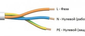
- N - functional (working) zero - neutral conductor used to connect an electrical receiver.
- PE - protective zero - a protective conductor designed for grounding electrical equipment housings.
- PEN is a conductor that combines the functions of zero protective and zero working conductors.
Now we will analyze in detail the listed types of grounding systems.
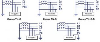
TN-C grounding system
The TN-C system is a TN system in which the neutral protective and neutral working conductors are combined in one conductor along its entire length. That is, with this system, a common PEN conductor is used, which is used both to connect electrical receivers and to ground their open conductive parts (cases).
TN-C grounding system diagram:
As can be seen in the diagram, with this system, the current-carrying housings of electrical equipment are grounded, this is necessary so that when a phase wire is shorted to the housing of the electrical receiver, due to its breakage or damage to the insulation, a short circuit occurs, which, in turn, would lead to the activation of protective equipment (circuit breaker) and power outage.
The main disadvantage of the TN-C system is the loss of its protective functions in the event of a burnout (break) of the PEN conductor, while a life-threatening electrical potential may arise on the grounded electrical equipment housing.
Due to the insufficient degree of protection, this system is not currently used, but it is still found in older buildings. When reconstructing old buildings, the TN-C grounding system is replaced with a TN-CS or TN-S system.
System designation, decoding
To designate each system, a letter index consisting of several letters is used.
The first letter in the index indicates the nature of the grounding of the main power source of the devices (transformer substation), and the second letter indicates the grounding of open sections of electrical installations.
For designation, certain letters of the Latin alphabet are used, each of which has its own decoding:
- T – grounded (from “Terre” – earth);
- N – neutralized, connected to the neutral of the source (from “Neuter” - neutral);
- I – isolated (from “Isole” – isolation).
These three letters are used to designate grounding systems that are included in the international standard.
Three grounding systems according to IEC are designated:
- TN (which in turn is divided into subsystems TN-C, TN-S, TN-CS);
- TT;
- IT.
Additionally, the classification introduced the letter designation of neutral conductors involved in grounding systems:
- N – worker;
- PE – protective;
- PEN – combined (combined), including both working and protective neutral conductors.
All of these systems have their own design features, which determine their scope of use.
For residential use, TN grounding subsystems are more suitable.
The TT system is applicable for mobile buildings (construction and other trailers, kiosks with metal surfaces), but IT is used mainly for organizing the grounding of laboratories.
The grounding system used for electrification of premises must be indicated in the design documentation, since in order to carry out maintenance and repair work it is necessary for the electrician to know exactly which system is used.
The existing standard for the grounding system is international, so we also use it.
Moreover, all the regulations in force in our country concerning grounding systems are fully spelled out in the rules for the construction of electrical installations (PUE). Moreover, the PUE operates both on the territory of the Russian Federation and Ukraine.
These rules are general provisions for the correct implementation of electrification, operation of electrical appliances and protection.
Next, we will consider the features of each of the systems, as well as their positive qualities and disadvantages.
Grounding system TN-CS
The TN-CS system is a TN system in which the functions of the neutral protective and neutral working conductors are combined in one conductor in some part of it, starting from the power source. In other words, with this system there is a PEN conductor which, in a certain part of this system, is divided into a zero working (N-conductor) and a zero protective (PE-conductor).
According to clause 1.7.135 of the PUE, at the point where the PEN conductor is divided into the neutral protective (PE) and neutral working (N) conductors, it is necessary to provide separate clamps or busbars for the conductors, connected to each other. The PEN conductor of the supply line must be connected to the terminal or bus of the neutral protective PE conductor.
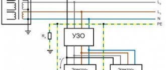
Thus, the TN-CS grounding system diagram will look like this:
Note: the jumper between the buses must have a cross-section no less than the cross-section of the PEN conductor.
This system is more reliable and provides a higher level of electrical safety than the TN-C system; in addition, the TN-CS system provides protection against zero loss, and its installation is slightly more expensive than the TN-C system.
However, this system also has a significant drawback - if the PEN conductor is damaged in the network section between the power source and the building, a life-threatening electrical potential will appear on all electrical equipment housings connected to the PE conductor.
To prevent such a development of events with the TN-CS system, the PEN conductor is re-grounded, as shown in the diagram.
Due to the low cost of the TN-CS system and its good protective characteristics, this system is currently widely used.
Peculiarities
With the TN-C system grounding type (see Figure 1), one of the live parts of the power source is grounded, usually the neutral of the transformer. All exposed conductive parts of Class I electrical equipment installed in a building's electrical installation have an electrical connection to the grounded neutral point of the transformer. To provide this connection, PEN conductors are typically used in both the low-voltage electrical distribution network and the building electrical installation. If the electrical distribution network includes an overhead power line (OHL), then its PEN conductor is usually grounded at several points, performing the so-called re-grounding of the PEN conductor.
The PEN conductor of the electrical distribution network “originates” from the corresponding protective grounding and neutral bus (PEN bus) of the low-voltage switchgear of the transformer substation and “ends” at the input terminal of the ASU of the electrical installation of the building. The PEN conductors of the building's electrical installation begin from this terminal, to which, as a rule, all exposed conductive parts of class I electrical equipment are connected. That is, the PEN conductor, performing the functions of a protective conductor, permeates the entire electrical distribution system from the power source to the exposed conductive parts of the building's electrical installation .
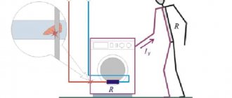
However, in some cases, exposed conductive parts of Class I electrical equipment may be connected not only to PEN conductors, but also to the protective PE conductors of the building's electrical installation. For example, when three-phase Class I electrical equipment is used in a building's electrical installation, which does not have a neutral and does not require neutral conductors for its normal operation (see Figure 2), protective conductors are connected to their exposed conductive parts.
If the electrical installation of the building connecting to the overhead line and the branch from the overhead line to the input is made with bare wires, then the PEN conductor of the electrical distribution network “ends” at the terminal connecting it with the PEN conductor of the input cable to the electrical installation of the building.
Grounding system TN-S
The TN-S system is a TN system in which the neutral protective and neutral working conductors are separated throughout its entire length.
Grounding system TN-S diagram:
This system provides a high level of security, because it eliminates the possibility of dangerous electrical potential arising on electrical equipment housings if the supply line is damaged.
However, the TN-S system has not become widespread due to its main drawback - high cost, which is due to the need to connect consumer electrical installations to the power source with five wires for a three-phase connection or three wires for a single-phase connection, while the domestic energy industry is focused on four-wire three-phase power supply circuits, this means that if you decide to connect via the TN-S system, connection to existing power supply networks will be impossible; for such a connection it will be necessary to conduct a separate five-wire line from the power source (transformer substation).
Execution examples
Rice. 2. TN-S single-phase two-wire system with separated grounded linear conductor and protective conductor throughout the system
Rice. 3. TN-S three-phase three-wire system with separated grounded linear conductor and protective conductor throughout the system
Fig 4. TN-S three-phase four-wire system
TT grounding system
A CT system is a system in which the neutral of the power source is solidly grounded, and the exposed conductive parts of the electrical installation are grounded using a grounding device that is electrically independent of the solidly grounded neutral of the source.
TT grounding system diagram:
In accordance with clause 1.7.59. PUE power supply of electrical installations via the TT system is allowed only in cases where electrical safety conditions in the TN system cannot be ensured . In addition, in such electrical installations there must be an automatic power shutdown with the mandatory use of an RCD. In this case, the following condition must be met:
Ra Ia ≤ 50 V
where Ia is the tripping current of the protective device; Ra is the total resistance of the grounding conductor and the grounding conductor, when using an RCD to protect several electrical receivers - the grounding conductor of the most distant electrical receiver.
Flaws
The “classical” TN-C system can only be implemented in those special-purpose low-voltage electrical installations that have a small number of class I power receivers connected to electrical circuits made of copper conductors with a cross-section of 10 mm2 or more or aluminum conductors with a cross-section of 16 mm2 or more. Since the share of such low-voltage electrical installations in the total number is negligible, and similar building electrical installations practically do not exist, the TN-C system grounding type can be considered as a “theoretical” system grounding type, usually used to explain the 4 “practical” system grounding types TN-S, TN-CS, TT and IT.
Ensuring an adequate level of electrical safety in electrical installations of buildings largely depends on the reliable functioning of protective conductors, namely on the guaranteed continuity of their electrical circuits. The continuity of the electrical circuit of the protective conductor can be maintained for as long as desired when a small electric current flows through it under normal conditions, the prolonged effect of which on the connecting contacts does not lead to a deterioration in their quality. Significant operating currents constantly flow through the PEN conductor, which, acting on the connecting contacts, can lead to deterioration in their quality and even loss of electrical continuity of the PEN conductor circuit.
When using the TN-C system grounding type in electrical installations of buildings, the same level of electrical safety cannot be ensured as when using the TN-CS and TN-S system grounding types. A greater level of electrical safety in the TN-CS and TN-S systems is, first of all, achieved due to the use of separate protective conductors in the electrical installations of buildings, through which leakage currents flow under normal conditions. Their values are significantly lower than the load currents that usually flow through PEN conductors. Minor electrical currents have less negative impact on electrical contacts in protective conductor circuits. Therefore, the probability of loss of continuity of the electrical circuit for the protective conductor is significantly less than for the PEN conductor.
Therefore, protective conductors, which have a higher degree of reliability than PEN conductors, should be used in electrical installations of buildings that are “operated” by ordinary people. For this reason, the prohibition imposed by clause 312.2.1 of GOST 30331.1-2013 on the use of the TN-C system type of grounding for electrical installations of residential and public buildings, retail establishments and medical institutions, in the electrical circuits of which the requirements of the national standard prohibit the use of PEN conductors, is quite justified. .
Therefore, it is logical to say that low voltage electrical installations that comply with the TN-C system earthing type must be operated by trained and qualified persons who have received special training to enable them to understand the risks and avoid the dangers created by electricity.
IT grounding system
IT system - a system in which the neutral of the power supply is isolated from earth or grounded through devices or devices having high resistance, and the exposed conductive parts of the electrical installation are grounded.
IT grounding system diagram:
The IT system is used, as a rule, in special-purpose electrical installations that are subject to increased safety requirements, for example laboratories, coal mines, and can also be used in hospitals for emergency power supply and lighting, etc.
Grounding systems in a private house: types, differences and design features
Much has already been said about how important a properly installed grounding system is for a private house or cottage. Therefore, there is no particular need to repeat about the danger of electric shock in a house that is not connected to a ground loop. And if you want to ensure the maximum safety of your living space, then the information presented in this article will no doubt be useful to you.
Types of grounding for a private house
Depending on the design features of the power line approaching the house, various grounding systems are used. The following types are distinguished: TN-S, TN-C, TN-CS, TT, etc. Private houses and cottages are usually connected to two types of grounding systems: TN-C-S and TT. And if there is no grounding in your house, then these systems are the easiest to implement in practice; it is them that many craftsmen create on their own, and it is they that will be discussed in this article.
Let us briefly explain what the letters in the names of the systems mean:
- The first character indicates the grounding parameters of the power supply (T - ground, etc.).
- The second symbol (N or T) characterizes the grounding parameters of open parts of household electrical installations. The letter N, for example, denotes grounding or connection of the protective conductor of a home electrical installation with the neutral of the power source (transformer substation).
- The letters S and C indicate a subtype of system in which grounding is carried out through the power source.
Simply put, if the first letters in the designation are TN, then we are talking about a system with a solid grounding of the power source, and the consumer’s electrical system is connected to its neutral through neutral and protective conductors. As we have already said, grounding systems come in several varieties:
- TN-C is a system that has combined neutral and protective conductors. The supply line in this case consists of two- or four-core cables (phase and neutral conductors - in a single-phase power supply system, three phase and one neutral - in a three-phase power supply system). The TN-C system can hardly be called a full-fledged grounding system, because the grounding conductors of the electrical installation in it are connected to the neutral wire coming from the transformer. It is usually called grounding, because it is hardly capable of performing all the functions of a grounding loop.
- TN-S is a system that has separated neutral and protective conductors. The supply line in this case consists of three- or five-core cables (phase, neutral and protective conductors - in a single-phase power supply system, three phase plus neutral and protective conductors - in a three-phase power supply system).
- TN-CS is a system in which the neutral and protective conductor combines their functions only in a certain area, which begins near the power source and ends at the entrance to the house. Here they are divided into neutral protective (PE) and neutral working (N) wires (the protective conductor in such a system is re-grounded). In essence, the TN-CS system is created on the basis of the TN-C.
- TT is a system in which the home power supply system has a separate solid grounding, which is not connected in any way to the grounding of the supply substation.
Grounding in all TN category systems is carried out through a transformer substation, while the TT system involves the creation of a grounding loop directly near the house. One can argue for a long time about which of the two systems is better – TN-CS or TT, so let’s immediately outline the pitfalls of these two systems.
If you are thinking about creating a TN-CS system, then first of all you should make sure of the reliability of the power line supplying electricity to your home. After all, the condition of suburban power lines (and they are, in most cases, overhead) leaves much to be desired. No one can guarantee that one fine day, as a result of an accident on the line (if a flimsy support tilts under its weight, etc.), the exposed neutral wire will not connect to the phase wire. As a result, the zero will burn off from the transformer, and we will get a deadly voltage “walking” through the body of household electrical appliances.
AlexeyL FORUMHOUSE user
For the TN-CS circuit, you must either be completely confident in the safety and reliability of the PEN conductor coming to you on the street, or you must guarantee this safety with your own grounding. Given the typical state of local air networks, the only certainty is the opposite: the unreliability of PEN. And the construction of a grounding system capable of withstanding the zero current of many neighbors in the event of a broken neutral and a large imbalance of loads across phases is a very difficult and expensive task.
Let us explain: PEN is a combined working neutral (N) and protective neutral (PE) conductor connecting the transformer substation with the incoming home panel.
The use of SIP cable as part of the supply line provides some safety guarantees, but if the condition of the ground supports is unsatisfactory, all these guarantees can be called into question. Simply put, it is possible to create a TN-CS type grounding system only if you have full confidence in the reliability of the supply power line.
The TT system in a private house also has its disadvantages. Systems of the presented type require the mandatory presence of residual current devices (RCDs) or circuit breakers in the grounding circuit, which should be regularly checked for operability. To ensure safe operation, the CT must be equipped with potential equalization systems and an artificial grounding loop, the creation of which requires time, effort and certain costs.
In practice, creating a TN-CS system always looks more preferable, but if the condition of the current supply lines is questionable (the supply line is formed by bare conductors, there are frequent breaks, air supports are in poor condition, etc.) it is recommended to create a system as a more reliable alternative TT.
Briefly about the TN-S system
If a TN-S system is connected to the house, then it is enough to equip the input panel with a grounding bus, to which the PE input grounding conductor and protective conductors going to household consumers should be connected. The PE conductor can be connected to a repeated grounding circuit. We will return to the question of how to do this later.
AlexPetrowFORUMHOUSE user
With TN-S, a five-wire line with separate PE and N comes to the consumer. In such a system, nothing needs to be divided.
We are talking about separating the incoming neutral wire, which is supplied to the consumer in TN-C systems and is divided when creating a TN-CS system. A similar division is shown in the diagram.
TN-CS system design
If a TN-C system is suitable for your home, if you have verified that the supply line is in impeccable condition and have made sure that a SIP cable is used as the supply conductor, you can begin to create a TN-CS type grounding system.
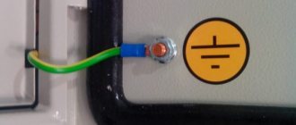
The conductor is divided into the protective wire PE (yellow-green) and the neutral wire (blue) in the input panel.
In the shield, re-grounding is connected to the system.
In accordance with the updated edition of the PUE rules, the separation of the PEN conductor must be performed before the input switching protective device and before the electric meter. It is strictly forbidden to include protective and switching devices in the circuit of PEN and PE conductors. You can only break the circuit of conductor N (PUE 1.7.145).
AlexPetrow
Conductors PEN and PE are inseparable! All devices with switching (circuit breakers, circuit breakers, batchers, metering devices, etc.) must be located on the line of conductor N (it can be “torn”, and sometimes necessary).
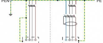
The PEN conductor is divided according to the following scheme:
For separation, two buses should be used: the main ground bus (GZSh) and the zero bus (N). The main grounding bus is connected to the additional grounding circuit through the panel body, the PEN input cable is connected to it and the grounding terminals of the sockets installed in the house are connected. The following are connected to the N bus: an electric meter, circuit breakers and power terminals of home energy consumption points.
The main grounding bus becomes the PE bus after the jumper connecting the GZSh and N. It is to the PE that an additional grounding circuit and protective conductors leading to the grounding terminals of the sockets are connected.
AlexPetrow
In fact, physically and organoleptically there should be two tires - PE (GZSh) and N. PEN is divided according to the “rule of the Russian letter N” - this is what the correct division looks like. The supply PEN can come to either end of the vertical line (bus), and this line after the jumper will always be PE. The other vertical line will always be N (along its entire length). A jumper is just a jumper. PE is grounded, and protective conductors will be switched on this bus, and N serves as a load current conductor. Once separated, they should not be combined.
The division is shown more clearly in the photo.
In accordance with the rules of the PUE, it is recommended that the main grounding bus be made of copper. The use of steel tires is allowed, but the installation of aluminum tires is strictly prohibited. GZSh and N tires are made from the same material.
stanislav-e88aFORUMHOUSE user
Zero (N) from the separating bus goes to the 2-pole input circuit breaker, then to the counter. From the meter zero to consumers. Double machines are not needed (except for the introductory one). PEN must be split before it. With the phase, everything is simple: it goes to the input machine, then to the meter, then to consumer groups.
The basic requirements for the PEN conductor separation unit are as follows:
- The zero separating bus N must be installed on an insulator, that is, it must be isolated from the panel body, to which the PE bus is additionally connected (after all, after separation, these two buses should not touch anywhere);
- All conductors suitable for dividing busbars must be secured using strong bolted connections, which ensures reliable connection and the ability to disconnect individual conductors;
- The cross-section of the main conductor must be greater than or equal to the cross-section of the PEN supply conductor.
It is recommended to use specialized wires as PE protective conductors. If the PE conductors and phase conductors are made of the same material, then the dependence of the minimum PE cross-section on the phase conductor cross-section will be as follows.
The “£” sign in this case means “≤”.
If the protective and supply conductors are made of different materials, then the PE cross-section must be equivalent in conductivity to the cross-section of the phase wires discussed in the table.
The minimum cross-section of the combined conductor in the TN-C system must correspond to the following values: 10 mm² for copper conductors and 16 mm² for aluminum. If the cross-section of the conductor is smaller, then it is prohibited to separate it! In this case, you should resort to creating a TT system.
Re-grounding and residual current devices in TN-CS systems
If you want to protect yourself and your family as much as possible from damage by leakage currents, then the TN-CS grounding system should be equipped with residual current devices (RCDs) or differential circuit breakers. In accordance with the recommendations of the updated edition of the PUE (Vol. 7), TN type systems equipped with residual current devices (RCDs) must be connected to re-grounding, which is mounted at the entrance to the house.
SB3FORUMHOUSE user
It is required to perform repeated grounding at the ends of overhead lines and branches from them with a length of more than 200 m, as well as at the inputs of overhead lines to electrical installations, in which protective automatic power off is performed as a protective measure against electric shock due to indirect contact.
If RCDs are not used in your system, and there is already re-grounding within 200 m of your panel, then there is no particular need to create additional grounding at the entrance to the house.
Crazy CatFORUMHOUSE user
If there is already re-grounding at a distance of 200 m from the input, or the input is made with a cable laid in the ground, there is no need for re-grounding.
About RCDs: for additional protection against leakage currents due to indirect contact with open surfaces of electrical appliances, it is recommended to introduce residual current devices (RCDs) or differential circuit breakers into the general power supply circuit. Such protection is triggered by weak leakage currents, turning off the power supply to the network (leakage currents, despite their small magnitude, can be dangerous to humans). Their installation is advisable for the reason that conventional circuit breakers operate only on short-circuit currents.
In modern systems, it is customary to install RCDs of two different ratings: a general fire-fighting RCD that triggers a leakage current of 100 mA, as well as one (or several) RCDs connected to a line of plug sockets and triggered by a current of 30 mA or 10 mA.
RCDs connected to household appliances that directly interact with water (washing machines, dishwashers, water heaters, etc.) must respond to a leakage current of 10 mA. RCDs are not installed on the line of lighting systems.
As a result, we will have a scheme like this.
The functionality of protection devices or differential circuit breakers must be checked regularly (once a month, etc.). For this purpose, there are special “test” buttons on the device body.
Re-grounding involves connecting the input panel housing to the ground loop.
In accordance with the rules of the PUE (clause 1.7.102), in alternating current networks with voltages up to 1 kV, underground structures of electrical supports, metal water pipes, grounding circuits of lightning rods, etc. can be used as a repeated grounding loop for TN-CS systems. should be used first. If this is not possible, then an artificial contour is created.
In DC networks, grounding conductors must be connected to an artificial grounding loop, which should not be connected to underground pipelines.
We will return to the issue of the design of an artificial grounding loop later.
The cross-section of the conductors connecting the shield and the grounding loop in networks with a solidly grounded neutral and with a voltage of up to 1 kV must correspond to the following parameters.
If an aluminum conductor is used, its area must be at least 16 mm².
Potential equalization system
After creating a grounding system equipped with automatic shutdown devices, a protective conductor appears in the house, connecting all elements of the power supply system. This conductor poses a potential threat. After all, if any consumer is damaged, a dangerous potential is transferred to the housing of all undamaged electrical appliances. It will be present there until the RCD is triggered, creating a danger upon direct contact. In order to reduce this voltage in a building, it is necessary to create a potential equalization system (PES) capable of equalizing the potential of all its conductive parts (building structures, utilities, etc.).
ASZyuzin1950FORUMHOUSE user
The potential equalization system is not an independent protection measure, but its presence is mandatory when using automatic power off.
The SUP is a kind of grid of conductors (PE) that connects all the current-carrying elements of the object through the GZSh, that is, through its PE part. The connection between the PE bus and the current-carrying parts of the building is made radially (a separate PE conductor is connected to each grounded structure). You can learn more about the design of the main (SUP) and additional (SUP) potential equalization systems in the corresponding section of FORUMHOUSE.
TT grounding system in a private house
If you have come to the conclusion that it is inappropriate or dangerous to connect a TN-CS system to your home, then the only alternative to ensure your own safety is to create a TT system. Its diagram looks like this.
As you can see, the main shield and grounding conductors are not connected anywhere to the input PEN conductor and the neutral wire - N.
The use of RCD protection devices or differential circuit breakers as part of the CT system is a prerequisite for its safe operation. The performance characteristics of the protective devices in this system correspond to the parameters of the RCD for TN-CS systems.
Also in TT systems a basic potential equalization system (EPS) must be created. Ideally, the OSUP is created in conjunction with an additional system (DSUP).
If the CT system is connected to a metal panel, then all conductors in the panel must be double insulated. As an alternative to metal shields, plastic shields can be used.
AlexPetrow
The metal shield is grounded. We make double insulation in the shield and take precautions against direct and indirect contact (the zero bus will be in an insulating box, etc.). If the shield is plastic, it’s even better (there are some for the street).
For more reliable insulation of conductors where they pass through the body of the metal shield, you can use special textolite bushings.
The GZSh is connected using a copper wire to a conductor leading to an artificial ground loop. In the panel, PE conductors coming from household consumers and from potential equalization systems are connected to the grounding bus.
It is advisable to make underground elements connecting the grounding loop to the shield from steel (from strip). The use of bare aluminum conductors is prohibited in this case.
Calculation and creation of a ground loop
As is known, the dangerous potential that arises in the PE protective conductor during a breakdown of phase voltage on the housing of a household device is directed to the area with the lowest resistance. And in order for the voltage to continue to flow into the ground when a person touches open parts of the electrical installation, protecting people from electric shock, the grounding loop must have low resistance. Therefore, the calculation of the grounding loop comes down to determining the resistance to current flow on the grounding device. This indicator depends on several factors:
- From the area of grounding elements.
- From the distance between them.
- From the depth of their immersion into the ground.
- From soil conductivity.
For CT grounding systems installed in networks with voltages up to 1 kV and equipped with RCD protective devices, the PUE rules (clause 1.7.59) establish the following relationship: RaIa <50 V. Where:
- Ia – minimum current setting of the RCD (in our case it is equal to 10 or 30 mA);
- Ra is the total resistance of all elements of the grounding system.
In accordance with the formula, for an RCD with a setting of 30A, this figure should not exceed - 1660 Ohms (the minimum requirement for a TT system). Such values, regulated by the rules of the PUE, can be misleading. Therefore, in practice, many people strive to achieve a ground loop resistance of no more than 4 ohms (which corresponds to the requirements for the power supply ground loop).
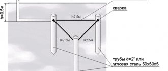
In order to meet the minimum condition for the resistance of the grounding loop, it is enough to drive one metal corner or pin 2...2.5 m long into the ground. In practice, in order to provide more reliable protection, several protective rods are used at once (most often – 3) specified length.
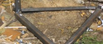
Bonus FORUMHOUSE User
At a distance of 90 cm from the strip foundation and parallel to it, three ground electrodes were hammered with a sledgehammer. Depth – 2.8 m, distance between them – 3.5 m.
Here is an example of successful protection consisting of a single ground rod.
person FORUMHOUSE user
I was able to drive 6 1.5 m electrodes into one point, but I was helped by Makita, who was taken from work for this task. Driven 0.2 m below zero level. I did not measure the grounding resistance, but the practice of using such electrodes as grounding conductors shows that an electrode 9–10 m long gives less than 4 ohms on our soils.
If you doubt the number and length of electrodes, then it is best to contact specialists to calculate the grounding loop. You can also find out these parameters from neighbors who have an existing grounding loop, approved by supervisory authorities for operation after carrying out appropriate resistance measurements.
The minimum cross-sectional dimensions of vertical electrodes can be taken from the table already familiar to us.
In practice, smooth steel rods with a diameter of at least 16 mm or pointed corners (50x50) are most often used as electrodes. To tie the electrodes, a steel strip measuring 4x40 or 5x40 is used.
BORIS LOKFORMHOUSE user
I carried out the grounding by hammering three 3-meter fittings (d16mm). The soil is wet, tightly plastic clay. Then, using welding, I connected the grounding conductors with a 4x40 mm steel bus.
The electrodes can be placed either in a row or at the corners of geometric shapes (at the corners of a triangle, etc.). In each specific case, their location is determined by the convenience of installation work and the availability of free space.
The distance between the electrodes is determined by the rod utilization factor, which is equal to – 2.2. That is, in order for the system to work with maximum efficiency, the distance between two identical electrodes must be no less than 2.2 times the length of each of them (in all directions). As this distance decreases (and in practice this most often happens), the efficiency of the system will decrease.
Before starting installation work, the top layer of soil is removed, and then, at the marked points, the electrodes are clogged.
The upper ends of the electrodes are tied with a strip or steel rod and connected by welding.
At the final stage, the grounding loop is connected to the electrical panel.
All connections in the ground loop structure must be made by welding.
For those who want to learn more about practical developments in the field of building home grounding systems, there is a topic on our portal dedicated to this issue. You can learn how to install a grounding system and what materials should be used based on the practical experience of FORUMHOUSE users. The video shows how to properly create a power supply system and other utilities in a country frame house.