Conventional image of automata
Drawings are developed in accordance with GOST 2.702-2011, which contains information on the rules for executing electrical circuits. GOST 2.709-89 (wires and contacts), GOST 2.721-74 (UGO in circuits for general use), GOST 2.755-87 (UGO in switching devices and contacts) are used as additional regulatory documentation.
According to state standards, a circuit breaker (protective device) in a single-line diagram of an electrical panel is represented by the following combination:
- straight line of electrical circuit;
- line break;
- side branch;
- continuation of the chain line;
- on the branch - an open rectangle;
- after the break - a cross.
Designations of circuit breakers on the diagram
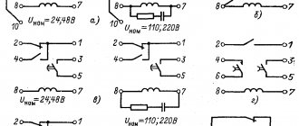
The machine for engine protection has a different symbol. In addition to the graphic, the diagram contains a letter image. Depending on the features of the machine, the electrical device has several recording options:
- QF is a circuit breaker for power circuits consisting of elements whose functional purpose is the production, transmission, distribution, and conversion of electricity.
- SF is a circuit breaker for an electrical control circuit, the purpose of which is to protect power circuits and control the operation of machines and equipment.
- QFD - difavtomat, an automatic circuit breaker with differential protection, often used to ensure increased safety during constant operation of electrical appliances, combines the functions of an RCD and a circuit breaker.
When developing an electrical circuit diagram, the degree of probable load of devices and equipment on the line is taken into account, and depending on the power of the devices, one switch or several circuit breakers can be installed.
Automatic switches.
Visio stencil Automatic switch.
The Visio stencil Automatic switch includes three options for symbols of automatic switches:
Symbols of circuit breakers (option 1).
Basic symbols (option 1):
Transformation of symbols is possible through the context menu of the figure by turning on/off the following functional symbols and their combinations:
- Switch function
- Disconnect function
- Automatic shutdown
- Manual drive
- it is possible to disconnect the mechanical communication line
- for two-pole, three-pole and four-pole switches there is a switch for each respectively: 2P ↔ 1P+N, 3P ↔ 2P+N, 4P ↔ 3P+N
Context menu for the symbol of the automatic switch.
Some of the possible options for transforming the symbol of a three-pole switch:
Similarly, you can get different configurations of symbols for other switches of this option.
Any of the symbols of the symbol can be positioned vertically or horizontally, as well as the moving and fixed contacts can be swapped.
Symbols of circuit breakers (option 2).
Basic symbols (option 2):
Transformation of symbols is possible through the context menu of the figure by turning on/off the following functional symbols and their combinations:
- switch function
- for two-pole, three-pole and four-pole switches there is a switch for each respectively: 2P ↔ 1P+N, 3P ↔ 2P+N, 4P ↔ 3P+N
- release function switch: electromagnetic;
- thermal;
- thermal + electromagnetic;
- residual current (RCD).
Context menu of the machine symbol symbol.
Some of the possible options for transforming the figure of a three-pole switch (option 2):
Options for the symbol of a three-pole machine
Similarly, you can get different configurations of symbols for other switches of this option.
Any of the symbols of the symbol can be positioned vertically or horizontally, as well as the moving and fixed contacts can be swapped.
Symbols of circuit breakers (option 3).
Selective connection of protective equipment
If a high load on the network is expected, the method of connecting several protection devices in series is used. For example, for a chain of four circuit breakers with a rated current of 10 A and one input device in the diagram, each circuit breaker with differential protection is graphically designated in series one after another with the device output to a common input device. What does this give in practice:
- compliance with the connection selectivity method;
- disconnecting only the emergency section of the circuit from the network;
- non-emergency lines continue to operate.
Thus, only one of the four devices is de-energized - the one that experienced a voltage overload or a short circuit. An important condition for selective operation: that the rated current of the consumer (lamp, household appliance, electrical device, equipment) be less than the rated current of the machine on the supply side. Thanks to the serial connection of protective equipment, it is possible to avoid fires in the wiring, complete blackout of the power system and melting of the wires.
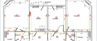
Representation of electrical equipment on plans
According to GOST 21.210-2014, a document regulating conventional graphic images of electrical equipment and wiring on plans, there are clear symbols for each type of electrical devices and the links connecting them: wiring, buses, cables. They are distributed for each type of equipment and unambiguously define it on the diagram in the form of a graphic or alphanumeric symbol.
The document provides views for:
- Electrical equipment, electrical devices and electrical receivers;
- Wiring lines and conductors;
- Tires and busbars;
- Boxes, cabinets, panels and remote controls;
- Switches, switches;
- Plug sockets;
- Lamps and spotlights.
Electrical equipment, electrical devices and electrical receivers
The category of electrical equipment includes: power transformers, oil switches, disconnectors and separators, short circuiters, grounding switches, automatic high-speed switches and concrete reactors.
UGO table for electrical equipment
Electrical devices and receivers include: simple electrical devices, general electrical devices with motors, electrical devices operating on an electric drive, devices with generators, devices that are motors and generators, transformer devices, capacitor and complete units, storage equipment, electric heating elements. Their designations are shown in the picture below.
UGO for electrical devices
Wiring and conductor lines
This category includes: wiring lines, control circuits, voltage lines, grounding lines, wires and cables, as well as their possible types of wiring (in a tray, under the baseboard, vertical, in a box, etc.). The tables below provide the main designations for this category.
The first table of designations for wiring lines
Wiring lines are cables and wires capable of transmitting electricity over fairly long distances. Electrical devices that are capable of transmitting electricity over a short distance are most often called conductors. For example, from a current generator to a transformer and so on.
Second table of designations for wiring lines
Third table of designations for wiring lines
Fourth table of designations for wiring lines
Tires and busbars
Busbars are cable devices that consist of conductor elements, insulation and distributors that transmit and distribute electricity in industrial premises. The symbols of tires and busbars are presented in the picture below.
Designation of tires and busbars
Boxes, cabinets, panels and remote controls
Among the boxes we can distinguish branch, inlet, broach, clamp. There are laboratory switchboards, regular and emergency lighting, and automatic switches. All these elements are needed to distribute electricity between individual sections of the circuit and devices. The designation conditions for these elements are presented in the picture.
UGO panels and control panels
Switches, switches and sockets
This includes plug sockets.
First table of symbols for switches
All these elements are used to switch, turn on and off electrical circuits.
Second table of symbols for switches
This could be lighting or voltage changes. The following tables contain basic designations for this type of electrical elements.
Third table of symbols for switches
Lamps and spotlights
Many circuits contain lamps, spotlights and other lighting elements. They are needed not only to signal certain circuit states, but also to illuminate some cases.
UGO lamps
Monitoring and control devices
Such devices include meters, programmed devices, measuring instruments, pressure gauges, temperature controllers and time relays. Their main element is sensors sensitive to certain factors.
Symbols of control devices
They have the following designations.
Symbols of control devices continued
The article cannot contain the graphic and alphanumeric designations of all electrical devices and elements, but the most commonly used ones were discussed in detail. GOST documentation of schematic graphic designations of electrical elements on circuits of various types and types, as well as their decoding, was also described.
Classification of devices
According to the drawn up diagram, electrical devices are selected. They must meet the technical requirements for a specific type of product. According to GOST R 50030.2-99, all automatic protective equipment is classified into several types according to the type of design, environment of use and maintenance. In this case, the unified standard refers to the use of GOST R 50030.2-99 in conjunction with IEC 60947-1. GOST is applicable for switching circuits with voltages up to 1000 V AC and 1500 V DC. Circuit breakers are classified into the following types:
- with built-in fuses;
- current-limiting;
- stationary, plug-in and retractable versions;
- air, vacuum, gas;
- in a plastic case, in a shell, open design;
- emergency switch;
- with locking;
- with current releases;
- serviced and unattended;
- with dependent and independent manual control;
- with dependent and independent control from the power source;
- switch with energy storage.
In addition, machines differ in the number of poles, type of current, number of phases and rated frequency. When choosing a specific type of electrical device, it is necessary to study the characteristics of the machine and check the compliance of the device with the electrical circuit diagram.
Marking on the device
Technical documentation obliges manufacturers of automatic devices to indicate full product markings on the housing. Basic symbols that must be present on the machine:
- brand – device manufacturer;
- name and series of the device;
- rated voltage and frequency;
- rated current value;
- rated differential current;
- UGO circuit breaker;
- rated differential short circuit current;
- contact marking designation;
- Operating temperature range;
- on/off position marking;
- the need for monthly testing;
- graphic designation of the RCD type.
The information indicated on the machine allows you to figure out whether the electrical device is suitable for the specific circuit indicated in the diagram. Based on the markings, drawings and calculation of power consumption, you can correctly organize the connection of the object to the power supply.
What do the inscriptions on the switch mean?
Symbols, numbers, letters, diagrams are applied to technical plastic with special indelible paint. Even with older models they remain readable. It is assumed that the user or electrician, barely glancing at the machine, should quickly determine its current characteristics and voltage.
Manufacturer and model of the machine
The top line of the marking block is occupied by the brand name. A certain color is selected for printing, often bright, and sometimes even by the shade you can determine which manufacturer’s products are in front of you.
Experienced electricians suggest not to skimp when buying machines and to purchase devices only from proven European brands: Schrack Technik , Schneider Electric , ABB , Schaltbau , Moeller , HAGER , Legrand . There are several Russian brands that you can also safely trust: Elektrotechnik , TDM ELECTRIC , EKF .
The line below indicates the device model. All other inscriptions, except for the manufacturer's name, are usually printed in gray, so the series can be easily confused with technical specifications.
In order not to be mistaken, we look exactly at the second line. The line or model designation may look like this: BA63 , SH200 , Acti9 .
You can try to decipher the series, but the technical characteristics are not always hidden behind the letters and numbers; more often it is just the name of a specific model.
The line designation can be printed either on a general gray background or on a colored line, which is located directly under the brand.
Determination of time-current characteristic
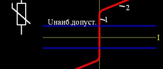
The next line is a combination of a Latin letter and a number. The first letter indicates the time-current characteristic. It refers to how quickly a switch operates when a certain amount of current flows through it. There are five different types in total: “B”, “C”, “D”, “K”, “Z”, but in everyday life machines B, C, D are used.
The dependence of quantities is often presented in the form of graphs that can be found on the Internet. They look like this:
Thus, if the value of k is between 3 and 5 - this is category B, between 5 and 10 - C, between 10 and 20 - D.
If you take two switches with the same rated current value, but with different tripping properties, they will also react differently. For comparison, consider C16 and B16. If we use the formula, then as a result we will get for C16 - 80-160 A, and for B16 - 46-80 A.
What does this look like in practice? Suppose the current sharply increases to 100 A. B16 will turn off instantly, since 80 A is enough for it, and for C16 to work, it takes some time for the plate to heat up. Then the thermal protection begins to operate and the machine turns off. The time difference usually takes a fraction of a second.
Symbol for ouzo in the diagram
No person, no matter how talented and savvy he may be, can learn to understand electrical drawings without first becoming familiar with the symbols that are used in electrical installation at almost every step. Experienced specialists claim that only an electrician who has thoroughly studied and mastered all the generally accepted designations used in project documentation can have a chance to become a true professional in their field.
Greetings to all friends on the website “Electrician in the House”. Today I would like to pay attention to one of the initial issues that all electricians face before installation - this is the design documentation of the facility.
Some compose it themselves, while others are provided by the customer. Among the multitude of this documentation, you can find copies in which there are differences between the symbols of certain elements. For example, in different projects the same switching device can be graphically displayed differently. Has this ever happened?
It is clear that it is impossible to discuss the designation of all elements within one article, so the topic of this lesson will be narrowed, and today we will discuss and consider how the designation of ouzo is carried out on the diagram .
Every novice master must carefully familiarize himself with generally accepted GOSTs and the rules for marking electrical elements and equipment on plan diagrams and drawings. Many users may disagree with me, arguing that why do I need to know GOST, I’m just installing sockets and switches in apartments. Design engineers and university professors should know the schemes.
I assure you this is not so. Any self-respecting specialist must not only understand and be able to read electrical diagrams, but also must know how various communication devices, protective devices, metering devices, sockets and switches are graphically displayed on the diagrams. In general, actively use project documentation in your daily work.
What types of electrical circuits might be useful?
Let's consider the design information from the point of view of an amateur electrician who wants to change the wiring in the house with his own hands or draw up a drawing for connecting the dacha to electrical communications.
First you need to understand what knowledge will be useful and what will not be needed. The first step is to become familiar with the types of electrical circuits.
All information about the types of circuits is presented in the new edition of GOST 2.702-2011, which is called “ESKD. Rules for the execution of electrical circuits."
This is a duplicate of an earlier document - GOST 2.701-2008, which talks in detail about the classification of circuits. There are 10 types in total, but in practice only one may be required - electric.
In addition to the type classification, there is also a standard one, which divides all drawing documents into structural, general, etc., with a total of 8 points.
The home craftsman will be interested in 3 types of diagrams: functional, schematic, installation.
Type #1 – functional diagram
The functional diagram does not contain details; it indicates the main blocks and assemblies. It gives a general idea of how the system works. For the electrical supply of a private home, it does not always make sense to draw up such drawings, since they are usually standard.
But when describing a complex electronic device or for equipping a workshop, studio or control room with electrical equipment, they can be useful.
Type #2 – circuit diagram
A schematic diagram, in contrast to a functional one, is a set of symbols, without knowledge of which it is difficult to understand the structure of the network as a whole. The drawing indicates all devices and connections between them. If the circuit is complex, containing, for example, redundant circuits, then operators use operational circuits that give an idea of “the current situation of switching devices.”
If you need to reflect only power lines, it is enough to draw a linear diagram, but to depict all types of circuits with monitoring and control devices you will need a complete one.
Type #3 – wiring diagram
A wiring diagram is a document that is convenient to use when installing networks. Using it you can find out which devices should be connected, where exactly and how far from each other they are located.
Uzo designation on a single-line diagram
The main groups of RCD designations (graphic and alphabetic) are used very often by electricians. The work of drawing up work diagrams, schedules and plans requires very great care and accuracy, since a single inaccurate indication or mark can lead to a serious error in further work and cause the failure of expensive equipment.
In addition, incorrect data can mislead third-party specialists hired for electrical installations and cause difficulties when installing electrical communications.
Currently, any ouzo designation on a diagram can be represented in two ways: graphic and alphabetic.
Which regulatory documents should be referred to?
Of the main documents for electrical diagrams that refer to the graphic and letter designation of switching devices, the following can be distinguished:
- – GOST 2.755-87 ESKD “Conventional graphic designations in electrical circuits of devices, switching and contact connections”;
- – GOST 2.710-81 ESKD “Alphanumeric designations in electrical circuits.”
Graphic designation of RCD on the diagram
So, above I presented the main documents according to which symbols in electrical circuits are regulated. What do these GOST standards give us for studying our question? I'm ashamed to admit, but absolutely nothing. The fact is that today these documents do not contain information on how the ouzo designation should be carried out on a single-line diagram.
The current GOST does not put forward any special requirements for the rules for drawing up and using graphic symbols for RCDs. That is why some electricians prefer to use their own sets of values and labels to mark certain components and devices, each of which may differ slightly from the values we are familiar with.
As an example, let's look at what designations are printed on the body of the devices themselves. Hager residual current device:
Or for example an RCD from Schneider Electric:
To avoid confusion, I suggest that you jointly develop a universal version of RCD designations that can be used as a guide in almost any working situation.
Letter designation of ouzo on electrical diagrams
Any element on electrical circuits is assigned not only a graphic designation, but also an alphabetic designation indicating a position number. This standard is regulated by GOST 2.710-81 “Alphanumeric designations in electrical circuits” and is mandatory for application to all elements in electrical circuits.
So, for example, according to GOST 2.710-81, it is customary to designate circuit breakers using a special alphanumeric designation in this way: QF1, QF2, QF3, etc. Switches (disconnectors) are designated as QS1, QS2, QS3, etc. Fuses in the diagrams are designated as FU with the corresponding serial number.
Similarly, as with graphic symbols, GOST 2.710-81 does not contain specific data on how to carry out the alphanumeric designation of RCDs and differential circuit breakers on diagrams .
What to do in this case? In this case, many masters use two notation options.
The first option is to use the most convenient alphanumeric designation Q1 (for RCD) and QF1 (for RCBO), which indicate the functions of the switches and indicate the serial number of the device located in the circuit.
That is, the encoding of the letter Q means “switch or switch in power circuits,” which may well be applicable to the designation of an RCD.
The code combination QF stands for Q – “switch or switch in power circuits”, F – “protective”, which may well be applicable not only to conventional machines, but also to differential machines.
The second option is to use the alphanumeric combination Q1D for the RCD and the combination QF1D for the differential circuit breaker. According to Appendix 2 of Table 1 of GOST 2.710, the functional meaning of the letter D means “differentiating”.
I very often saw in real diagrams the following designation: QD1 - for residual current devices, QFD1 - for differential circuit breakers.
What conclusions can be drawn from the above?
| Due to the fact that there is no designation for RCDs and differential circuit breakers according to GOST, the information discussed in this article does not apply to mandatory regulatory documents, but is only a RECOMMENDATION. Each designer can depict these elements on the diagrams at his own discretion. To do this, you just need to provide conventional graphic designations (UGO) of the elements, their decoding and explanations for the diagram. All these actions are provided for in GOST 2.702-2011. |
Graphic images in electrical circuits
An electrical network drawing is a set of graphic elements that together form an inextricable system. In practice, this is a set of devices connected by wires.
Most of the symbols are graphic. Letters and numbers are used to symbolically designate individual elements, their denominations and distances between objects.
Main base images
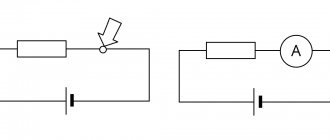
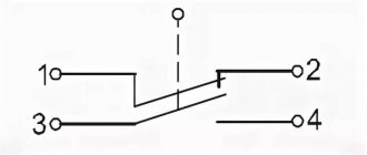
Electrical circuits lead to devices and installations that are equipped with contacts that can break or connect these circuits.
The simplest example is an ordinary switch. All contacts are divided into make, break and switch contacts - these are the ones that are displayed in the diagrams.
The listed graphic images are mandatory when drawing up circuit diagrams and are usually understandable even to a novice electrician.
Single Line Diagram Symbolism
Drawings are also used to assemble electrical panels. They are usually a single line diagram indicating RCDs, circuit breakers, contactors and other protective equipment.
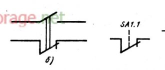
Some graphic symbols are similar to each other, so special attention is required when drawing up a diagram. For example, a contactor and a switch are designated the same, the difference is in a small element on the fixed contact.
Relay coils are designated by special symbols - in all images a rectangle is used as a basis.
To remember icons, associations or alphabetic clues are often used. For example, a motor drive is represented by a circle with the letter “M” inside it.
When drawing up a diagram, it should be borne in mind that quantity is also important for designating some symbols.
For example, if you need to indicate a 4-pin terminal block, then you should draw four crossed out circles in a row, and not one. Paired checkmarks when depicting sockets indicate the number of wires.
How are tires and wires depicted?
Linear graphics are used to designate buses, cables and wires - almost all symbols consist of straight lines.
Conductor connections are indicated by dots. If there is no mark at the junction of two lines, then this is a simple intersection.
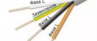
Wires vary in type, purpose, load, and installation method. All this can also be shown schematically.
Additional characteristics facilitate the selection of materials and installation of the electrical network. In the future, thanks to the characteristics indicated in the diagram, one can judge the potential capabilities of the already installed electrical system.
Sockets and switches on diagrams
The designation of switches is divided into several groups - according to the degree of protection, installation method (hidden or open). There are separate switches for two directions. 2- and 3-gang switches are designated differently.
Some light source control devices do not have symbols - for example, push-button devices and dimmers.
Nowadays, to save energy in large rooms, pass-through switches are often installed, which are controlled from 2 or 3 points. You can also find corresponding icons for them.
Sockets, like switches, are divided into groups according to the degree of protection. Within groups, devices are divided by the number of poles and the presence of protection. To designate blocks, alphanumeric signatures are used, indicating the number and purpose of installations in one block.
When memorizing the designations of various electrical elements on the diagrams, each conventionally depicted device should be correlated with a real product.
For example, popular types of sockets look like this:
In reality, electrical installation devices look like this:
Source: sovet-ingenera.com