When using electrical appliances, there is always a risk of electric shock. This probability comes from the properties of an ordered flow of charged particles: it passes through that section of the circuit in which the resistance has a minimum value. At various times, manufacturers of devices and components tried to combat this and protect people from the harmful or even fatal effects of current. But in the end, grounding remains the simplest and most reliable.
Grounding is used in industrial enterprises and country houses. It plays a special role in the case when the power of the device exceeds critical values. A person only needs to receive a blow with a force of 0.1 ampere to be guaranteed to die. Also, do not forget that even working equipment can be a source of danger. This can happen due to lightning and some other reasons. Therefore, the issue of installing grounding should be approached responsibly and take into account all the nuances.
Grounding tests
There is a lot of controversy regarding the installation of grounding and the norms for the flow of current through it. But experts agree absolutely unanimously on one thing - a specialist should check the quality of the installed circuit. This procedure will allow you to be confident in the correct installation of grounding in the house and will protect yourself and your loved ones from the dangerous effects of electric current. Tests are carried out both in enterprises where high-power generators and engines often operate, and in private homes - measuring ground resistance is done in the same way.
There are two main types of tests: acceptance and operational. The first ones are carried out in cases where the installation (or section of the network) is already completely installed and ready for immediate use. Before measuring the grounding resistance, it is determined whether the circuit is ready to absorb currents if necessary and whether its parameters meet the stated requirements. Among other things, it is necessary to regularly monitor that the installed grounding does not lose its properties over time. To do this, operational tests are carried out - a specialist checks a finished section of the network that is already in use. To carry out such a procedure, you need to free the network from consumers, so the whole process requires a little preparation.
Methods for measuring parameters of grounding devices
There are several known methods, using which it is possible to check the presence and measure the resistance of the ground electrode with fairly high accuracy. Let's look at each of these approaches in more detail.
Application of a multimeter
The question of how to measure ground resistance with a multimeter is not entirely correct. This can only be done with professional measuring equipment.
The procedure for measuring ground resistance with a multimeter usually comes down to a simple check of the connection of the ground contact of the socket to the protective circuit. How this can be checked using a tester and an iron, for example, has already been discussed in the corresponding article. Thus, when considering the issue of measuring grounding with a multimeter, this procedure is understood as checking its presence. In addition, this device can be useful for identifying hidden breaks in circuits or lost contacts.
Ammeter-voltmeter method
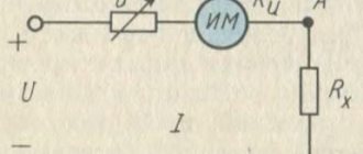
When applying this method of checking grounding resistance, you will need to assemble a chain, one of the components of which will be the grounding device being tested. It additionally includes a special current electrode, called “auxiliary”.
In addition, this circuit provides another one - a potential electrode (probe), designed to take readings of the voltage drop. It must be installed at approximately equal distances from both the current electrode and the grounded point. Due to this location, it is in an area with almost zero potential (photo below).
Ammeter-voltmeter method for measuring ground resistance
According to this scheme, measurements of grounding resistance are reduced to taking readings of voltage and current and to the subsequent calculation of the desired value according to Ohm’s law R=U/I . This testing method is optimally suited for country and private homes. To obtain the required current in the measuring circuit, you can use any transformer device suitable for power. As an option, some models of welding units are suitable.
Use of specialized devices
As already noted, it is not possible to measure grounding resistance with a simple tester (it is not capable of actually showing how many Ohms the grounding resistance is). This also applies to the circuit with a probe and a current electrode discussed above. To work with them, special analog devices of the following types must be used:
- F4103-M1
- Satellite-2016
- M-416 (multifunction meter)
- IS-10 (microprocessor meter)
- IS-20/1 (more advanced device)
- MRU-101 (professional device
For example, you can see how grounding resistance is measured using the M-416 device. When working with it, you must proceed according to the following plan:
- First, you should make sure that there are batteries in the device compartment (3 pieces of 1.5 Volts each, giving a total supply voltage of 4.5 Volts).
- Then the device prepared for use must be positioned strictly horizontally and calibrated.
- To do this, set the handle with the pointer to the “control” position and, holding the red button firmly pressed, set the pointer to “zero”.
Measurements of protective grounding resistance with this device are carried out according to the same scheme with two electrodes.
Connection diagram for the M-416 device
After the stakes are driven into the ground, wires are connected to them according to the diagram shown (device contacts 1, 2, 3 and 4). Then the indicator of the instrument switch “Range” is set to “x1” (photo below).
Installing the handle of the M-416 device in position x1
Then you should press the control button and turn the “Reochord” knob until the arrow on the indicator shows “zero”. The number indicated on the slider scale must be multiplied by the selected range, which will result in the measured value.
Please note: In a situation where the meter reading exceeds 10 ohms, the multiplier switch (range) should be set to a higher value: “X5”, “X20” or “X100”, and then repeat all the previously described operations. The amount of resistance in this case is determined by multiplying the Reochord reading by a new scale.
To carry out measurements using this method, more “advanced” digital instruments can be used, which are characterized by ease of measurement and maximum accuracy. With their help, you can not only take readings, but also save measurement data in the internal memory.
When carrying out checks using a megohmmeter, you must act according to the instructions (it is similar to the procedures described above for the M-416). However, before checking the grounding resistance with a megohmmeter, you should know that the error in taking readings in this case will be much higher. This fact is explained by the noticeable difference between the systems under study and the usual insulation resistance. This device is more suitable for checking the insulation resistance of electrical networks of grounded equipment, the reliability of which also affects the safety of its operation.
If the insulation is broken, an unpleasant effect can be observed, which is explained by the fact that the resistance of the human body is large enough for a dangerous potential to appear on it. If you accidentally touch a bare conductor, a current will flow through your body, the magnitude of which is sufficient to cause serious injury.
Current clamp measurement
The peculiarity of the method of measuring ground resistance using standard clamp meters is as follows:
- In this case, there is no need to disconnect the grounding device from the equipment being serviced.
- Auxiliary electrodes are also not needed in this situation.
- It becomes possible to quickly control the entire process of taking readings.
The principle of measuring with current clamps is as follows: the test current flowing through the grounding conductor or bus (which in this case is the secondary winding) is assessed by the current clamps by its magnitude. After this, a reading of the voltage acting in the circuit is taken using a voltmeter.
To calculate the desired resistance, you will need to divide the resulting voltage value in volts by the current value in amperes measured using clamps.
How is grounding measured?
To measure this value, an ohmmeter is used - a device that changes resistance. In this case, devices for determining grounding resistance must have certain characteristics. The most important thing: very low input conductivity. The measurement range of such devices is extremely small: usually it ranges from 1 to 1000 Ohms. The measurement accuracy in analog instruments does not exceed 0.5–1 Ohm, and in digital instruments - up to 0.1 Ohm.
Despite the widespread spread of Chinese and European devices, the most popular remains the M416, developed in the USSR. The device has four measurement ranges: from 0 to 10 Ohms, from 0.5 to 50, from 2 to 200 and from 100 to 1000. The device runs on three AA batteries. Despite this, it is difficult to call it mobile - the dimensions of the case are not very comfortable.
A more advanced version is F4103 - an industrial ohmmeter with a high input resistance. It is even less transportable, but has a greater number of measurement ranges. A big plus of such a device: it works with a huge range of signals (from direct and pulsating current to alternating current with a frequency of 300 Hz). The user will also be pleased with the operating temperature range: from –25 to 55 degrees Celsius.
How to measure resistance
There are two documents that regulate the standards for grounding resistance in a circuit and other indicators. The first is the PUE (Electrical Installation Rules), which are relied upon when carrying out acceptance control. Operational measurements must comply with the Rules for the Technical Operation of Consumer Electrical Installations (PTEEP).
In both sets of rules, there is a division of circuits into several types - these must be taken into account before measuring ground resistance. They differ depending on the voltage used in the network and the type of circuit. There are three types of circuits:
- For substations and distribution points where the voltage does not exceed 1000 volts (regardless of whether the network uses alternating current or direct current).
- For overhead power lines (power lines) that transmit current with a voltage of less than 1000 volts.
- For electrical installations with the same maximum permissible voltage used for industrial or domestic purposes.
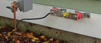
Methods for monitoring the condition of contact connections
Monitoring the condition of contact connections using a measuring rod with a millivoltmeter
The heating of the contacts is determined during the period of maximum load. Since contact metals have significant heat capacity and thermal conductivity, it is difficult to determine a contact defect.
Note. In operation, a more accurate assessment of the condition of the contacts is possible not by heating, but by measuring the magnitude of the voltage drop in the section of the circuit containing the contact connection when operating current flows through the contact or by measuring the magnitude of the contact resistance using a millivoltmeter and an ammeter (or microohmmeter).
The measurement is carried out under operating voltage with a measuring rod with a millivoltmeter mounted on it. The measurement method is based on comparing the voltage drop in the area having a contact connection (Fig. 3, a
), with a voltage drop across a section of the entire wire (Fig. 3,
a
) at a constant load current.
Rice.
3. Position of the rod head when measuring voltage drop: a - at the wire contact; b - on a section of wire
Rice.
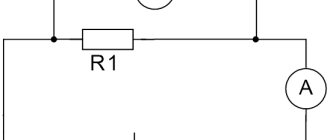
4. Scheme for measuring the resistance of a contact connection using the millivoltmeter and ammeter method.
Monitoring the condition of contact connections using the ammeter-voltmeter method.
During the repair of switches, disconnectors and separators, the direct current resistance of the contact system of these devices is measured. In this case, the resistance of the entire current-carrying circuit of each phase of the switch or disconnector (output-output) is measured.
The method of ammeter and voltmeter or microohmmeter has become widespread in the practice of measuring the resistance of a contact system (Fig. 4). However, more accurate results are obtained by measuring with a double bridge.
Standards for each type
In order to understand what regulatory and operational indicators should be for each type:
- For electrical installations. Ground resistance measurements should be carried out in close proximity to the substation. Depending on the load, this figure can be 60, 30 or 15 Ohms. It is also worth considering natural grounding electrodes - for them these values should be 8, 4 or 2 Ohms, respectively. All three quantities depend on the network voltage. 60 and 8 Ohms are allowed for a single-phase network of 200 volts. 30 and 4 Ohms - for three-phase with a voltage of 380 volts. The minimum values (15 and 2 Ohms) are for 660 volts. During operation, the resistance of the ground loop should also not fall below the values described in the paragraph above.
- For a distribution point or substation. For installations with voltages above 100 kilovolts (100 thousand volts), the grounding conductivity during the commissioning of the network and during its operation also remains unchanged and is 0.5 Ohm. In this case, the mandatory requirements for testing are a solid grounding type and connected to a neutral circuit. There are also standards for less powerful installations, in which the voltage lies between 3 and 35 kilovolts. In this case, you need to divide 250 by the calculated ground fault current - the resulting value will be the required resistance in Ohms. The indicator, according to PTEEP, should not exceed 10 Ohms in any case.
- For overhead power lines. It is calculated depending on the conductivity of the soil on which the power line supports stand:
- for soil with a resistivity of less than 100 Ohms per meter - 10 Ohms;
- with a resistivity of 100...500 Ohms per meter - 15 Ohms;
- with a resistivity of 500...1000 Ohms per meter - 20 Ohms;
- with a resistivity of 1000...5000 Ohms per meter - 30 Ohms.
For power lines with a current voltage of less than 1000 volts - up to 30 Ohms (for supports with lightning protection). Otherwise, the resistance should be 60, 30 or 15 ohms for networks with voltages up to 660, 380 or 220 volts, respectively.
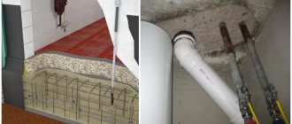
Technical literature often talks about grounding and grounding. Indeed, the issue of grounding in houses and apartments arose in our country relatively recently. Even when communist brigades electrified the country, only phase and neutral were supplied to village houses. They were silent about the grounding wire. Firstly, they saved aluminum as a strategic metal for aircraft, and secondly, few people cared about the problems of protecting the population from electric shock, and thirdly, they did not think about grounding as an effective measure to protect people. Enough time has passed for the communists to disappear, and with them the country they ruled, but the monuments they left behind still stand. Monuments stand, but houses are destroyed.In our houses, only water supply, sewer and gas pipes, as well as floor panels, are grounded. At the same time, the gas pipeline pipes are not suitable for grounding due to the explosive gas that flies through them. Sewage pipes cannot be used for grounding either. Although the sewer system is entirely made of cast iron, the joints of the cast iron pipes are sealed with cement, which is a poor conductor. Water supply pipes seem to be a good grounding device, but you need to take into account that the pipes are not laid in the ground, but in a layer of insulation in special channels. The most reliable grounding is from the floor distribution board.
At the enterprises, everything was initially done correctly and everything that was possible was grounded. In addition to grounding, enterprises use grounding. Many people mistakenly believe that grounding is the wiring in the socket from the neutral wire to the ground contact. The concepts of “grounding” and “zeroing” are closely related to the concept of neutral.
Neutral is the point where three phases converge through the star-connected windings in a transformer. If this point is connected to grounding conductors, a solidly grounded neutral of the transformer is formed, and the overall system is called grounded. If you weld a bus to this point and connect it to all devices and devices, then the equipment will be grounded.
If the neutral is connected to the neutral bus (without grounding electrodes), then an isolated neutral of the transformer is formed, and the overall system is called neutralized. If this bus is connected to all devices and devices, then the equipment will be zeroed.
The idea is that current flows through a grounded or neutralized conductor only when there is a phase imbalance, but this is for a transformer and during emergency operating conditions. You cannot choose whether to ground or ground the equipment. This has already been done at the substation. Typically a solidly grounded neutral is used.
If, for example, the motor winding of a washing machine breaks down and resistance appears between the body and the winding, then there will be a potential on the body of the washing machine that can be detected with an indicator screwdriver. If the machine is not grounded, then when you touch the body, the potential of the machine will become the potential of your hand, and since the bathroom where the machine is located is a particularly dangerous room from the point of view of electric shock and therefore the floor is conductive, the leg will acquire zero potential and this means you will receive a shock with a voltage proportional to the potential of the arm. If the machine is grounded, then in theory the circuit breaker will trip. If the machine is grounded, the potential will spread around the entire machine and upon contact, the potentials of the arm and leg will be the same. You just need to take into account that the current spreads around and when you walk, your legs are under different potentials. And, of course, you can get a stress shock.
Grounding application criteria
Protective grounding is an intentional electrical connection to the ground or its equivalent of metallic non-current-carrying parts of electrical installations that may be energized.
Protective grounding is used in networks with voltages up to 1000 V AC - three-phase three-wire with a solidly grounded neutral; single-phase two-wire, isolated from ground; two-wire DC networks with an isolated midpoint of the current source windings; in networks above 1000 V AC and DC with any neutral mode.
Grounding is mandatory in all electrical installations at voltages of 380 V and above alternating current, 440 V and above direct current, and in rooms with increased danger, especially dangerous and in outdoor installations at voltages of 42 V and above alternating current, 110 V and above direct current; at any voltage in explosive areas.
Depending on the location of the grounding conductors relative to the grounding equipment, two types of grounding devices are distinguished - remote and contour.
With a remote grounding device, the ground electrode is placed outside the site on which the grounded equipment is located.
With a contour grounding device, the grounding electrodes are placed along the contour (perimeter) of the site on which the equipment to be grounded is located, as well as inside this site.
In open electrical installations, the housings are connected directly to the ground electrode by wires. A grounding line is laid in buildings, to which grounding wires are connected. The grounding line is connected to the ground electrode in at least two places.
As grounding conductors, first of all, natural grounding conductors should be used in the form of underground metal communications (with the exception of pipelines for flammable and explosive substances, heating pipes), metal structures of buildings connected to the ground, lead sheaths of cables, casing pipes of artesian wells, wells, pits, etc.
As natural grounding conductors of substations and distribution devices, it is recommended to use grounding conductors of the supports of outgoing overhead power lines connected to the grounding device of the substations or distribution device using lightning protection cables of the lines.
If the resistance of natural grounding conductors Rз satisfies the required standards, then the installation of artificial grounding conductors is not required. But this can only be measured. It is impossible to calculate the resistance of natural grounding conductors.
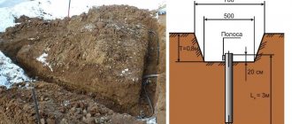
When natural grounding conductors are absent or their use does not give the desired results, artificial grounding conductors are used - rods made of angle steel measuring 50X50, 60X60, 75X75 mm with a wall thickness of at least 4 mm, length 2.5 - 3 m; steel pipes with a diameter of 50–60 mm, a length of 2.5–3 m with a wall thickness of at least 3.5 mm; rod steel with a diameter of at least 10 mm, length up to 10 m or more.
Grounding conductors are driven in a row or along a contour to a depth at which 0.5-0.8 m remains from the upper end of the grounding conductor to the surface of the earth. The distance between vertical grounding conductors must be at least 2.5-3 m.
To connect vertical grounding conductors to each other, use steel strips with a thickness of at least 4 mm and a cross-section of at least 48 sq. mm or a steel wire with a diameter of at least 6 mm. The strips (horizontal grounding conductors) are connected to the vertical grounding conductors by welding. The welding area is coated with bitumen for moisture insulation.
Grounding lines inside buildings with electrical installations with voltages up to 1000 V are made with a steel strip with a cross-section of at least 100 sq. mm or round steel of the same conductivity. Branches from the main line to electrical installations are made with a steel strip with a cross-section of at least 24 sq. mm or round steel with a diameter of at least 5 mm.
The standardized resistances of grounding devices are given in Table 1.
Table 1. Permissible resistance of the grounding device in electrical installations up to and above 1000 V
The highest permissible values of Rз, Ohm
| Characteristics of electrical installations | |
| Rз < 0.5 | For electrical installations with voltages above 1000V and rated ground fault current Iз < 500A |
| Rз = 250 / Iз < 10 | For electrical installations with voltages above 1000V and rated ground fault current Iз < 500A |
| Rз = 125 / Iз < 10 | Provided that the grounding device is common for electrical installations with voltages up to and above 1000 V and a calculated ground fault current Iз < 500 |
| Rз < 2 | In electrical installations with voltage 660/380 V |
| Rз < 4 | In electrical installations with voltage 380/220 V |
| Rз < 8 | In electrical installations with voltage 220/127 V |
Estimated ground fault currents are taken according to power system data or by calculations. In principle, when building a cottage, ground fault current is not needed. This is a question of grounding the substation.
The calculation of grounding using the utilization coefficient method is carried out as follows.
1. In accordance with the PUE, the required grounding resistance Rз is established according to Table 1.
2. Determine by measurement, calculation or based on data from operating similar grounding devices the possible resistance to spreading of natural grounding conductors Re.
3. If ReRз, then an artificial grounding device is required.
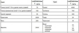
4. Determine the soil resistivity ρ from Table 2. When making calculations, these values should be multiplied by a seasonality factor, depending on the climatic zones and the type of ground electrode (Table 3).
Table 2. Approximate values of soil and water resistivities p, Ohm•m
| Soil name | Specific resistance, Ohm•m |
| Sand | 700 |
| Sandy loam | 300 |
| Loam | 100 |
| Clay | 40 |
| garden soil | 40 |
| Clay (layer 7-10 m) or gravel | 70 |
| Marl, limestone, coarse sand with boulders | 1000-2000 |
| Rocks, boulders | 2000-4000 |
| Chernozem | 20 |
| Peat | 20 |
| River water (on plains) | 10-100 |
| Sea water | 0,2-1 |
Approximate distribution of CIS countries by climatic zones:
1 zone: Arkhangelsk, Kirov, Omsk, Irkutsk regions, Komi, Ural;
Zone 2: Leningrad and Vologda regions, central part of Russia, central regions of Kazakhstan, southern part of Karelia.
Zone 3: Latvia, Estonia, Lithuania, Belarus, southern regions of Kazakhstan; Pskov, Novgorod, Smolensk, Bryansk, Kursk and Rostov regions.
Zone 4: Azerbaijan, Georgia, Armenia, Uzbekistan, Tajikistan, Kyrgyzstan, Turkmenistan (except mountainous areas), Stavropol Territory, Moldova.
Table 3. Characteristics of climatic zones and values of the Kc coefficient
| Data characterizing climatic zones and the type of grounding electrodes used | Climatic zones of the CIS | |||
| 1 | 2 | 3 | 4 | |
| Climatic characteristics of the zones: | ||||
| average long-term low temperature (January), °C | from -20 to -15 | from -14 to -10 | from -10 to 0 | from 0 to +5 |
| average long-term highest temperature (July), °C | from +16 to +18 | from +18 to +22 | from +22 to +24 | from +24 to +26 |
| average annual precipitation, mm | ~400 | ~500 | ~500 | ~300-500 |
| Duration of water freezing, days | 190-170 | 150 | 100 | 0 |
| The value of the Kc coefficient when using rod electrodes with a length of 2 - 3 m and a depth of their top of 0.5 - 0.8 m | 1,8-2 | 1,5-1,8 | 1,4-1,6 | 1,2-1,4 |
| The value of the K's coefficient when using extended electrodes and the depth of their top is 0.8 m | 4,5-7,0 | 3,5-4,5 | 2,0-2,5 | 1,5-2,0 |
| The value of the Kc coefficient with a length of 5 m and a top depth of 0.7-0.8 m | 1,35 | 1,25 | 1,15 | 1,1 |
5. Determine the resistance, Ohm, to the spreading of one vertical grounding conductor - a round rod (tubular or angular) in the ground:
Table 4. MV utilization factors for vertical electrodes made of pipes, angles or rods placed in a row without taking into account the influence of the communication band
| Ratio of the distance between the electrodes to their length: a/l | Number of electrodes Mv | Mv |
| 1 | 2 | 0,84-0,87 |
| 3 | 0,76-0,80 | |
| 5 | 0,67-0,72 | |
| 10 | 0,56-0,62 | |
| 15 | 0,51-0,56 | |
| 20 | 0,47-0,50 | |
| 2 | 2 | 0,90-0,92 |
| 3 | 0,85-0,88 | |
| 5 | 0,79-0,83 | |
| 10 | 0,72-0,77 | |
| 15 | 0,66-0,73 | |
| 20 | 0,65-0,70 | |
| 3 | 2 | 0,93-0,95 |
| 3 | 0,90-0,92 | |
| 5 | 0,85-0,88 | |
| 10 | 0,79-0,83 | |
| 15 | 0,76-0,80 | |
| 20 | 0,74-0,79 |
Table 5. MV utilization factors for vertical electrodes made of pipes, angles or rods placed along the contour without taking into account the influence of the communication band
| Ratio of the distance between the electrodes to their length a/l | Number of electrodes Mv | Mv |
| 1 | 4 | 0,66-0,72 |
| 6 | 0,58-0,65 | |
| 10 | 0,52-0,58 | |
| 20 | 0,44-0,50 | |
| 40 | 0,38-0,44 | |
| 60 | 0,36-0,42 | |
| 100 | 0,33-0,39 | |
| 2 | 4 | 0,76-0,80 |
| 6 | 0,71-0,75 | |
| 10 | 0,66-0,71 | |
| 20 | 0,61-0,66 | |
| 40 | 0,55-0,61 | |
| 60 | 0,52-0,58 | |
| 100 | 0,49-0,55 | |
| 3 | 4 | 0,84-0,86 |
| 6 | 0,78-0,82 | |
| 10 | 0,74-0,78 | |
| 20 | 0,68-0,73 | |
| 40 | 0,64-0,69 | |
| 60 | 0,62-0,67 | |
| 100 | 0,59-0,65 |
6. When constructing simple grounding conductors in the form of a short row of vertical rods, the calculation can be completed at this point and the conductivity of the connecting strip cannot be determined, since its length is relatively short (in this case, the actual resistance of the grounding device will be somewhat overestimated). As a result, the general formula for calculating the resistance of vertical grounding conductors looks like this:
Where
p — Approximate values of soil and water resistivity, Ohm•m, table 2
KS - Characteristics of climatic zones and coefficient values, table 3.
L – length of vertical ground electrode, m
d – diameter of vertical ground electrode, m
t' – length from the ground surface to the middle of the vertical ground electrode, m
Mv is the coefficient of use of vertical grounding electrodes, depending on the number of grounding electrodes and the distance between them (Tables 4, 5). The preliminary number of vertical grounding conductors for determining Mv can be taken equal to Mv = rv/Rz
a – the distance between vertical grounding conductors (usually the ratio of the distance between vertical grounding conductors to their length is taken equal to a/l=1;2;3)
Rз - Permissible resistance of the grounding device in electrical installations up to and above 1000 V, table 1
in this case l>d, t0>0.5 m;
for a corner with flange width b, d=0.95b is obtained.
For horizontal grounding conductors, the calculation is carried out using the same utilization factor method
1. Determine the resistance, Ohm, to the spreading of the horizontal ground electrode. For round rod section:
Table 6. Usage factors Mg of a horizontal strip electrode (pipes, angles, strips, etc.) when placing vertical electrodes in a row.
| Ratio of distance between electrodes to length a/l | Mg with the number of electrodes in a row | |||||||
| 4 | 5 | 8 | 10 | 20 | 30 | 50 | 65 | |
| 1 | 0,77 | 0,7 | 0,67 | 0,62 | 0,42 | 0,31 | 0,2 | 0,2 |
| 2 | 0,89 | 0,9 | 0,79 | 0,75 | 0,56 | 0,46 | 0,4 | 0,34 |
| 3 | 0,92 | 0,9 | 0,85 | 0,82 | 0,68 | 0,58 | 0,5 | 0,47 |
Table 7. Usage coefficient Mg of a horizontal strip electrode (pipes, angles, strips, etc.) when placing vertical electrodes along the contour.
| Ratio of distance between electrodes to length a/l | Mg with the number of electrodes in the ground loop | ||||||||
| 4 | 5 | 8 | 10 | 20 | 30 | 50 | 70 | 100 | |
| 1 | 0,45 | 0,4 | 0,36 | 0,34 | 0,27 | 0,24 | 0,21 | 0,2 | 0,19 |
| 2 | 0,55 | 0,48 | 0,43 | 0,4 | 0,32 | 0,3 | 0,28 | 0,26 | 0,24 |
| 3 | 0,65 | 0,64 | 0,6 | 0,56 | 0,45 | 0,41 | 0,37 | 0,35 | 0,33 |
Where
p - approximate values of soil and water resistivity, Ohm•m, table 2
KS - characteristics of climatic zones and coefficient values, table 3.
L – length of horizontal ground electrode, m
d – diameter of the horizontal ground electrode, m
t' – length from the ground surface to the middle of the horizontal ground electrode, m
Mv is the coefficient of use of horizontal grounding conductors, depending on the number of grounding conductors and the distance between them (Tables 6, 7).
a – the distance between horizontal grounding conductors (usually the ratio of the distance between horizontal grounding conductors to their length is taken equal to a/l=1;2;3)
Rз - Permissible resistance of the grounding device in electrical installations up to and above 1000 V, table 1
Here l>d, l>>4t'. For a strip of width b, d=0.5b is obtained.
Example 1
Calculate the grounding device of a 35/10 kV factory substation located in the second climatic zone. 35 and 10 kV networks operate with an ungrounded neutral. On the 35 kV side Iz=8A, on the 10 kV side Iz=19A. The substation's own needs are powered by a 10/0.4 kV transformer with a grounded neutral on the 0.4 kV side; there are no natural grounding electrodes. Specific soil resistivity at normal humidity p=62 Ohm*m. The electrical equipment of the substation occupies an area of 18*8 sq.m.
Solution
Let's estimate the number of vertical electrodes to be 10 pcs. according to table 5, Mv=0.58.
Let's find the number of vertical electrodes
If Nв <10, everything is fine and you can accept Nв = 9 electrodes.
If Nв>10, it is necessary to increase МВ, which will accordingly increase the approximate number of electrodes.
Let's estimate the number of horizontal electrodes to be 50 pcs. according to table 6, Mg=0.2.
If Ng<50, everything is fine and you can accept Ng=49 electrodes.
If Ng>50, then it is necessary to increase Mv, which will accordingly increase the approximate number of electrodes.
Example 2
Calculate the grounding device for a cottage in Belarus. The cottage stands on clay soil, therefore the soil resistivity is p=40 Ohm*m. For grounding, fittings with a diameter of 12 mm and a length of 2 meters are used.
Solution
According to table 1 – Rз=4
According to table 2 – p=40 Ohm*m
According to table 3 – Kc=1.6
The electrodes will be placed in a row, so using Table 4 we will estimate the number of vertical electrodes, for example 10 pcs. Mv=0.62 The driving depth of all electrodes from the surface of the earth is 0.7 meters, plus half the length of a two-meter electrode and therefore t'=1.7 meters.
Let's find the number of vertical electrodes
If Nв>10, then it is necessary to increase МВ, which will accordingly increase the approximate number of electrodes.
Using Table 4, we estimate the number of vertical electrodes, a total of 15 pieces. Mv=0.56
If Nв <15, everything is fine and you can accept Nв = 14 electrodes.
Let's go the other way and weld a frame from pins, burying it 0.8 meters underground. This is how horizontal grounding conductors are obtained.
According to table 1 – Rз=4
According to table 2 – p=40 Ohm*m
According to table 3 – Kc=1.6
The driving depth of all electrodes from the surface of the earth is 0.7 meters, plus half the length of a two-meter electrode and therefore t'=1.7 meters
Let's estimate the number of horizontal electrodes, for example 30 pcs. according to table 6, Mg=0.24
If Ng>30, then it is necessary to increase Mg, which will accordingly increase the approximate number of electrodes.
Using Table 6, let’s estimate the number of horizontal electrodes, for example 50 pcs. Mg=0.21
If Ng<10, everything is fine and you can accept Ng=37 electrodes.
Grounding takes into account the Earth's ability to conduct electricity. Grounding electrodes are usually made of steel. Over time, steel rusts and breaks down, and the grounding is lost. This process is irreversible, but zinc coated steel rods can be used. Zinc is also a metal, but it is not susceptible to rust as long as there is a layer of zinc. When the zinc is washed out over time or worn away by mechanical means, for example, when driving electrodes into hard soil, stones can peel off the coating, then the corrosion rate will double. Sometimes special electrodes coated with copper are used.
Grounding rods can be taken from those that were used as reinforcement for the concrete foundation. They cannot be painted or coated with resinous compounds - the resin will act as an insulator and there will be no grounding at all. The longer the rods, the fewer of them will be needed for grounding, but the more difficult it is to drive them into the soil. Therefore, first you need to dig a trench 1 meter deep. Hammer a piece of pre-sharpened reinforcement into the trench so that it protrudes no more than 20 centimeters from the bottom of the trench. Then, after 2 meters, the next reinforcement is driven in, and so on according to calculation. Next, reinforcement is placed at the bottom of the trench and welded to all the driven pins. The welding area must be coated with bitumen for moisture insulation. This is done because reinforcement 12 millimeters thick will rot in the ground for a very long time, but the welding area is relatively small in area, but the most critical.
After driving all the electrodes, you can conduct the experiment. We pull the extension cord out of the house. The voltage source must come from a pole from the substation. You cannot use an autonomous source such as a generator for testing - there will be no closed circuit. We find a phase on the extension cord and connect one wire from the light bulb, and with the second wire we touch the scalded electrodes. If the light bulb is lit, then we measure the voltage between the phase wire and the grounded electrodes, the voltage should be 220 V, but the light bulb should glow quite brightly. You can also measure the current through a 100 W light bulb. If the current is approximately 0.45 A, everything is fine, but if the current is much less, you should add ground rods.
It is necessary to achieve the normal glow of the light bulb and the current within normal limits. After this, the welding areas are filled with bitumen and a piece of reinforcement is removed from the trench, attaching it to the house. After this, the trench can be backfilled. The removed piece of reinforcement must be welded to the electrical distribution board in the cottage. Disconnect all points from the shield with copper cables.
What does grounding resistance depend on?
As mentioned above, current has one important feature - it flows through that part of the circuit that least resists it. The resistance value itself depends on many factors:
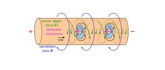
- Material . A number of materials have a special (atomic) structure, which implies the presence of a large number of free electrons. If such materials are exposed to any magnetic field or connected to a power source, they easily conduct electric current. For the most part, this statement applies to metals. Other materials have no free electrons and their resistance to current is extremely high. If the voltage (the force “pushing” the electrons) is below the permissible value, then the conductivity will be zero or extremely small values. If the indicator is exceeded, a breakdown will occur and the resulting deposit will have the properties of a conductor. It is logical that only representatives of the first group of materials can be grounding materials - it is this group that provides the minimum resistance.
- Its temperature . Temperature determines how quickly electrons move within a material. Therefore, the lower it is for a conductor, the better it conducts charge. The inverse dependence is also in the nature of a direct proportion - after its increase, its resistance will fall. The calculation of grounding resistance must be made taking this parameter into account.
- Presence of impurities . The main part of the conductors is made of copper. Old wires were made of aluminum, but such solutions have several disadvantages. Unfortunately, cables and wires made of this material overheat and melt faster, and the resistance of industrially mined aluminum is lower than that of copper. Chemically pure metal is the best conductor, surpassing even silver in conductivity. The thing is with impurities: they have much higher resistance values. The same point should be taken into account when calculating grounding.
It is clear that ideally the resistance should be minimal - for this you need to use a copper circuit with a large cross-section. But the fact is that copper oxidizes quickly, and the cost of such a solution will be extremely high. Consequently, standards have been developed for the minimum grounding threshold. This indicator does not need to be exceeded so that at the right moment under load the circuit fulfills its assigned function and discharges the charge to the ground.
How to calculate a ground loop: step-by-step instructions
The project is created in several stages.
Step #1. Material selection
The metal and its profile are selected according to the above table 1.7.104. In production, they use those materials that are available or easiest to purchase in a particular area. The main condition is to comply with the required cross-section.
Step #2. Design Definition
Here we ask:
- driving depth of vertical grounding conductors H;
- the distance between them D;
- their number N.
The calculation assumes their arrangement in a line, and not in a triangle, when the shielding area increases. But if necessary, this option can be easily recalculated.
The direction of the line is selected taking into account local conditions so that it does not intersect with other highways, for example, sewerage, water supply, gas supply.
The driving depth is determined experimentally on one control specimen. A hole 0.7 meters deep is dug for it and a test rod is driven into it.
At the same time, the effort expended and the features of the technology are assessed. If you pour a bucket of water into the hole and let it soak into the soil for at least half an hour, then driving it in will require less physical effort.
The recommended length for a prototype is usually 2-2.5 meters. In short, rods are made only for very dense soils.
The distance between the vertical electrodes is chosen as a multiple of their length: this makes it possible to better take into account the coefficients of mutual influence.
The number of vertical grounding rods determines the length of the connecting strip, taking into account the section of the supply to the house, and its characteristics are also included in the design calculations.
When the configuration and dimensions are selected, then proceed to the next stage.
Step #3. Calculation of electrical resistance of the selected circuit
Calculations using mathematical formulas allow a preliminary assessment of the assembled structure. If it meets the standard, then you can begin to manufacture it. Otherwise, adjustments are made to the circuit by increasing the number of electrodes, deepening them, or increasing the distances.
First, the resistance of single grounding conductors is calculated, taking into account their shape and method of burial.
When the calculation is completed and verified, we begin to determine special utilization factors. They take into account the degree of shielding and mutual influence of the electrodes.
I present their most common part in a table.
After determining the influence coefficients, you can proceed to the general calculation of the resistance of the grounding device. I'll give you the formula.
The result obtained may fall within the standardized 30 ohms or be higher. If it does not meet the requirements of the PUE, then something will need to be added to the design or the dimensions changed. After this, you need to make a new calculation and achieve a positive result.
Calculations can be done manually using formulas on paper or use the online calculator attached below.
Having calculated several options for the design of the grounding structure, you will remember its features well and understand the assembly technology. And this will help to avoid mistakes and create a reliable device for long-term operation.
Calculation formula
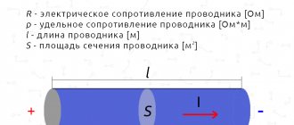
Formula for calculating the grounding resistance of a single vertical ground electrode:
where: ρ - soil resistance per unit length (Ohm×m) L - length of the ground electrode (in meters) d - width of the ground electrode (in meters) T - distance from the ground surface to the middle of the ground electrode (in meters)
For electrolytic grounding:
Formula for calculating the grounding resistance of a single horizontal electrode with the addition of a correction factor:
Where:
ρ—soil resistance per unit length (Ohm×m); L is the length of the ground electrode (in meters); d is the width of the ground electrode (in meters); T is the distance from the earth’s surface to the middle of the ground electrode (in meters); C is the relative content of electrolyte in the surrounding soil.
The C coefficient varies from 0.5 to 0.05. Over time, it decreases, as the electrolyte penetrates into the soil to a larger volume, while increasing its concentration. As a rule, it is 0.125 after 6 months of leaching of electrode salts in dense soil and after 0.5–1 month of leaching of electrode salts in loose soil. The process can be accelerated by adding water to the electrode during installation.
The calculated electrical resistivity of the soil (Ohm×m) is a parameter that determines the level of “electrical conductivity” of the earth as a conductor, that is, how well the electric current from the ground electrode will flow in such an environment.
This is a measured value that depends on the composition of the soil, the size and density of its particles adhering to each other, humidity and temperature, and the concentration of soluble chemicals in it (salts, acidic and alkaline residues).
Results and conclusions
Grounding is an important element of an electrical circuit that provides protection against short circuits, electric shock or lightning strikes in one of its sections. The key indicator here is resistance: the lower it is, the more current the circuit will “carry” and the lower the likelihood of a serious shock or damage to the equipment. Grounding resistance is regulated by two documents: PUE and PTEEP. The first is used to receive a newly commissioned section of the network, the second is used to control an already operating section.
Control standards that are designed to check the quality of grounding and the operation of the circuit under full load conditions cannot be neglected. Procedures are carried out both immediately after the creation of the chain and during its use. The frequency of checks depends on the load on the network and the purpose for which the circuit is used. The norms of resistance are not different at all. There are three types of standards: for power lines, transformers and electrical installations. As the operating voltage increases, the maximum resistance value increases exponentially. A number of specific indicators are also taken into account (for example, soil conductivity). Based on it, you can obtain the maximum regulated resistance.
The main ways to increase the efficiency of the ground electrode is to use different conductor configurations. The key task is to maximize the area of direct contact of the circuit with the ground. For this, one or more conductors are used. In the latter case, they can be connected both in series and in parallel.
Also, to measure the resistance of the grounding loop, it is important to know the correction factors - for example, when calculating the minimum permissible grounding resistance, the specific content of the material in the soil and the re-grounding resistance are also taken into account. To obtain this indicator you need to use special equipment.
Grounding Configuration
Grounding resistance directly depends on the area of electrical contact between the grounding electrodes and the ground, which should be as large as possible. The larger the surface area of the ground electrode, the lower the grounding resistance.
Most often, due to the least installation complexity, a vertical electrode in the form of a rod/pipe/angle is used as a grounding electrode.
To increase the contact area of the ground electrode with the ground:
- the length (depth) of the electrode increases
- several short electrodes connected together are used, placed at some distance from each other (ground loop). In this case, the areas of individual electrodes are simply added together, which is described in detail on a separate page on grounding calculations.