The article will touch upon the issue of installing grounding in a private home, country house, or small production facility with your own hands.
Many people mistakenly believe that grounding is an unnecessary, additional thing that, out of harm, is required by the energy supply organization or inspection inspectors. The most important thing that any consumer of electricity should understand is that grounding is an integral part of any power supply. This is the same necessity as installing automatic switches in the switchboard, metering devices and other equipment.
To perform grounding efficiently, it is necessary to carry out a large amount of excavation work. Roughly calculate that, at a minimum, you will have to manually dig one cubic meter of earth. You will also need a welding machine and welding skills.
The best option is to do the grounding yourself, since not all electricians like to do it, and those who do, for the most part, do it poorly.
So, how is a ground loop made correctly?
There are two most common options for a ground loop - a triangle and a linear one, in the form of a continuous strip along the house.
Both are correct. Which one to choose is up to you to decide, based on the free space near the house.
delta ground loop
linear ground loop
Ground loop material
The grounding loop consists of vertical and horizontal grounding conductors. Material from which it is not recommended to make vertical grounding conductors:
- ⚡corrugated fittings
- ⚡round steel with a diameter of less than 10mm
What can be made from:
- ⚡round steel 14mm or more (with a smaller diameter it is difficult to drive an electrode into the ground)
- ⚡steel corner with dimensions of at least 40*40*5
The end of the angle or round steel is cut at an angle of 30 degrees. This is the most optimal angle for steel to enter the ground.
The horizontal grounding conductor is made from a steel strip 40*4.
Dimensions and distances for ground electrodes
Mandatory conditions that must be observed when installing grounding in a private house:
- ⚡the length of the electrode that is driven into the ground. It should be at least 2.5-3 meters
Initially, it is better to take an electrode 3 m long. Since in the process of hammering it with a sledgehammer, the part that is hit will be flattened. In the end, you will have to cut off a few centimeters of such a flattened electrode with a grinder.
- ⚡distance between electrodes. It should also be 2.5-3 meters
Regardless of what type of contour you have - in the form of a triangle or a straight line. This is due to the phenomenon of current spreading from grounding conductors. If the electrodes are hammered closer than 2.5 m, then it turns out that it makes no difference how many electrodes you hammered in.
They will work almost like one electrode.
- ⚡ deepening of the trench from the planning mark of the ground - 0.7-0.8 m
The trench is a place to lay the strip connecting the electrodes. With less deepening of the trench, the strip will be exposed to precipitation and a rapid corrosion process. With greater depth, the risk of exposure to dampness from groundwater again arises.
- ⚡the distance of the grounding loop from the foundation of the house is at least 1 m
- ⚡after excavating the trench, it is sprinkled with sand for better drainage of water from the horizontal ground electrode.
Depth of electrodes
When all the material and trenches are ready, the process of hammering the electrode begins. To facilitate the process, add a little water to the hole. The vertical electrode can be hammered in two ways:
- ⚡sledgehammer
- ⚡a powerful hammer drill or jackhammer with an attachment
Initially, the top end of the electrode will be at a high height. Therefore, you will need a stepladder.
There is no need to drive the entire electrode into the ground completely. Leave at least 20cm on the surface, as the strip will need to be welded in this place. The length of the welding seam is at least 6-10 cm. The seam itself is painted over.
Do not paint horizontal or vertical grounding conductors under any circumstances.
This will increase the grounding resistance and worsen the connection to the ground.
To improve the ground loop, you can connect it to existing metal structures buried in the ground - for example, a fence.
Zahisne grounded
Protective earthing (English: protective earthing, German: Schutzerdung, f) - grounding of a point or point in the system during the installation of the system or in the possession, using the method of electrical safety.
Dry grounding is implemented in the form of a special electrical connection from the ground or an equivalent of strumoid elements possessed, which are not subject to voltage, but during operation can be damaged work under stress, for example, in case of damaged insulation, defects in arc-extinguishing devices, switching devices, in emergency situations too bad.
Dry grounding is a simple, effective and widespread way to protect people from electrical shock from reaching metal surfaces that were exposed to voltage. This will ensure that the difference in potentials between the properties that appeared under the voltage and the ground is reduced to a safe value. Vikorist is used in a three-phase three-wire circuit with a voltage of up to 1000 V with an insulated and solidly grounded neutral and more than 1000 V - with a sufficient neutral mode.
The structural elements of chemical grounding are: grounding conductors (metal conductors located in the ground) and grounding conductors (connecting the equipment that is grounded from the grounding conductor).
Ground connection to electrical panel
When the circuit is made, it must be connected to the electrical panel. Here you can no longer use a strip, but a wire with a diameter of 10 mm. It is connected to the horizontal grounding conductor by welding, and to the panel body using a bolted connection.
You can also bring a strip of horizontal grounding conductor to the surface near the switchboard, and by welding a bolt to the strip, connect the circuit to the switchboard with a copper conductor with a cross-section of 10 mm2. The bolted connection must be on the surface and accessible for inspection.
After checking the reliability of the connection of the welds, the trench is covered with earth. This completes the installation of the ground loop.
Results
In conclusion, we note that a fairly common method of connecting individual elements of the ground bus is welding.
It fully satisfies the GOST requirements for arranging reliable contacts. At the same time, the use of a welding device for assembly purposes ensures a strong connection with a guarantee of high conductivity.
We also note that the quality of bolted connections is ensured by reliable crimping of the cable lugs of the supply wires. In the same way (by bolting) the busbar in the tip is connected to the cabinet body.
Source
General provisions for grounding a home
The main power supply circuit for a private home is the TN-CS circuit. Therefore, when dividing the PEN conductor into PE and N at the power supply input to the house, it requires installation of re-grounding (for more details, read the article on power supply and grounding of a private house). The most common type of grounding of a private house is with pin grounding electrodes connected in a loop.
Read also: Cleaning weld seams after welding
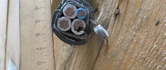
The grounding rod has long been used to ground a private house. Unlike a modular-pin deep grounding electrode, a pin-type grounding electrode can be called a truly “folk way” of grounding a private house. This is due to the low cost of the ground electrode itself and the ease of its installation, which does not require special tools. For example, to install a deep ground electrode, you need to buy the ground electrode itself and for installation you will need an electric hammer drill. To install a pin grounding switch, 6 (six) metal corners 3 meters long are required. Three corners with shelf dimensions of 50x50 mm and a wall of 3 mm and three corners 40x40 mm. The 50x50 mm corner can be replaced with a metal pipe with a diameter of 16 mm and a wall of 3 mm.
Let us analyze the designs of pin grounding conductors.
Basic terms and meanings
The basic terminology is regulated by the IEC 60364-1 standard and the Electrical Installation Regulations.
Conductive part is a part of an electrical installation that has the power to conduct electrical flow.
Conductor (English conductor) - a conductive part, intended for conducting electrical power.
Live part is a conductor or a conductive part that is in the process of normal operation under voltage, including a neutral conductor, and not a PEN conductor.
Exposed-conductive-part (English: exposed-conductive-part) is a conductive part of an electrical installation that is accessible to the operator, so that during operation it is not under operating voltage, otherwise it may be exposed to voltage due to deterioration of the insulation of the conductive parts ( for example, housing and electrical equipment).
Extraneous conductive part (eng. extraneous-conductive-part) - a conductive part, which is not a part of the electrical installation, that carries electrical potential, usually the electrical potential of the local ground (for example, the rails of subway tracks are and metal structures, metal pipes and shells communication too)
Protective conductor - a conductor used for electrical safety.
Protective earthing conductor - a grounding conductor used for dry grounding.
PE-conductor (PE in English protectiveearthing - dry grounding) - a dry conductor in electrical installations with a voltage of up to 1 kV, used for protection against electrical shock.
Neutral conductor (N-conductor, English neutral conductor) is a conductor in electrical installations with a voltage of up to 1 kV, electrically connected to the neutral point of the power supply, which is used to distribute electrical energy.
The providnik of the middle point (M-providnik, English Mid-Point Conductor) is a providnik in an elastic band in a crust of 1 sq. Minut, yellow-eating jeanel і vicoristovye for the rosor of the Electricho Yenergya.
PEN conductor (PEN in English protective earth and meutral) is a conductor in electrical installations with voltages up to 1 kV, which combines the functions of dry (PE-) and neutral (N-) conductors
Designs of pin grounding conductors
Pin grounding conductors are installed at a distance of 1 meter from the foundation of the house. The general design principle of pin grounding conductors is as follows:
General design of a pin ground electrode
Metal corners or pipes are driven into the ground. They are called electrodes. The electrodes are driven three meters into the ground and connected to each other with a metal corner. The connection is made by welding. The distance between the electrodes must be at least 1.2 meters. This entire structure is a pin grounding conductor. The grounding conductors are connected to the main grounding bus (GZB) of the house using copper wire PV3 (PV three). The connection of the wire with the grounding conductor and the main switch is bolted using copper cable lugs.
Note: PV3 wire is a single-core wire with copper stranded core and PVC insulation. Operating voltage up to 470 volts at alternating voltage and 1000 volts at constant voltage. The wire is resistant to mechanical bending, shock and linear stretching.
Various designs of pin ground electrode
Triangle. This is a pin grounding design in which electrodes are driven into the ground at the corners of a triangle with sides of 1.3 meters. The distance from the foundation to the nearest vertex of the grounding triangle is 1 meter.
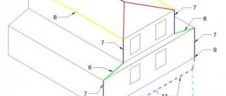
"Crow's Foot". This is a pin grounding design in which electrodes are driven into the ground along the corner of the house. The distance between the electrodes is 3 meters. The distance from the angle electrode to the foundation is 1 meter. The number of crow's foot grounding conductors must correspond to the number of lightning rods installed for the house.
Row grounding. This pin grounding design provides for the arrangement of pin-electrodes in a row every 1.2-1.3 meters.
I repeat, all the corners (pins, electrodes) are driven into the ground to a depth of 3 meters, connected to each other with 40x40x4 mm corners or a 40x4 mm metal strip. Connection using a fold. The pin grounding switch itself is connected to the main grounding bus (GSB) of the house, installed in the water distribution device (WDU) or next to it, with a PV 3 wire. The connection is made using cable lugs.
How to properly drive an electrode into the ground?
Calculation
There are two ways to calculate grounding. We will first look at one that does not require working with formulas and numbers. However, please note that it is only suitable for those who plan to make a ground loop with their own hands.
However, the designed circuit may not be suitable due to the characteristics of the material, the ground or other reasons. And the process of “completing construction” can take a lot of time, and can significantly complicate the scheme. In such a situation, it would, of course, be preferable to know the requirements in advance. In addition, knowledge of the design resistance is necessary when purchasing a modular grounding system.
For calculations, we need to know the resistance of the rods, the length of the horizontal ground (the perimeter of the triangle) and the soil resistance.
The resistance of one vertical grounding electrode is determined by the following formula:
What kind of lighting do you prefer?
Built-in Chandelier
where, R – electrode resistance, Ohm; ρeq – equivalent soil resistivity, Ohm*m; L – electrode length, m; d – electrode diameter, m; T – distance from the middle of the rod to the surface, m.
Fine. Only in order to make calculations, we need to know the resistivity of the soil. To do this, you can use the following table:
| Plastic clay | 20 | Clay semi-solid | 60 |
| Peat | 25 | Semi-solid loam | 100 |
| Plastic loam | 30 | A mixture of clay and sand | 150 |
| Ash, ashes | 40 | Sandy loam wet | 150 |
| garden soil | 40 | Clay gravel | 300 |
| Chernozem | 50 | Sandy loam | 300 |
| Shale | 55 | Wet sand | 500 |
If we are dealing with heterogeneous soil, we should calculate the grounding resistance using a different formula:
where, Ψ – seasonal climate coefficient; ρ1 , ρ2 – soil resistivity (1 – top layer, 2 – bottom); H – thickness of the top layer; t – electrode driving depth.
The seasonal grounding coefficient can be found in the following table, based on the climatic zone of the building.
| Type of ground wires | Climate zone | |||
| I | II | III | IV | |
| Horizontal | 1,8 + 2 | 1,5 + 1,8 | 1,4 + 1,6 | 1,2 + 1,4 |
| Vertical | 4,5 + 7 | 3,5 + 4,5 | 2 + 2,5 | 1,5 |
| Climatic characteristics of zones | ||||
| Average long-term minimum temperature (January) | -20˚С — +15˚С | -14 ˚С — +10 ˚С | -10˚С – 0˚С | 0 ˚С — +5 ˚С |
| Average long-term maximum temperature (July) | +16 ˚С — +18 ˚С | +18 ˚С — +22 ˚С | +22 ˚С — +24 ˚С | +24 ˚С — +26 ˚С |
| Plastic clay | 20 | Clay semi-solid | 60 |
| Peat | 25 | Semi-solid loam | 100 |
| Plastic loam | 30 | A mixture of clay and sand | 150 |
| Ash, ashes | 40 | Sandy loam wet | 150 |
| garden soil | 40 | Clay gravel | 300 |
| Chernozem | 50 | Sandy loam | 300 |
| Shale | 55 | Wet sand | 500 |
Expert opinion
Viktor Pavlovich Strebizh, lighting and electrical expert
Any questions ask me, I will help!
This situation is fraught with malfunctions and breakdowns, not to mention the danger for a person to receive a sensitive discharge by accidentally touching the surface with his hand. If there is something you don’t understand, write to me!
Installation of a pin grounding conductor
Work on installing the pin grounding switch begins with excavation work. For each electrode, you need to prepare a pit in the form of an inverted trapezoid. The depth of the pit should be 80 centimeters. The size of the lower pit at the bottom is 50x50 cm, expanding towards the top to 70x70 cm.
A pin or corner is driven into the ground to a depth of 3 meters using a sledgehammer. There should be 15-20 cm from the bottom level of the pit to the top of the clogged electrode.
Clogged corners and grounding conductors are connected with a metal strip or corners by welding. The entire structure of the pin grounding switch is connected to the main grounding bus (GZSh) by wire PV 3.
After the entire structure of the pin grounding rod from the corner is driven in, connected and assembled, it is logical to cover it with earth. It is better to cover the ends of the ground electrode corner protruding from the pit with clay. It has a high density and distributes electrical flows well.
It is forbidden to fill pits with installed ground electrodes with construction waste. More precisely, the density of construction waste should not exceed 20% (PUE ed. 7. Chapter 1.7)
Modern household appliances and equipment require grounding. Only in this case will manufacturers maintain their guarantees. Residents of apartments have to wait for the networks to be overhauled, while home owners can do everything themselves. How to make grounding in a private house, what is the procedure and connection diagrams - read about all this here.
Types of ground loops
In general, ground loops can be in the form of a triangle, rectangle, oval, line or arc. The best option for a private home is a triangle, but others are also quite suitable.
Grounding in a private house - types of grounding loops
Triangle
Grounding in a private house or country house is most often done with a contour in the form of an isosceles triangle. Why is that? Because with such a structure, in a minimum area we obtain a maximum area for current dissipation. The costs of installing a grounding loop are minimal, and the parameters correspond to the standards.
Most often, grounding in a private house is done with a triangle-shaped circuit
The minimum distance between the pins in the ground loop triangle is their length, the maximum is twice the length. For example, if you drive the pins to a depth of 2.5 meters, then the distance between them should be 2.5-5.0 m. In this case, when measuring the resistance of the ground loop, you will get normal values.
During work, it is not always possible to make the triangle strictly isosceles - stones come across in the right place or other difficult-to-pass areas of soil. In this case, you can move the pins.
Linear ground loop
In some cases, it is easier to make a ground loop in the form of a semicircle or a chain of pins lined up (if there is no free area of suitable dimensions). In this case, the distance between the pins is also equal to or greater than the length of the electrodes themselves.
Read also: Why do you need a ground loop?
With a linear circuit, a larger number of vertical electrodes is necessary so that the dissipation area is sufficient
The disadvantage of this method is that to obtain the required parameters, a larger number of vertical electrodes is required. Since hammering them in is still a pleasure, if there is a meta, they try to make a triangular outline.
Ground loop materials
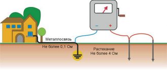
For the grounding of a private house to be effective, its resistance should not be more than 4 ohms. To do this, it is necessary to ensure good contact of the grounding conductors with the ground. The problem is that grounding resistance can only be measured with a special device. This procedure is carried out when putting the system into operation. If the parameters are worse, the act is not signed. Therefore, when doing the grounding of a private house or cottage with your own hands, try to strictly adhere to the technology.
Example of grounding for a private house
Pin parameters and materials
Grounding pins are usually made of ferrous metal. Most often, a rod with a cross-section of 16 mm or larger or a corner with parameters 50 * 50 * 5 mm (5 cm shelf, metal thickness - 5 mm) is used. Please note that reinforcement cannot be used - its surface is hardened, which changes the distribution of currents, and in addition, in the ground it quickly rusts and collapses. What is needed is a rod, not reinforcement.
Possible electrode profiles
Another option for arid regions is thick-walled metal pipes. Their lower part is flattened into a cone, and holes are drilled in the lower third. To install them, holes of the required length are drilled, since they cannot be driven in. When soils dry out and grounding parameters deteriorate, a saline solution is poured into the pipes to restore the dissipative capacity of the soil.
The length of the grounding rods is 2.5-3 meters. This is sufficient for most regions. More specifically there are two requirements:
- the grounding loop rod must extend into the ground below the freezing level by at least 60 cm (preferably 80-100 cm);
- in arid regions, at least 1/3 of the ground electrode should be in wet soils, so you also need to focus on the level of groundwater - if it is low, longer rods may be needed.
The most commonly used steel angle and strip
Specific grounding parameters can be calculated, but the results of a geological study are required. If you have any, you can order a calculation from a specialized organization.
What to make metal connections from and how to connect them with pins
All pins of the circuit are connected to each other by metal bonding. It can be made from:
- copper wire with a cross section of less than 10 mm 2;
- aluminum wire with a cross-section of at least 16 mm 2
- steel conductor with a cross section of at least 100 mm 2 (usually a strip of 25 * 5 mm).
Most often, the pins are connected to each other using a steel strip. It is welded to the corners or heads of the rod. It is very important that the quality of the weld is high - this determines whether your grounding will pass the test or not (whether it will meet the requirements - resistance less than 4 ohms).
Parameters that must be achieved when making a ground loop yourself
When using aluminum or copper wire, a large cross-section bolt is welded to the pins, and the wires are already attached to it. The wire can be screwed onto a bolt and pressed with a washer and nut, or the wire can be terminated with a connector of a suitable size. The main task is the same - to ensure good contact. Therefore, do not forget to strip the bolt and wire to bare metal (can be treated with sandpaper) and tighten well - for good contact.
Electrical equipment, light, lighting
Until recently, protective grounding was installed only at industrial enterprises and other facilities where powerful electrical installations were used. To protect their workers from accidental breakdown of the housing, each installation and device was necessarily grounded. But time does not stand still. Today our homes are stuffed with powerful household appliances: refrigerators, freezers, microwave ovens, induction cookers, underfloor heating systems and much more. But all this is a source of increased danger. If their isolation is violated, “close communication” with powerful devices can be fatal. That is why, in order to protect all inhabitants of the home, it is necessary to equip country houses with electrical grounding. You can entrust its arrangement to professionals, or you can do it yourself.
Why is protective grounding necessary?
The professional literature states that protective grounding is a connection of non-current-carrying parts of electrical installations with the ground (soil), which is carried out deliberately. In this case, in normal condition, these parts of electrical appliances and installations are not energized. But if a partial destruction of the insulating layer suddenly occurs, the metal body of the device may become energized.
If you explain it in a more accessible language, you will have to remember the school physics course. As we know from this, current tends to flow in the direction where there is the least resistance. When the insulation on live parts of electrical appliances is broken, the current begins to look for the place where the resistance is lowest. This way it reaches the body of the device, as a result of which the body becomes energized. This situation is called a “hull breakdown”. In addition to the fact that the current on the body can harm the device itself or impair its functionality, if at such a moment a person or animal touches the body of the device, they will receive an electric shock. This can have dire consequences.
Protective grounding is performed in order to divert current to the ground (ground). In this case, it is extremely important to make a grounding loop with such low resistance that the current, which is distributed in inversely proportional relation between the person and the grounding device, passes through the person at the maximum permissible norms, and most of it is redirected to the ground.
What is a ground loop?
The most common version of a grounding loop is electrodes buried in the ground, connected to each other in some kind of circuit, which can be any geometric figure - a triangle, square or another, but the connection can also be made in one row. The arrangement option depends on how convenient it is for installation, and on the size of the area that can be used for the circuit. Sometimes a ground loop is made around the perimeter of the building. The resulting structure is attached to the shield, for which a grounding cable is used.
The distance from the grounding loop to the house should not be too large; 4–6 m is considered optimal. The loop should not be located closer than 1 m to the house, and it is undesirable to place it further than 10 m.
Important! The grounding loop must be installed below the soil freezing level, i.e. at a depth of at least 0.8 m.
The depth to which it is necessary to bury the electrodes depends on the structure of the soil and its saturation with water and can range from 1.5 m to 3 m or more. If groundwater is close to the soil surface, the soil is saturated with water, then the depth will be shallow. Otherwise, you will have to drive the rods deep into the ground or install another version of the grounding system.
Ground loop made of black rolled metal
Any ferrous metal rods can be used as grounding electrodes. This can be a steel angle (most often used), a pipe, an I-beam, or fittings with a smooth structure. The principle of choice is simple - ease of driving into the ground. Those. you can choose any shape, the main thing is that the cross-section of the metal is at least 1.5 cm2.
The number of rods - electrodes can be determined experimentally or made calculations, but the most common is a triangular grounding loop with electrodes at the vertices of the triangle. The rods are connected to each other by metal strips, the same strip leads to the distribution panel.
How to make grounding yourself
After all materials have been purchased, you can begin the actual manufacture of the ground loop. First, cut the metal into pieces. Their length should be about 20-30 cm longer than the calculated one - when driven in, the tops of the pins bend, so you have to cut them off.
Sharpen the clogged edges of the vertical electrodes - things will go faster
There is a way to reduce the resistance when driving electrodes - sharpen one end of the angle or pin at an angle of 30°. This angle is optimal when driving into the ground. The second point is to weld a metal pad to the upper edge of the electrode, from above. Firstly, it is easier to hit, and secondly, the metal is less deformed.
Work order
Regardless of the shape of the contour, it all starts with excavation work. It is necessary to dig a ditch. It is better to make it with beveled edges - this way it crumbles less. The order of work is as follows:
- The area where the grounding loop will be placed is cleared and markings are applied.
- According to the markings, they dig a trench 70-80 cm deep and about 50 cm wide. The depth is not accidental - if you lay the metal connection lower or higher, the metal will corrode faster.
- The prepared pins are placed in the designated places and hammered until a section of about 20 cm remains above the surface.
The process of manufacturing a grounding loop - for grounding in a private house
Only the weld areas need to be painted.
Ground loop diagram with dimensions
Actually, that's all. We did the grounding in a private house with our own hands. All that remains is to connect it. To do this, you need to understand the grounding organization diagrams.
Inserting a ground loop into the house
The ground loop must somehow be connected to the ground bus. This can be done using a steel strip of 24 * 4 mm, copper wire with a cross-section of 10 mm2, and aluminum wire with a cross-section of 16 mm2.
Read also: 220V electric motor speed controller without loss of power
If wires are used, it is better to look for them in insulation. Then a bolt is welded to the circuit, and a sleeve with a contact pad (round) is put on the end of the conductor. A nut is screwed onto the bolt, a washer is screwed onto it, then a wire, another washer is placed on top, and the whole thing is tightened with a nut (picture on the right).
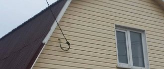
How to bring “earth” into the house
When using a steel strip, there are two options - bring a tire or wire into the house. I really don’t want to pull a steel tire measuring 24*4 mm - it looks unaesthetic. If there is, you can use the same bolted connection to install a copper busbar. It needs a much smaller size, it looks better (photo on the left).
You can also make a transition from a metal bus to a copper wire (cross section 10 mm2). In this case, two bolts are welded to the tire at a distance of several centimeters from each other (5-10 cm). The copper wire is twisted around both bolts, pressing them with a washer and nut to the metal (tighten as best as possible). This method is the most economical and convenient. It doesn't require as much money as using only copper/aluminum wire, and it's easier to run it through the wall than a busbar (even a copper one).
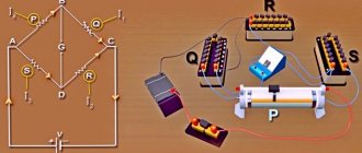
Grounding schemes: which one is better to make?
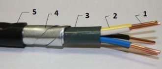
Currently, in the private sector, only two grounding connection schemes are used - TN-CS and TT. For the most part, a two-core (220 V) or four-core (380 V) cable (TN-C system) is suitable for the house. With such wiring, in addition to the phase (phase) wire, there is a protective conductor PEN, in which neutral and ground are combined. At the moment, this method does not provide adequate protection against electric shock, so it is recommended to replace the old two-wire wiring with a three-wire (220 V) or five-wire (380 V).
Two schemes that are used if you need to make grounding in a private house
In order to obtain normal three- or five-wire wiring, it is necessary to separate this conductor into ground PE and neutral N (in this case, an individual ground loop is required). This is done in the entrance cabinet on the facade of the house or in the accounting and distribution cabinet inside the house, but always before the meter. Depending on the separation method, either a TN-CS or TT system is obtained.
Installation of a TN-CS grounding system in a private house
When using this circuit, it is very important to make a good individual ground loop. Please note that with the TN-CS system, protection against electric shock requires the installation of RCDs and breakers. Without them there is no talk of any protection.
Also, to ensure protection, it is necessary to connect all systems that are made of conductive materials - heating, water supply, foundation reinforcement frame, sewerage, gas pipeline (if they are made of metal pipes) to the earth bus with separate wires (inextricable). Therefore, the grounding bus must be taken “with a reserve”.
Scheme for converting the TN-C system to TN-C-S
To separate the PEN conductor and create grounding in a private house TN-CS, three buses are needed: on a metal base - this will be a PE (ground) bus, and on a dielectric base - this will be an N (neutral) bus, and a small splitter bus for four " seating places.
The metal “ground” bus must be attached to the metal body of the cabinet so that there is good electrical contact. To do this, at the fastening points, under the bolts, the paint is removed from the body to bare metal. The zero bus - on a dielectric base - is best mounted on a DIN rail. This installation method fulfills the basic requirement - after separation, the PE and N buses should not intersect anywhere (should not have contact).
Grounding in a private house - transition from the TN-C system to TN-C-S
Next we connect like this:
- The PEN conductor coming from the line is connected to the bus splitter.
- We connect the wire from the ground loop to the same bus.
- From one socket with a copper wire with a cross-section of 10 mm 2 we place a jumper on the ground bus;
- From the last free socket we place a jumper on the zero bus or neutral bus (also a 10 mm 2 copper wire).
Now that's it - grounding in a private house is done according to the TN-CS scheme. Next, to connect consumers, we take the phase from the input cable, zero from the N bus, and ground from the PE bus. We make sure that ground and zero do not intersect anywhere.
Grounding according to the TT system
Converting a TN-C circuit to TT is generally simple. There are two wires coming from the pole. The phase conductor is further used as a phase, and the protective PEN conductor is attached to the “zero” bus and is then considered zero. The conductor from the made circuit is directly supplied to the grounding bus.
Do-it-yourself grounding in a private house - TT diagram
The disadvantage of this system is that it provides protection only for equipment that requires the use of an “earth” wire. If there are also household appliances made using a two-wire circuit, they may be energized. Even if the housings are grounded with separate conductors, in case of problems, the voltage may remain at “zero” (the phase will be broken by the machine). Therefore, of these two schemes, TN-CS is preferred as it is more reliable.
How to properly connect a wire in a junction box
The most controversial and painful problem during electrical installation work is the connection of wires and cables in the junction box. Electricians weld, sleeve (crimp), solder, use various clamps (pads, clamps, terminals, PPE - connecting insulating clamps), twist. How many electricians, so many different opinions.
What do the rules for connecting wires and cables say?
We will use several sources that are relevant today. PUE-7 (Rules for electrical installations), SNiP 3.05.06-85 (Electrical devices), GOST R 50571.5.52-2011. (Low-voltage electrical installations).
PUE-7 Chapter 2.1
Section: Electrical wiring
2.1.21. Connection, branching and termination of wire and cable cores must be carried out using crimping, welding, soldering or clamping (screw, bolt, etc.) in accordance with current instructions approved in the prescribed manner.
2.1.22. At the points of connection, branching and connection of wire or cable cores, a supply of wire (cable) must be provided, ensuring the possibility of re-connection, branching or connection.
SNiP 3.05.06-85
Electrical installation work
Section: Electrical wiring
3.34. All connections and branches of installation wires must be made by welding, crimping in sleeves or using clamps in branch boxes.
Metal branch boxes where wires enter them must have bushings made of insulating materials. It is allowed to use pieces of polyvinyl chloride tube instead of bushings. In dry rooms, it is allowed to place wire branches in sockets and niches of walls and ceilings, as well as in ceiling voids. The walls of the sockets and niches must be smooth, the branches of the wires located in the sockets and niches must be covered with covers made of fireproof material.
GOST R 50571.5.52-2011.
526 Electrical connections
526.2 When choosing means of connection, the following should be considered:
— conductor material and its insulation;
- the number and shape of wires forming the conductor;
- cross-sectional area of the conductor;
- the number of conductors that will be connected together.
Notes:
1 The use of solder connections is recommended to be avoided, except for communication circuits. If such connections are used, they must be made taking into account possible displacements, mechanical forces and temperature increases due to short circuits.
Expanded comment
We have reviewed all regulations governing the connection of wires. Let's look at the advantages and disadvantages.
Crimping (sleeving)
All standards recommend
Very high quality connection, large contact area. There is perhaps only one drawback: the sleeve is large in size and you have to make large distribution boxes, which affects the design of the room.
Sleeve, twist and terminal Vago
Photo and brief description
On the left in the photo is a connection made using a sleeve. The wires are inserted into a tinned sleeve and crimped with a special press. If the sleeve is chosen correctly, the connection turns out to be very good. There is a twist in the center, if done as in the photo it will be no worse than the sleeve, but it is prohibited by the rules, we do not use it in our work. On the right is an attempt to repair the wiring with the help of Vaga, the connection got hot, the terminal melted, and it’s not far from a fire.
Welding
All standards recommend
Good contact, small dimensions. The disadvantage is that it is problematic to weld the connection of a large number of wires without damaging the insulation (very strong heating).
Soldering
It prescribes the use of only PUE, SNiP is silent, and GOST generally recommends avoiding connections using soldering.
It is quite difficult to properly solder even two wires, but if successful, the connection will be of high quality. It is practically impossible to solder five, six or more wires, especially under the ceiling or in a hard-to-reach place where most customers ask to put a junction box so that it is not an eyesore.
Twist
Although no one has come up with a better idea yet. The wires are always twisted first, and then boiled, soldered, or crimped. I will not agitate, we will follow the rules, twisting in its pure form is PROHIBITED!
PPE, Vago terminal and screw clamp
Photo and brief description
On the left in the photo is a connection made using PPE. The wires are first twisted, which in itself is not bad, and the cap is screwed on top in full accordance with the rules. In the center of Vaga (with hoisting flags is considered the best option), it worked under load for about two years, melted plastic and insulation. On the right is a screw clamp, the problem is the same as with Vaga, the connection gets hot, the consequences are unpredictable
Squeezes
All standards recommend
There are a lot of different wire clamps, all of them are certified, but, unfortunately, they have different quality.
The most common Wago terminals: installation is quick, looks beautiful, but cannot withstand long-term loads close to the maximum. Ours only in the case of work on an agreed project, where the model of connecting terminals is clearly stated. Thus, we relieve ourselves of responsibility in the event of an emergency, shifting it to the designer and manufacturer of the terminals.
Screw clamps: A high-quality connection is obtained only with clamps where there is an additional blade under the screw, and if the screw is screwed directly into the wire, expect it to burn over time.
PPE (Connecting Insulating Clamp): When used in its pure form, the problem is the same as with welding and soldering, clamping a large number of wires. But if we first twist it, twenty to twenty-five millimeters, and then twist the PPE on top, the result is excellent. The connection is not subject to heating, which has a positive effect on further operation. We have been using this method for more than fifteen years and have not had a single complaint. There is only one drawback: a bare neck sticks out from under the PPE, which needs to be further insulated. Therefore, the method is not as aesthetic as; “Wago” terminals, but the connection is very good, the contact area significantly exceeds the cross-section of the conductor.