What is the efficiency of a transformer and what does it depend on?
Efficiency (the full interpretation of this abbreviation) is the ratio of useful electricity to that supplied to the device.
In addition to energy, the efficiency indicator can be determined by calculation based on power indicators based on the ratio of the useful value to the total value. This characteristic is very important when choosing a device and determines the effectiveness of its use.
The magnitude of the efficiency depends on the energy losses that are allowed during the operation of the device. These losses are of the following types:
- electrical - in the conductors of the coils;
- magnetic - in the core material.
The magnitude of these losses when designing a device depends on the following factors:
- overall dimensions of the device and shape of the magnetic system;
- compactness of the coils;
- density of assembled sets of plates in the core;
- diameter of wire in coils.
Reducing losses in the unit is achieved during the design process of the device, using soft magnetic ferromagnetic materials for the manufacture of the core. Electrical steel is assembled into thin plates, insulated relative to each other by a special layer of applied varnish.
During operation, the efficiency of the device is determined by:
- applied load;
- dielectric medium - a substance used as a dielectric;
- uniformity of load supply;
- oil temperature in the unit;
- degree of heating of the coils and core.
If during operation the unit is constantly underloaded or the specified operating conditions are violated, in addition to the risk of failure, this leads to a decrease in the efficiency of the device.
A transformer, unlike electrical machines, practically does not allow mechanical energy losses, since it does not include moving components. Insignificant energy consumption occurs due to the temperature heating of the device.
Dependence of transformer efficiency on load
To plot the graph ή =f ( β ) with сosφ2 = 1.0 and сosφ2 = 0.8, determine the efficiency of the transformer for a number of values of the load factor β equal to 0.25; 0.5; 0.75; 1.0 and 1.2, using the expression
| ή = Р2 /Р1 = Р2 / ( Р2 + Р + β 2 Рк ) | (30) |
| ή = 1 - (P0 nom + β 2 Pk nom) / (β Snom cosφ2 + P0 nom + β 2 Pk nom) | (32) |
where Snom is the rated power of the transformer, VA.
Based on the calculation results, efficiency graphs are constructed (Fig. 6).
The maximum value of the transformer efficiency corresponds to the load at which the electrical losses of the transformer are equal to the magnetic losses. The load factor corresponding to the maximum efficiency value is calculated using formula (28)
The value β is marked on the abscissa axis and, by drawing an ordinate at this point, the maximum efficiency values are determined. These values can be obtained from (31) by substituting β into this expression:
| ήmax = 1 - P0 nom / (0.5 Snom cosφ2 + P0 nom) | (32) |
Work order
5.1. Based on the passport and calculated data, fill out table1
| Passport details | Calculated and determined | ||||||||
| Snom, VA | f, Hz | U1nom, V | U2nom, V | I1nom, A | I2nom, A | i, % | Ukz, % | ΔРst, W | ΔРм, W |
The values of I1nom and I2nom are calculated using the formula Inom = (they are necessary when conducting a short-circuit experiment), the values of Ukz, ΔРst, and ΔРм are entered into the table based on the experimental results.
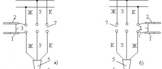
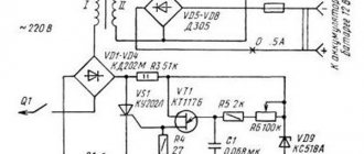
5.2. Conduct experiment XX.
To do this, in accordance with the circuit diagram in Fig. 7a, assemble an electrical circuit for conducting the experiment according to the wiring diagram in Fig. 7b. The circuit is powered from an regulated single-phase voltage source. Measurements of I10, U10, P are carried out using the K505 measuring kit, and voltage U20 is carried out with a digital voltmeter. Make at least five measurements at approximately equal intervals of the no-load current, changing the voltage supplied to the transformer from 0.5 U1nom to 1.15 U1nom. Enter the readings of measuring instruments in the table. 2.
| No. | Measurements | Computations | |||||||
| U10, V | I10, A | P, W | U20, V | Zm, Ohm | Rm, Ohm | Xm, Ohm | i, % | cosφ | K |
Calculations are carried out using formulas 14-18.
5.3. Conduct a short circuit experiment.
To do this, in the XX experiment circuit, replace the voltmeter in the secondary winding with an ammeter according to the electrical circuit diagram in Fig. 8. Use an ammeter with a measurement limit of 1A on the vertical part of the stand. Using LATR, increase the voltage from 0 to a value at which the current in the primary winding reaches the rated value (I1k = I1nom).
Enter the readings of measuring instruments in the table. 3.
| No. | Measurements | Computations | ||||||||
| U1k, V | I1k, A | I2k, A | Pk, W | Uk, % | Zк, Ohm | Rк, Ohm | Xk, Ohm | cosφк | R1, Ohm | X1, Ohm |
Calculations are carried out using formulas 21-24, 27.
5.4. Conduct a transformer load experiment by assembling a circuit according to Fig. 9
As a load, connect resistors with variable and constant parameters to the terminals of the secondary winding, the total resistance of which is calculated taking into account that the current in the secondary winding should vary from I2 = 0.1 I2nom to I2 = (1.2…1.25) I2nom ; U1 = U1nom = const. In this case, сosφ2 = 1. By changing the load resistance, carry out 5-6 measurements.
To change cosφ2, use an inductor as a load (cosφ2 = 0.8).
Enter the readings of measuring instruments in the table. 4.
| No. | Measurements | Computations | |||||||||
| U1н, V | I1, A | P1, W | U2, V | I2, A | сosφ1 | η | P2, W | ΔU2, % experience | ΔU2, % calculation | β | сosφ2 |
Calculations are carried out using the formulas:
Based on these data, construct the external characteristics U2 = f (β) and the dependences η = f (β)
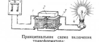
Description and principle of operation of the transformer
A transformer is a device used to lower or increase voltage, change the number of phases and, in rare cases, change the frequency of alternating current.
The following device types exist:
- power;
- measuring;
- low power;
- pulse;
- peak transformers.
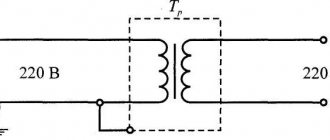
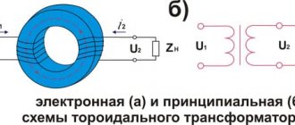
A static device consists of the following main structural elements: two (or more) windings and a magnetic circuit, which is also called a core. In transformers, voltage is supplied to the primary winding and removed from the secondary in a converted form. The windings are connected inductively by a magnetic field in the core.
Along with other converters, transformers have a coefficient of performance (abbreviated as efficiency), with the symbol . This coefficient represents the ratio of energy effectively used to energy consumed from the system. It can also be expressed as the ratio of the power consumed by the load to the power consumed by the device from the network. Efficiency is one of the primary parameters characterizing the efficiency of the work performed by a transformer.
Power factor improvement
The power factor value is calculated when designing networks. Since its low value is a consequence of an increase in the amount of total electricity losses. To increase it, networks use various correction methods, increasing its value to 1.
Increasing cos φ has 3 main objectives:
- reduction of electricity losses;
- rational use of non-ferrous metals to create electrically conductive equipment;
- optimal use of the installed power of transformers, generators and other alternating current machines.
Technically, correction is implemented in the form of introducing various additional circuits to the device input. This technique is required for uniform use of phase power, eliminating overloads of the neutral wire of a 3-phase network, and is mandatory for switching power supplies with an installed power of 100 W or more.
In addition, compensation makes it possible to ensure that there are no surges in the consumed current at the peak of the sinusoid, and that the load on the supply line is uniform.
Different types of transformers and their ratios
Although the converters are not much different from each other structurally, their purpose is quite broad. There are the following types of transformers, in addition to those discussed:
A feature of the autotransformer is the absence of galvanic isolation; the primary and secondary windings are made of one wire, and the secondary is part of the primary. Pulse scales short pulsed square wave signals. The welding machine operates in short circuit mode. Separators are used where special safety in electrical engineering is needed: wet rooms, rooms with a large number of metal products, etc. Their k is basically 1.
The peak transformer converts sinusoidal voltage into pulse voltage. A dual choke is two double coils, but according to its design features it is classified as a transformer. The transfluxor contains a core made of a magnetic circuit with a high residual magnetization, which allows it to be used as a memory. Rotator transmits signals to rotating objects.
Air and oil transformers differ in the method of cooling. Oil-based ones are used for scaling high power. Three-phase are used in a three-phase circuit.
More detailed information can be found about the current transformer transformation ratio in the table.
| Rated secondary load, V | 3 | 5 | 10 | 15 | 20 | 30 | 40 | 50 | 60 | 75 | 100 |
| Coefficient, n | Nominal limiting factor | ||||||||||
| 3000/5 | 37 | 31 | 25 | 20 | 17 | 13 | 11 | 9 | 8 | 6 | 5 |
| 4000/5 | 38 | 32 | 26 | 22 | 20 | 15 | 13 | 11 | 10 | 8 | 6 |
| 5000/5 | 38 | 29 | 25 | 22 | 20 | 16 | 14 | 12 | 11 | 10 | 8 |
| 6000/5 | 39 | 28 | 25 | 22 | 20 | 16 | 15 | 13 | 12 | 10 | 8 |
| 8000/5 | 38 | 21 | 20 | 19 | 18 | 14 | 14 | 13 | 12 | 11 | 9 |
| 10000/5 | 37 | 16 | 15 | 15 | 14 | 12 | 12 | 12 | 11 | 10 | 9 |
| 12000/5 | 39 | 20 | 19 | 18 | 18 | 12 | 15 | 14 | 13 | 12 | 11 |
| 14000/5 | 38 | 15 | 15 | 14 | 14 | 12 | 13 | 12 | 12 | 11 | 10 |
| 16000/5 | 36 | 15 | 14 | 13 | 13 | 12 | 10 | 10 | 10 | 9 | 9 |
| 18000/5 | 41 | 16 | 16 | 15 | 15 | 12 | 14 | 14 | 13 | 12 | 12 |
Almost all of the devices listed have a core for transmitting magnetic flux. The flux appears due to the movement of electrons in each of the turns of the winding, and the current strengths should not be equal to zero. The current transformation ratio also depends on the type of core:
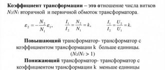
The transformation ratio of transformers is the ratio of the voltage of the high-voltage (HV) winding to the voltage of the low-voltage (LV) winding at no-load:
Where: Kl - linear voltage transformation ratio;
U1 - linear voltage of the HV winding;
U2 is the linear voltage of the LV winding.
When determining the transformation ratio of homogeneous transformers or the phase transformation ratio of three-phase
transformers, the voltage ratio can be equated to the ratio of the number of turns of the winding
where: Kf - phase transformation ratio;
U1ph, U2ph - phase voltages of the HV and LV windings, respectively;
When measuring the linear transformation ratio of a three-phase transformer, the equality of the ratio of the highest and lowest linear voltages of the windings and, accordingly, the number of HV and LV turns is maintained only if the connection groups of these windings are the same.
If the primary and secondary windings are connected in the same way, for example, both in a star, both in a triangle, and so on, the phase and linear transformation ratios are equal to each other. With different winding connection schemes, for example, one in a star and the other in a triangle, the linear and phase transformation ratios are not the same (in this case they differ from each other by 3 times).
The transformation ratio is determined on all branches of the windings and for all phases. These measurements, in addition to checking the transformation ratio itself, also make it possible to check the correct installation of the voltage switch at the appropriate stages, as well as the integrity of the windings.
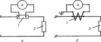
To determine the transformation ratio, the method of two voltmeters is used (Fig. 2)
Fig.2 Determination of transformation ratio.
From the high voltage side (HV), a three-phase voltage of 220 V is supplied and the voltage on the secondary winding is measured.
Attention! Voltage is supplied only to the HV windings (A, B, C). The measurement results are entered into table 2
Voltmeter measurement limits: PV1-250 V,PV2-15V
The measurement results are entered into table 2. Voltmeter measurement limits: PV1-250 V, PV2-15V.
Note: In this work, the transformer has one switch position.
The transformation coefficient of individual phases measured on the same branches should not differ from each other by more than 2%.
Methods for determining efficiency
Transformer efficiency can be calculated using several methods. This value depends on the total power of the device, increasing with the increase in the specified indicator. The efficiency value ranges from 0.8 to 0.92 at power values from 10 to 300 kW.
Knowing the value of the maximum power, you can determine the efficiency value using special tables.
Direct measurement
The formula for calculating this indicator can be presented in several expressions:
ɳ = (Р2/Р1)х100% = (Р1 – ΔР)/Р1х100% = 1 – ΔР/Р1х100%,
wherein:
- ɳ – efficiency value;
- P2 and P1 – respectively the value of useful and consumed network power;
- ΔР – the value of the total power losses.
From this formula it is clear that the value of the efficiency indicator cannot exceed one.
After a step-by-step transformation of the above formula, taking into account the use of the values of electric current, voltage and angle between the phases, the following relationship is obtained:
ɳ = U2хI2хcosφ2/ U2хI2хcosφ2 + Robm + Рс,
wherein:
- U2 and I2 – respectively, the value of voltage and current in the secondary winding;
- Robm and Rs - the amount of losses in the windings and core.
The presented formula is contained in GOST, which describes the definition of this indicator.
Efficiency calculations
Determination by indirect method
For devices with high operating efficiency, with an efficiency value exceeding 0.96, accurate calculation is not always possible. Therefore, this value is determined using an indirect method, which involves assessing the power indicators in the primary coil, the secondary coil and the allowed losses.
Assessing the characteristics of the transformer, it should be noted the high efficiency of using this equipment, due to its design features.
Types of losses in a transformer
The process of transferring electricity from the primary winding to the secondary is accompanied by losses. For this reason, not all energy is transferred, but most of it.
The design of the device does not include rotating parts, unlike other electric machines. This explains the absence of mechanical losses in it.
So, the device contains the following losses:
- electrical, in copper windings;
- magnetic, in steel core.
Energy diagram and the Law of Conservation of Energy
The principle of operation of the device can be schematically represented in the form of an energy diagram, as shown in Image 1. The diagram reflects the process of energy transfer, during which electrical and magnetic losses are generated.
According to the diagram, the formula for determining the effective power P2 is as follows:
P2=P1-ΔPel1-ΔPel2-ΔPm (1)
where, P2 is useful, and P1 is the power consumed by the device from the network.
Denoting the total losses ΔP, the law of conservation of energy will look like: P1=ΔP+P2 (2)
From this formula it is clear that P1 is spent on P2, as well as on the total losses ΔP. Hence, the efficiency of the transformer is obtained in the form of the ratio of the supplied (useful) power to the consumed power (the ratio of P2 and P1).
How to calculate a power transformer using formulas in 5 steps
I present a simplified method that I have been using for several decades to create and test homemade transformer devices made from iron of an unknown brand in terms of load power.
Using it, I almost always managed to wind the circuit on the first try. Very rarely it was necessary to add or reduce a certain number of turns.
Stage No. 1. How does the power of a dry-type transformer affect the shape and cross-section of the magnetic circuit?
The calculation is based on the average efficiency ratio ŋ, as the ratio of the electrical power S2 converted in the secondary winding to the applied total power S1 in the primary.
Power losses in the secondary winding are estimated using a statistical table.
| Transformer power, watts | Efficiency ŋ |
| 15÷50 | 0,50÷0,80 |
| 50÷150 | 0,80÷0,90 |
| 150÷300 | 0,90÷0,93 |
| 300÷1000 | 0,93÷0,95 |
| >1000 | 0.95÷0,98 |
The electrical power of the device is determined by the product of the rated current flowing through the primary winding in amperes and the household wiring voltage in volts.
It is converted into magnetic energy flowing through the core, fully distributed in it depending on the shape of the flow distribution:
- for a ring figure of U-shaped plates, the cross-sectional area under the magnetic circuit coil is calculated as Qc=√S1;
- for a core made of Ш-shaped plates Qc=0.7√S1.
Thus, the first stage of the calculation allows: knowing the required amount of primary or secondary power, select a magnetic core according to the shape and cross-section of the core; or, based on the dimensions of the existing magnetic core, estimate the electrical power that the designed transformer can transmit.
Stage No. 2. Features of calculating the transformation ratio and currents inside the windings
A power transformer is created to convert electrical energy from one voltage value to another, for example, U1=220 volts at the input and U2=24 V at the output.
The transformation ratio in the above example is written as the expression 220/24 or a fraction with the primary voltage value in the numerator and the secondary voltage in the denominator. It also allows you to determine the ratio of the number of turns between the windings.
At the first stage, we have already determined the electrical power of each winding. Using them and the voltage value, it is necessary to calculate the strength of the electric current I=S/U inside any coil.
Stage No. 3. How to calculate the diameters of copper wire for each winding
When determining the cross-section of the coil conductor, an empirical expression is used, taking into account that the current density lies in the range of 1.8÷3 amperes per square millimeter.
We determined the current value in amperes for each winding in the previous step.
Now we simply take the square root of it and multiply by a factor of 0.8. We write the resulting number in millimeters. This is the estimated wire diameter for the coil.
It is selected taking into account the release of permissible heat due to the current flowing through it. If space in the core window allows, the diameter can be slightly increased. Then these windings will be better adapted to thermal loads.
When, even with tight winding, all the turns of the wire do not fit into the window of the magnetic circuit, then its cross-section can be slightly reduced. But, such a transformer should be used for short-term operation and subsequent cooling.
When choosing the diameter of the wire, an optimal ratio is achieved between its heating during operation and the dimensions of the free space inside the core, allowing all the windings to be placed.
Stage No. 4. Determining the number of turns of windings according to the characteristics of electrical steel: important points
The calculation is based on the magnetic properties of the iron core. Industrial transformers are assembled from different types of electrical steel, selected for specific operating conditions. They are calculated using complex, individual algorithms.
The home handyman gets magnetic cores of an unknown brand, the electrical characteristics of which are practically impossible for him to determine. Therefore, the formulas take into account average parameters, which are not difficult to adjust during setup.
For the calculation, an empirical coefficient ω' is introduced. It takes into account the magnitude of the voltage in volts, which is induced in one turn of the coil and is associated with the cross-section of the magnetic circuit Qc (cm kV).
In the primary winding, we calculate the number of turns as W1= ω'∙U1, and in the secondary - W2= ω'∙U2.
Stage No. 5. Taking into account the free space inside the magnetic circuit window
At this step, you need to estimate whether all the windings will fit into the free space of the core window, taking into account the dimensions of the coil.
To do this, we assume that the wire does not have a round cross-section, but a square with a side of the same diameter. Then, with absolutely ideal dense packing, it will occupy an area equal to the product of the unit section and the number of turns.
We increase this area by 30 percent, because it will not be possible to wind the turns perfectly this way. This will be a place inside the cavities of the coil, and it will still take up a certain space.
Next, we compare the resulting areas for the coils of each winding with the window of the magnetic circuit and draw conclusions.
The second way to evaluate is to wind the coils “for luck.” It can be used if the new design is rewound with wire from old working coils on the same core.
Power calculation formula
Simplified calculation of a power transformer.
By finding an open area or disassembling the device, you can measure the thickness of the central lobe. Abstractly, let's take this parameter equal to two centimeters. It is worth recalling that when roughly calculating power, measurements should be taken as accurately as possible. Next, you need to multiply the size of the magnetic circuit set, equal to three centimeters, and the thickness of the plate petal, equal to two centimeters. As a result, we get a cross-section of the magnetic circuit of six square centimeters. To make further calculations, you need to familiarize yourself with a formula such as S=1.3*√Ptr, where:
- S is the cross-sectional area of the magnetic circuit.
- Ptr is the power of the transformer.
- The coefficient 1.3 is an average value.
Recalling the formulas from the mathematics course, we can conclude that in order to calculate the power, we can make the following transformation:
The next step is to substitute into this formula the resulting value of the magnetic circuit cross-section of 6 square centimeters, as a result we obtain the following value:
After all the calculations, we get an abstract value of 20.35 watts, which will be difficult to find in transformers with an W-shaped core. Real values fluctuate around seven watts. This power will be quite enough to assemble a power supply for equipment operating at audio frequencies and having a power ranging from 3 to 5 watts.
General information about transformers
A transformer is an electromagnetic device that converts alternating current with a change in voltage value. The operating principle of the device involves the use of electromagnetic induction.
The device consists of the following main elements:
- primary and secondary windings;
- the core around which the windings are wound.
Principle of operation of a transformer
Changing characteristics is achieved due to different numbers of turns in the windings at the input and output.
The current in the output coil is excited by the creation of magnetic flux when voltage is applied to the input contacts.
What is the formula for voltage regulation?
Load regulation (percentage) = 100 x (no load voltage - full load voltage) divided by full load voltage
. … Linear regulation is the amount of change in voltage at the output of a voltage regulator or transformer that results from a change in voltage at the input of the voltage regulator or transformer.
Interesting materials:
What is an index in basketball statistics? What is the VTM 4 indicator on a Honda Pilot? What is the smartphone industry? What are initials in grammar? What is synchronization? What is a SolidWorks inspection? What is Instagram and how do you use it? What is the Sharpen Tool in Photoshop? What is the Artboard tool in Illustrator? What is a firmware flashing tool?
Determination of efficiency
With the required accuracy for calculating the device, the previously derived efficiency values can be taken from Table No. 1:
| Total power, W | Efficiency |
| 10-20 | 0,8 |
| 20-40 | 0,85 |
| 40-100 | 0,88 |
| 100-300 | 0,92 |
As shown in the table, the value of the parameter directly depends on the total power.
Determination of efficiency by direct measurements
The formula for calculating efficiency can be presented in several versions:
(3)
This expression clearly reflects that the efficiency value of the transformer is not more than one, and is also not equal to it.
The following expression determines the net power value:
P2=U2*J2*cosφ2, (4)
where U2 and J2 are the secondary load voltage and current, and cosφ2 is the power factor, the value of which depends on the type of load.
Since P1=ΔP+P2, formula (3) takes on the following form:
(5)
Electrical losses of the primary winding ΔPel1n depend on the square of the current flowing in it. Therefore, they should be defined this way:
(6)
In its turn:
(7)
where rmp is the active winding resistance.
Since the operation of an electromagnetic device is not limited to the nominal mode, determining the degree of current load requires the use of a load factor, which is equal to:
β=J2/J2н, (8)
where J2н is the rated current of the secondary winding.
From here, we write down expressions for determining the secondary winding current:
J2=β*J2н(9)
If we substitute this equality into formula (5), we get the following expression:
(10)
Note that determining the efficiency value using the last expression is recommended by GOST.
Summarizing the information presented, we note that the efficiency of a transformer can be determined by the power values of the primary and secondary windings of the device at rated mode.
Power, efficiency, and power factor of the transformer
Rated power.
The rated power of a transformer is the power that it can deliver for a long time without overheating above the permissible temperature.
The normal service life of a power transformer should be at least 20 years. Since the heating of the windings depends on the amount of current flowing through them, the transformer passport always indicates the total power Snom in volt-amperes or kilovolt-amperes. Depending on the power factor cosφ2 at which consumers operate, more or less useful power can be obtained from the transformer. When cosφ2 = l, the power of consumers connected to it can be equal to its rated power Snom. At cosφ2.
Power factor.
The power factor cosφ of a transformer is determined by the nature of the load connected to its secondary circuit. As the load decreases, the inductive reactance of the transformer windings begins to have a strong effect and its power factor decreases. When there is no load (at no load), the transformer has a very low power factor, which degrades the performance of AC sources and electrical networks. In this case, the transformer must be disconnected from the AC mains.
Power losses and efficiency.
When transferring power from the primary winding of a transformer to the secondary, power losses occur both in the wires of the primary and secondary windings (electrical losses and or copper losses) and in the steel of the magnetic core (steel losses).
When idling, the transformer does not transmit electrical energy to the consumer. The power it consumes is spent mainly on compensating for power losses in the magnetic circuit from the action of eddy currents and hysteresis. These losses are called steel losses or no-load losses. The smaller the cross-section of the magnetic circuit, the greater the induction in it, and therefore the no-load losses. They also increase significantly when the voltage supplied to the primary winding increases above the nominal value. When operating powerful transformers, no-load losses amount to 0.3-0.5% of its rated power. Nevertheless, they strive to reduce them as much as possible. This is explained by the fact that steel losses do not depend on whether the transformer is running idle or under load. And since the total operating time of the transformer is usually quite long, the total annual energy losses during no-load operation are significant.
When under load, electrical losses in the winding wires (copper losses), proportional to the square of the load current, are added to the no-load losses. These losses at rated current are approximately equal to the power consumed by the transformer during a short circuit when voltage Uk is applied to its primary winding. For high-power transformers they are usually 0.5-2% of rated power. Reducing the total losses is achieved by appropriate selection of the cross-section of the wires of the transformer windings (reduction of electrical losses in the wires), the use of electrical steel for the manufacture of the magnetic core (reduction of losses from magnetization reversal) and delamination of the magnetic core into a number of sheets isolated from each other (reduction of losses from eddy currents).
The efficiency of the transformer is equal to
The efficiency of the transformer is relatively high and reaches 98-99% in high power transformers. In low-power transformers, efficiency can decrease to 50-70%. When the load changes, the efficiency of the transformer changes, as the useful power and electrical losses change. However, it remains of great importance over a fairly wide range of load changes (Fig. 119.6). With significant underloads, the efficiency decreases, since the useful power decreases, and the losses in steel remain unchanged. A decrease in efficiency is also caused by overloads, since electrical losses increase sharply (they are proportional to the square of the load current, while the useful power is only the current to the first power). The efficiency has its maximum value at a load when the electrical losses are equal to the losses in steel.
When designing transformers, they strive to ensure that the maximum efficiency value is achieved at a load of 50-75% of the rated load; this corresponds to the most probable average load of the operating transformer. This load is called economic.
Voltage drop and resistance of transformer windings
Relative active voltage drops in the primary and secondary windings of a single-phase transformer at rated load:
In the case of a three-phase transformer, the right-hand sides of these formulas must be divided by √3. Active resistance of the windings of a single-phase transformer:
In the case of a three-phase transformer, the right-hand sides of these formulas must be divided by 3 when connecting the windings with a star.
Active short circuit resistance of a two-winding transformer, reduced to the primary winding:
where U1 and U2 are taken from the task, I1 and I2 – from position 1, W1 and W2 – from position 4, Pm and Pm2 – from position 7.
Relative inductive voltage drops in individual windings of a two-winding transformer:
eS [%] = eS1 [%] + eS2 [%] .
Inductive short circuit resistance of a two-winding transformer, reduced to the primary winding:
Where
U1 and f are taken from the task; I1 and I2 – from position 1; E1, W1 and W2 – from position 4; δ1, δ2, δ12 and H – from position 6, lω1 and lω2 – from position 7.
Short circuit impedance of a two-winding transformer:
Short circuit voltage of two-winding transformer:
In the case of a three-phase transformer, you need to divide the right side of the expression for xк, and for ek [%] - multiply by √3.
The relative change in voltage of a two-winding transformer under load can be determined by the following approximate formula:
where cos φ2 is taken from the task, cos φ1 – from position 1.
Determination of efficiency by indirect method
Due to the large efficiency values, which can be equal to 96% or more, as well as the uneconomical nature of the direct measurement method, it is not possible to calculate the parameter with a high degree of accuracy. Therefore, its determination is usually carried out by an indirect method.
Summarizing all the obtained expressions, we obtain the following formula for calculating the efficiency:
η=(P2/P1)+ΔPm+ΔPel1+ΔPel2, (11)
To summarize, it should be noted that a high efficiency indicator indicates the efficient operation of the electromagnetic device. Losses in the windings and core steel, according to GOST, are determined by testing no-load or short circuit, and measures aimed at reducing them will help achieve the highest possible efficiency values, which is what we need to strive for.
Basic methods of cos φ correction
1. Correction of the reactive component of power is carried out by turning on a reactive element that has the opposite effect. For example, to compensate for the operation of an asynchronous machine with a high inductive reactive component of power, a capacitor is connected in parallel.
2. Correction of nonlinearity of power consumption . When the load's current consumption is disproportionate to the fundamental harmonic of the voltage, a passive (active) power factor corrector is introduced into the circuit to increase the power factor. The simplest example of a passive cos φ corrector is a high-inductance inductor connected in series with the load. The inductor smoothes out pulsed load consumption and creates the lowest, fundamental current harmonic.
3. Correction in a natural way , which does not involve the installation of additional devices, involves streamlining the technological process, rational distribution of loads, leading to an improvement in the electricity consumption of equipment and an increase in the power factor.
Detailed video explaining what cosφ is:
Calculation of transformer rated power
Rated power, MB • A, of a transformer at a substation with the number of transformers n > 1 in general form is determined from the expression
For network substations, where up to approximately 25% of low-critical consumers can be switched off in emergency mode, it is usually taken to be 0.75...0.85. In the absence of consumers of category III K 1-2 = 1 For production (consumers) of the 1st and special groups, design solutions are known that focus on 50% load of transformers.
Widespread use of warehouse and mobile reserve transformers is recommended, and in emergency conditions it is allowed to overload transformers by 40% for a maximum period of a total daily duration of no more than 6 hours for no more than 5 days.
In this case, the filling factor of the daily load schedule of kp transformers in conditions of its overload should be no more than 0.75, and the initial load factor kpn should be no more than 0.93.
Since K1-2 1 their ratio is K = K 1-2 / K per. is always less than one and characterizes the reserve power that is built into the transformer when choosing its rated power. The smaller this ratio is, the smaller the installed power reserve built into transformers will be and the more efficient the use of transformer power will be, taking into account overload.
An overestimation of the coefficient k leads to an overestimation of the total installed power of transformers at the substation.
Reducing the coefficient is possible only to such a value that, taking into account the overload capacity of the transformer and the possibility of disconnecting non-critical consumers, will allow the main load to be covered by one transformer remaining in operation in the event of an emergency failure of the second transformer.
Thus, for a two-transformer substation
Currently, there is a practice of choosing the rated power of a transformer for two transformer substations, taking into account the value k = 0.7, i.e.
Formally, expression (3.14) looks erroneous: indeed, the unit of active power is W; total (apparent) power - VA. There are also differences in the physical interpretation of S and P. But it should be understood that reactive power is compensated on the buses of the 5UR, ZUR substation and that the power factor cos f is in the range of 0.92... 0.95.
Then the error associated with simplifying expression (3.13) to (3.14) does not exceed the engineering error of 10%, which includes both the approximate value of 0.7 and the error in determining the fixed Рmax
Thus, the total installed capacity of a two-transformer substation.
With this value of k in emergency mode, the preservation of about 98% of Pmax is ensured without disconnecting non-critical consumers. However, taking into account the fundamentally high reliability of transformers, it can be considered quite acceptable to turn off some of the non-responsible consumers in rare emergency conditions.
With two or more transformers installed at a substation, in the event of an accident with one of the parallel operating transformers, the remaining transformers in operation take on its load. These emergency overloads do not depend on the previous operating mode of the transformer, are short-term and are used to ensure the passage of the maximum load.
The following are the values of short-term overloads of oil transformers with cooling systems M, D, DC, C in excess of the rated current (regardless of the duration of the previous load, ambient temperature and installation location).
Emergency overloads of oil transformers with all types of cooling:
For three-winding transformers and autotransformers, the indicated overloads refer to the most loaded winding.
Calculation of coefficient over time
The manufacturer determines the nominal load. In practice it is not uniform. During the day there are both underloads and overloads. In order not to make a mistake with the choice, equipment operation schedules are required for various periods (days, months, years). It is important to distribute the load so that insulation wear does not exceed the nominal value. Otherwise, the service life of the equipment will be shortened.
In summer, the average load should be lower than rated, in winter - the opposite. If several transformers operate in parallel, the total indicator is calculated. Regardless of the number of transformer equipment, the coefficient must be optimal.
At the moment, the problem of low load is relevant at two-transformer substations. You can increase the indicator if you use one converter. But in this case, if there is a breakdown or repair, consumers will be left without electricity.
When designing and reconstructing substations, situations are allowed in which one transformer operates with overload. When calculating equipment, the required power of the substation, the time of reloads and underloads are taken into account. In any situation, the overload factor cannot exceed 1.4.
The power of transformers should be such that they are loaded at 75-85% (average). Calculations are carried out on the basis of daily load schedules, which show the duration of underloads and overloads. At the same time, overload should not exceed 6 hours within 5 days.
Formulas
Transformer load factor formula:
β= t1/t2, where:
t1 – actual operating time under load;
t2 – nominal operating time under load.
This formula is used only in relation to a predetermined period of time (day, month, year).
Self-calculation of transformer power windings
Calculation of winding of a welding transformer.
Using books on radio engineering and electronics, we can independently calculate the winding and power of a transformer with a standard W-shaped core. In order to calculate the power of a device such as a transformer, it is necessary to correctly calculate the cross-section of the magnetic circuit. As for standard transformers with a W-shaped core, the cross-sectional size of the magnetic core will be measured by the length of the supplied plates, made of special electrical steel. So, in order to determine the cross-section of the magnetic circuit, it is necessary to multiply two indicators such as the thickness of the set of plates and the width of the central lobe of the W-shaped plate.
By taking a ruler, we can measure the width of the radiated transformer set. It is very important that it is best to carry out all measurements in centimeters, as well as calculations. This will eliminate errors in formulas and save you from unnecessary calculations when converting from centimeters to meters. So, figuratively, let’s take the width of the rows to be three centimeters.
Next you need to measure the width of its central petal. This task can become problematic, since many transformers can, due to their technological features, be covered with a plastic frame. In this case, you will not be able, without first seeing the real width, to make any calculations that will even closely resemble the real ones. In order to measure this parameter, you will need to look for places where this could be done. Otherwise, you can carefully disassemble its body and measure this parameter, but you should do this with pinpoint accuracy.
What to do if you purchased used equipment?
But if you have already used equipment and its functionality is unknown to you, you need to independently calculate the transformer winding and its power. But how to calculate the winding of a transformer and its power, at least approximately? It is worth noting that such a parameter as the power of the transformer is a very important indicator for this device, since it will determine how functional the device assembled from it will be. Most often it is used to create power supplies.
Calculation of powers of various transformers.
First of all, it should be noted that the power of a transformer depends on the current consumption and voltage that are necessary for its operation. In order to calculate the power, you need to multiply these two indicators: the current consumed and the supply voltage of the device. This formula is familiar to everyone from school, it looks like this:
Un - supply voltage, measured in volts, In - current consumption, measured in amperes, P - power consumption, measured in watts.
If you have a transformer that you would like to measure, you can do it right now using the following method. First, you need to inspect the transformer itself and determine its type and the cores used in it. When looking at a transformer, you need to understand what type of core is used in it. The W-shaped core type is considered the most common.
This core is used in not the best transformers in terms of efficiency, but you can easily find them on the shelves of electrical stores or unscrew them from old and faulty equipment. Availability and fairly low price make them quite popular among those who like to assemble the device with their own hands. You can also purchase a toroidal transformer, which is sometimes called a ring transformer. It is much more expensive than the first and has a better efficiency and other quality indicators, and is used in fairly powerful and high-tech devices.
Drill guide - what it is and how to use it.