This battery capacity tester allows you to measure the capacity of a battery or rechargeable battery (measurement in mAh or Ah) and discharge energy (in Wh).
The circuit is suitable for nickel-cadmium and nickel-metal hydride cells and batteries (1-12 cells), lead-acid (flooded, VRLA, SLA) batteries up to 12 V, lithium-ion and lithium-polymer (1-4 cells), and also for other types such as LiFePO4, NiZn, alkaline, etc., with a total voltage of up to 20 V.
A capacity tester will allow you to check, for example, the condition of the battery, the efficiency of the charging method, or detect counterfeit batteries (unfortunately, the market has been flooded with counterfeits in recent years).
This device also allows you to maintain the battery - discharge it to the required voltage before charging, or discharge the battery to the optimal voltage to prepare it for long-term storage.
Description
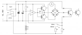
This battery capacity meter is based on an ATmega8A, ATmega8 or ATmega8L (DD1) microcontroller. The operating principle of the tester is simple: connect a fully charged battery to the device. After the battery has finished discharging, you will receive its capacity and energy values.
Silicone Soldering Mat
Size 55 x 38 cm, weight 800 g....
More details
The discharge current is digitally selectable from 0.01 to 2.56 A in 0.01 A increments. The discharge stops when the end voltage (cut-off voltage) is reached, which is also digitally selectable.
The Atmega8 microcontroller is synchronized by an internal RC oscillator with a frequency of 8 MHz. Since the accuracy of measurement depends on the accuracy of time measurement, therefore, the circuit uses an external quartz resonator at 32768 Hz.
The battery voltage (maximum value 20 V) is measured using a voltage divider across resistors with R10, R13, R16. Adjust the tuning resistor R16 so that the value on the display (in actual voltage display mode) is equal to the actual battery voltage.
The battery is discharged through transistor VT1 (IRLB8743). The discharge current is measured on shunt R19 (0.24 Ohm). The discharge current is stabilized by an operational amplifier (op-amp) DD2 MC33171. The reference voltage is obtained using pulse width modulation (PWM) from the OC1A pin (PB1 - pin 15) of the microcontroller.
The PWM signal passes through a voltage divider (R12, R14, R17) and a low-pass filter (C7), creating a constant voltage proportional to the desired discharge current. Next, the voltage at the gate of VT1 is controlled by the op-amp, so that the voltage at shunt R19 corresponds to this reference voltage.
Load fork, operating principle
Self-assembly of the device is not a task of increased complexity. Before assembly, you need to understand what the device is intended for and what it consists of.
Device
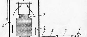
A load fork is a device with which it is possible to test a power source in a mode similar to its normal operating conditions. In most cases, when factory assembled, the device consists of a dial or electronic voltmeter, as well as one or two resistances for which metal spirals are installed. Measuring probes with terminals for connecting to the battery are attached to the ends of the spiral.
Sometimes an ammeter is installed in the load fork design. The device itself is presented in the form of a metal or plastic box with outgoing wires and clamps. Modern models are equipped with digital meters, liquid crystal displays, and also have several resistance coils with a switch for combining the load to the battery.
The device is used to check the voltage value on a power source with electrolytes based on acidic and alkaline compounds. When examining individual elements of cans, special forks with simplified characteristics are used. Using this device, it is possible to check the performance of not only the battery, but also any element of the electrical circuit. The measurements are carried out with the power connected, as well as with the electromotive force turned off. Not only the voltage can be controlled, but also all the necessary parameters, all depending on the complexity of the plug design.
Application of load fork
Using this device it is possible to perform the following actions:
- Determination of the storage time of the internal energy reserve. This parameter depends mainly on the internal capacity. Common models with a value of 50 A/h are able to maintain their parameters for 140 days under normal operating conditions. When the power source is connected to the network, the time is reduced by almost half. Most losses occur when the alarm system is working.
It is important to know! In winter, the battery discharges when the alarm is running on average within 15 days.
- Measurement of state of charge. In this case, the value of 11.7 V indicates that the battery is discharged. Full charge 12.7 V, half charge 12.3 V.
- Determination of possible charge retention time. When the reading on the load plug shows a value below 12 V, it indicates that it is necessary to restore the charge.
- Monitoring the short circuit between the plates in the battery. If there is a short circuit, the voltage drops to 9 V. When charging, the electrolyte boils.
- Determination of generator output parameters. Deviations from normal operation can lead to starting problems and battery failure.
- Monitoring the sulfation of electrode plates can be done if an ammeter is included in the package.
Difference between models
Load forks differ from each other in several ways:
- clarity in obtaining evidence;
- type of measuring device;
- resistance of resistors or spirals;
- Operating temperature range;
- measured voltage range;
- current ratings;
- different media of electrolytes used.
How to check correctly
The load plug is designed to test power supplies with a nominal power value of no higher than 12 W. However, it is possible to use increased power in the network if several resistors are used. To carry out an accurate check, the following procedure must be followed:
- measure the voltage at the terminals without load;
- the obtained value is compared with the passport data;
- when fully charged, connect the load;
- after 5 seconds, take voltmeter readings;
- A working battery should show a value of at least 9 V.
Calibration process
Set trimming resistor R18 to the central position. Connect a battery with a discharge current of at least 2.56 A and an ammeter in series. Set the desired discharge current to 2.56 A, start discharge (long press the SA1 button). Then set the trimming resistor R17 so that the actual discharge current is equal to the selected value (2.56 A).
Next, set the discharge current to 0.01A. Then adjust the bias of the DD2 op-amp inputs using R18 - set R18 so that the actual current is 0.01A.
Power transistor VT1 must be placed on a heatsink corresponding to the maximum required power dissipation during discharge (P = U*I). Transistor VT1 (IRLB8743) is a MOSFET with TTL logic that can operate at 5 V. If you are using a standard MOSFET type, then theoretically you can power the op amp from a higher voltage (this could be the voltage at the 7805 input), but I recommend logic MOSFET.
The HL1 LED indicates that discharge and measurement are in progress. Diodes VD1 and VD2 (1N4148) ensure complete blocking of transistor VT1 when the discharge process is not active.
To control the controller, use the SA1…SA3 buttons. A 4-digit LED display with a common anode is used as a display device. The display cathodes are connected to port D, the anodes are connected to bits 2-5 of port B. The display can be LD-D036UPG-C, LD-D028UR-C, LD-D036UR-C or LD-D056UR-C (very high brightness). The ultra-bright display eliminates the need for conventional transistors to amplify the anode current.
Display control is multiplex. The multiplexing frequency is about 100 Hz. Resistors R1 ... R8 determine the current of the display segments and, therefore, its brightness. They are selected so that the current does not exceed the maximum output current of the microcontroller pin (40 mA).
The battery capacity tester is powered by a power source with a voltage of 8 - 30V. The current consumption is about 15-45 mA, depending on the number of illuminated indicator segments and the resistance of resistors R1 ... R8. Capacitors C1, C2 and C3 should be located as close to the microcontroller as possible.
Connect an appropriate fuse in series with the battery being tested, otherwise tester failure (for example, current control failure or VT1 short circuit) or incorrect battery polarity may cause a fire! It is also recommended to use a fuse on the + input of the power supply.
A small modernization of the BT-168 battery tester or turning a loaf of bread into a trolleybus...
A big hello to everyone! This device has already been reviewed on MySKU (), so I’m not going to dwell on its features in detail. Instead, I will tell you how to perform minimal doping so that you can check not only one-and-a-half-volt, but also 3- and 12-volt elements. If anyone is interested, welcome to cat.
The operating principle of the device is to measure the battery voltage under load. I personally think this method is more revealing than checking with a conventional multimeter without a load and much less painful than checking the short-circuit current (albeit short-term).
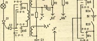
In the original diagram of the device, two circuits clearly appear: for one and a half volts (R1, R2) and for nine volts (R3, R4):
The heart of the tester is an analog voltmeter with an internal resistance of 280 Ohms and a measurement limit of 0.5 V. It is marked with a red dotted outline in the diagram. Please note that the internal resistance is indicated by a separate resistor in the diagram. This is done for clarity, because... Usually the resistance of the voltmeter is high enough and can be neglected, but not in our case.
The circuit for testing one and a half volt elements consists of two resistors: R1 (load resistor) and R2 (additional resistor, which, together with the internal resistance of the voltmeter, constitutes a simple voltage divider). The ratings are chosen so that at 1.5 V the load current will be 1.5/4 = 0.375 A (or 375 mA), and the voltage at the divider output (essentially on a voltmeter) will be equal to 1/3 of the measured one. The voltmeter scale is calibrated so that if the voltage under load sags to 66% or lower of the declared rating of the element, then it can be disposed of. That's all the "magic"
The situation is similar with a nine-volt circuit, only the load current here is different (9/215 = ~0.04 A or ~40 mA) and the additional resistor R4 is calculated cunningly, because with this connection, resistors R1 and R2 are connected as if in parallel to the internal resistance of the voltmeter, thereby reducing it to ~187 Ohms. The attentive reader will notice that when measuring one and a half volt elements, resistors R3 and R4 also “reduce” the internal resistance of the voltmeter, but in this case this has virtually no effect on the final result.
To be honest, I didn’t really like the fact that the resistors in both circuits introduce their “interference” into the measurements, so I got rid of this in the modified version.
Well, we seem to have figured out how the device works, now let’s move on directly to finishing it. When I first picked up this tester, I was at first delighted to find the ability to test “tablets”, but then I was disappointed, because... It turned out that, firstly, only 1.5-volt tablets can be tested, and secondly, testing them under a load of 375 mA is a mockery.
So I decided to adapt the device to also test three-volt and twelve-volt elements (and also share this brilliant idea with you!). To do this, we need a bunch of resistors (2 for each type of element) and two of the following:
This is a three-position slide switch with two groups (left) and a relay with one contact group (right). The switch was magically found in an old radio, and the relay was blatantly removed from the car alarm. Using a switch, we will set the type of elements being tested (by switching the necessary resistors), while the relay will operate exclusively when checking a nine-volt element, connecting the required circuit and disconnecting the unnecessary one. Despite the fact that the relay is designed for 12 volts, it also works clearly at 7-7.5 volts, which suits me quite well within the framework of this, so to speak, project.
Instead of a thousand words, let's just stick to the new scheme:
There seems to be nothing complicated here, SW is a switch, R1-R3 are load resistors, R4-R6 are additional resistors, the 1.5/3/12 test circuit contacts the voltmeter through a normally closed relay contact. The resistance of the relay winding is 400 Ohms, so I connected a 470 Ohm resistor in parallel to it, which in total gave a load of about the same 215 Ohms (216.09 Ohms, to be precise) as it was originally.
That, in fact, is all the parsley!
This is what the device looks like after modernization
Finally, a little about how to correctly calculate resistors. Load resistors are calculated using the formula Rн = U/I, where U is the rated voltage of the element (in volts), and I is the desired current in amperes.
For example, we want to test 12 V elements with a load of 50 mA (0.05 A), then Rн = 12/0.05 = 240 Ohm
Additional resistors are calculated a little more cunningly (for those interested, let them remember Ohm’s law and make up the proportion U1/R1 = U2/R2):
Rd = 2*(U-0.5)*280, where U is the rated voltage of the element
So, for example, for 12 V: Rd = 2*(12-0.5)*280 = 2*11.5*280 = 6440 Ohm ~= 6.4 kOhm
That's it now. Thank you for your attention! I tried to explain everything in detail, but if you suddenly have any questions, don’t hesitate to ask 
DIY load fork
Simple to make and inexpensive, the device will be useful in the garage of any car enthusiast. With the help of this device it will be possible to carry out continuous diagnostics of the power source, as well as the generator. If you do not have the necessary amount to purchase a load fork, you can make it yourself.
Material used
When making a fork, you may need the following materials:
- to measure voltage you will need a voltmeter, if we use an analog one, then it should have a measurement limit of up to 20 V;
- insulated wires up to 6 mm thick, designed for high current values;
- at the end of the wires you should use special powerful clamps made of chrome steel;
- frame made of non-flammable materials;
- holder made of rubberized steel.
Important! When making a homemade load plug, it is recommended to use wires and devices designed for maximum operating current values.
Scheme
Single Spiral Load Fork:
Load fork with two spirals:
where R is resistance in the form of spirals or a set of resistors;
S - switches or switches;
V - voltmeter device.
When measuring a battery with a capacity of up to 100 Ah, one resistance must be used; when testing a battery with an internal capacity above 100 Ah, two or more resistances are used.