When current flows through a homogeneous section of the circuit, the electric field does work. During the time Δt, a charge Δq = IΔt flows through the circuit. The electric field in a selected area does work
| ΔA = (φ1 – φ2)Δq = Δφ12IΔt = UIΔt, |
where U = Δφ12 – voltage. This work is called the work of electric current.
If both sides of the formula
| RI = U, |
expressing Ohm's law for a homogeneous section of a circuit with resistance R, multiply by IΔt, you get the relation
| RI 2 Δt = UIΔt = ΔA. |
This relationship expresses the law of conservation of energy for a homogeneous section of the chain.
The work ΔA of electric current I flowing through a stationary conductor with resistance R is converted into heat ΔQ released on the conductor.
| ΔQ = ΔA = RI 2 Δt. |
The law of converting the work of current into heat was established experimentally independently of each other by J. Joule and E. Lenz and is called the Joule–Lenz law.
The power of the electric current is equal to the ratio of the current work ΔA to the time interval Δt during which this work was performed:
The work of an electric current in SI is expressed in joules (J), power - in watts (W).
Let us now consider a complete direct current circuit, consisting of a source with an electromotive force and internal resistance r and an external homogeneous section with resistance R. Ohm's law for the complete circuit is written as
| (R + r)I = ε. |
By multiplying both sides of this formula by Δq = IΔt, we obtain a relationship expressing the law of conservation of energy for a complete DC circuit:
| RI 2 Δt + rI 2 Δt = IΔt = ΔAst. |
The first term on the left side ΔQ = RI 2 Δt is the heat released in the external section of the circuit during the time Δt, the second term ΔQist = rI 2 Δt is the heat released inside the source during the same time.
The expression IΔt is equal to the work of external forces ΔAst acting inside the source.
When electric current flows through a closed circuit, the work of external forces ΔAst is converted into heat released in the external circuit (ΔQ) and inside the source (ΔQist).
| ΔQ + ΔQist = ΔAst = IΔt |
It should be noted that this ratio does not include the work of the electric field. When current flows through a closed circuit, the electric field does not do any work; therefore, heat is produced only by external forces acting inside the source. The role of the electric field is reduced to the redistribution of heat between different sections of the circuit.
The external circuit can be not only a conductor with resistance R, but also some device that consumes power, for example, a DC motor. In this case, R must be understood as the equivalent load resistance . The energy released in the external circuit can be partially or completely converted not only into heat, but also into other types of energy, for example, into mechanical work performed by an electric motor. Therefore, the question of using the energy of a current source is of great practical importance.
Ohm's law for a closed circuit
A closed (complete) electrical circuit consists of a current source and resistance.
The current source has an emf (
) and resistance (r), which is called
internal
.
EMF ( electromotive force
) is the work of external forces to move a positive charge along a closed circuit (the physical meaning is similar to voltage, potential). The total resistance of the circuit is R+r.
1) Voltage at the source terminals, and accordingly in the external circuit
, where quantity is
the voltage drop
inside the current source.
2) If the external resistance of the closed circuit is zero, then this mode of the current source is called a short circuit.
1.11. Work and current power
When current flows through a homogeneous section of the circuit, the electric field does work. During the time Δt, a charge Δq = I Δt flows through the circuit. The electric field in a selected area does work
| ΔA = (φ1 – φ2) Δq = Δφ12 I Δt = UI Δt, |
where U = Δφ12 – voltage.
This work is called the work of electric current. If both sides of the formula
| RI = U, |
expressing Ohm's law for a homogeneous section of a circuit with resistance R, multiply by IΔt, you get the relation
| R I2 Δt = UI Δt = ΔA. |
This relationship expresses the law of conservation of energy for a homogeneous section of the chain.
The work ΔA of electric current I flowing through a stationary conductor with resistance R is converted into heat ΔQ released on the conductor.
| ΔQ = ΔA = R I2 Δt. |
The law of converting the work of current into heat was established experimentally independently of each other by J. Joule and E. Lenz and is called the Joule–Lenz law.
The power of the electric current is equal to the ratio of the current work ΔA to the time interval Δt during which this work was performed:
The work of an electric current in SI is expressed in joules (J), power - in watts (W).
Let us now consider a complete direct current circuit, consisting of a source with an electromotive force and internal resistance r and an external homogeneous section with resistance R. Ohm's law for the complete circuit is written as
| (R + r) I = . |
By multiplying both sides of this formula by Δq = IΔt, we obtain a relationship expressing the law of conservation of energy for a complete DC circuit:
| R I2Δt + r I2Δt = IΔt = ΔAst. |
The first term on the left side ΔQ = R I2Δt is the heat released in the external section of the circuit during the time Δt, the second term ΔQist = r I2Δt is the heat released inside the source during the same time.
The expression IΔt is equal to the work of external forces ΔAst acting inside the source.
When electric current flows through a closed circuit, the work of external forces ΔAst is converted into heat released in the external circuit (ΔQ) and inside the source (ΔQist).
| ΔQ + ΔQist = ΔAst = IΔt |
.
It should be noted that this ratio does not include the work of the electric field. When current flows through a closed circuit, the electric field does not do any work; therefore, heat is produced only by external forces acting inside the source. The role of the electric field is reduced to the redistribution of heat between different sections of the circuit.
The external circuit can be not only a conductor with resistance R, but also some device that consumes power, for example, a DC motor. In this case, R must be understood as the equivalent load resistance. The energy released in the external circuit can be partially or completely converted not only into heat, but also into other types of energy, for example, into mechanical work performed by an electric motor. Therefore, the question of using the energy of a current source is of great practical importance.
The total power of the source, that is, the work done by external forces per unit time, is equal to
The power released in the external circuit is equal to
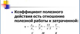
is called the source efficiency factor.
In Fig. 1.11.1 graphically shows the dependences of the source power Pist, the useful power P released in the external circuit, and the efficiency factor η on the current in the circuit I for a source with an emf equal to and internal resistance r. The current in the circuit can vary from I = 0 (at ) to (at R = 0).
| Figure 1.11.1. Dependence of source power Pist, power in the external circuit P and source efficiency η on current strength |
From the above graphs it is clear that the maximum power in the external circuit Pmax, equal to
is achieved at R = r. In this case, the current in the circuit and the efficiency of the source is 50%. The maximum value of the source efficiency is achieved at I → 0, i.e. at R → ∞. In the event of a short circuit, the useful power P = 0 and all the power is released inside the source, which can lead to its overheating and destruction. The efficiency of the source goes to zero.
EMF source
For the existence of direct current in a circuit, it is necessary to continuously separate electric charges, which, under the influence of Coulomb forces, tend to connect. This requires outside forces. EMF characterizes the action of these external forces. And this work itself is carried out inside the EMF sources. Electric charges inside EMF sources move against Coulomb forces under the influence of external forces.
Comparing the electric current with the flow of liquid in the pipes, we can say that the source works like a pump that supplies water from the lower reservoir to the upper one, from which it flows under the influence of gravity into the lower reservoir.
In everyday life, a “current source” is often inaccurately called any source of electrical voltage (battery, generator, socket), but in a strictly physical sense this is not so; moreover, voltage sources usually used in everyday life are much closer in their characteristics to an EMF source than to current source due to the presence of internal resistance.
Currently, many different EMF sources are produced - from small watch batteries to generators.
Inside the current source, charge separation occurs due to processes occurring inside the source, for example, chemical processes.
Galvanic cell
- a chemical current source based on the interaction of two metals and (or) their oxides in an electrolyte (batteries, accumulators).
Generators
- create current by expending mechanical energy.
Thermoelements
- use the energy of thermal motion of charged particles.
Photocells
- create current using light energy.
Now, let's move on to the main thing.
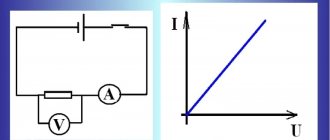
The basis of the science of electricity is Ohm's law.
An experiment carried out by this German physicist led him to the following belief: the current I passing through a metal conductor is proportional to the voltage at its ends, or I = U/R
Here, voltage is the difference, figuratively speaking, of “pressures” created by two points in an electrical circuit. It is measured in volts. Electric current is the number of electrons that a section of an electrical circuit allows through and is measured in amperes. Resistance is the property of a chain to prevent this movement. In honor of the aforementioned physicist, it is measured in ohms. In other words, a conductor through which a current of 1 ampere passes at a voltage of 1 volt has a resistance of 1 ohm.
All other electrical equipment “dances” because of this.
Electrical circuit efficiency
The efficiency factor under consideration is primarily associated with physical quantities characterizing the speed of conversion or transmission of electricity. Among them, power, measured in watts, comes first. There are several formulas to determine it: P = U x I = U2/R = I2 x R.
Electrical circuits may have different voltages and charge amounts, and accordingly, the work performed is also different in each case. Very often there is a need to estimate the speed at which electricity is transmitted or converted. This speed represents the electrical power corresponding to the work done in a certain unit of time. In the form of a formula, this parameter will look like this: P=A/∆t. Therefore, work is displayed as the product of power and time: A=P∙∆t. The unit of work used is the joule (J).
In order to determine how efficient a device, machine, electrical circuit or other similar system is in relation to power and operation, efficiency is used. This value is defined as the ratio of usefully expended energy to the total amount of energy entering the system. Efficiency is denoted by the symbol η, and is defined mathematically as the formula: η = A/Q x 100% = [J]/[J] x 100% = [%], in which A is the work performed by the consumer, Q is the energy given by the source . In accordance with the law of conservation of energy, the efficiency value is always equal to or below unity. This means that useful work cannot exceed the amount of energy expended in doing it.
Load efficiency
Reactive power
Whatever the power of the source, the efficiency of electrical appliances will never be 100%.
Exception. The heat pump principle used in the operation of refrigerators and air conditioners brings their efficiency closer to 100%. There, heating one radiator leads to cooling of the other.
Otherwise, energy is spent on extraneous effects. To reduce this expense, you need to pay attention to the following factors:
- when arranging lighting - on the design of lamps, the design of reflectors and the color of the premises (reflective or light-absorbing);
- when organizing heating - for thermal insulation of heat pipes, installation of heat recovery exhaust devices, insulation of walls, ceilings and floors, installation of high-quality double-glazed windows;
- when organizing electrical wiring, select the correct brand and cross-section of conductors according to the future connected load;
- when installing electric motors, transformers and other AC consumers - by the cosϕ value.
Reducing the cost of losses clearly leads to an increase in efficiency when the energy source performs work on the load.
Reducing the influence of factors causing power loss increases the percentage of useful power required to perform work. This is possible by identifying the causes of losses and eliminating them.
How is horsepower related to watts?
Whether we measure power in “horsepower” or “watts,” we are still talking about the same thing: how much work can be done in a given period of time. These two units are not numerically equal, but they express the same thing. In fact, European car manufacturers typically advertise their engine power in kilowatts (kW) or thousands of watts rather than horsepower! These two units of power are related to each other by a simple formula:
\[1\text{horsepower} = 745.7\W\]
Thus, our 100 HP diesel and motorcycle engines can also be rated as "74570 W" engines, or more precisely as "74.57 kW" engines. In European technical documentation, this parameter would be the norm rather than the exception.
How to calculate the power of a resistor?
The resistor has a rather important parameter, which completely affects the reliability of its operation.
This parameter is called dissipation power. It was already mentioned in the article about resistor parameters. The DC power itself is calculated using a simple formula:
As you can see, power depends on voltage and current. In a real circuit, a certain current flows through a resistor. Since the resistor has resistance, the resistor heats up under the influence of flowing current. It releases some heat. This is the power that is dissipated by the resistor.
If you install a resistor with less dissipation power than required in the circuit, the resistor will heat up and eventually burn out. Therefore, if you need to replace a 0.5 Watt resistor in a circuit, then set it to 0.5 Watt or more. But no less!
Each resistor is designed for its own power. The standard series of power dissipation resistors consists of the following values:
The larger the resistor, the more power it is designed to dissipate, as a rule.
Let's say we have a resistor with a nominal resistance of 100 ohms. A current of 0.1 Ampere flows through it. What power should this resistor be rated for?
Here we need a formula. She looks like this:
R(Ohm) – circuit resistance (in this case, a resistor);
I(A) – current flowing through the resistor.
All calculations should be made strictly observing dimensions. So, if the resistance of the resistor is not 100 Ohms, but 1 kOhm, then you need to substitute the value in Ohms into the formula, i.e. 1000 Ohm (1 kOhm = 1000 Ohm). The same rule applies to other quantities (current, voltage).
Let's calculate the power for our resistor:
We received a power of 1 Watt. Now a small digression.
In a real circuit, it is necessary to install a resistor with a power one and a half to two times higher than calculated.
Therefore, a resistor with a power of 2 W is suitable for us (see the standard series of resistor powers).
There is also another formula for calculating power. It is used when the current flowing through the resistor is unknown.
Everything would be fine, but in life there are cases when series or parallel connection of resistors is used. How to calculate the power dissipation for each of the resistors in a series or parallel circuit?
How to calculate the power of a resistor?
The resistor has a rather important parameter, which completely affects the reliability of its operation. This parameter is called dissipation power. It was already mentioned in the article about resistor parameters.
The DC power itself is calculated using a simple formula:
As you can see, power depends on voltage and current. In a real circuit, a certain current flows through a resistor. Since the resistor has resistance, the resistor heats up under the influence of flowing current. It releases some heat. This is the power that is dissipated by the resistor.