Ammeters are used to measure the strength of direct or alternating electric current. The graphic designation of this device on electrical diagrams is a circle with the letter “A” placed inside. This measuring device determines the strength of electric current in amperes, milliamps or microamps. An ammeter is connected in series to the open circuit.
Application of ammeters:
Ammeters are used in industry, telecommunications, laboratory research and other fields of activity to measure direct or alternating electric current in the range from units of μA to tens of kA. In this case, the value of the measured current should not exceed the maximum scale value of the device, taking into account the connection diagram. Depending on the measurement limit, modern ammeters are divided into:
- microammeters;
- milliammeters;
- ammeters;
- kiloammeters.
Safe work rules
When using the device, the following safety precautions must be observed:
- The device must not be shaken or dropped.
- If the arrow on the device goes off scale, you must immediately open the circuit.
Diagram of correct connection of the device
Connection rules:
- Connect the positive terminal of the device to the positive terminal of the current source. If the circuit consists only of a current source, the device cannot be connected to it!
- The ammeter is connected in series. The connection occurs with the element whose current strength needs to be measured.
- The device must be in a horizontal position.
Knowing the connection rules and types of devices, you can choose the most suitable ammeter for measurement.
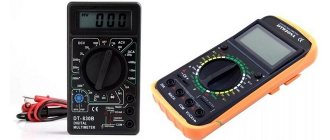
What types of ammeters are there?
Depending on the type, ammeters are divided into measuring devices:
- direct current;
- alternating current.
The following types of ammeters exist:
- magnetoelectric - used to measure small quantities of direct electric current;
- electromagnetic - provide measurement of alternating (frequency 50 Hz) and direct current;
- electrodynamic - measure alternating (frequency up to 200 Hz) and direct current;
- thermoelectric - designed to measure the value of high-frequency alternating electric current;
- ferrodynamic - are self-recording instruments and are used in automatic measurement systems.
Depending on the type of scale used, these devices are:
- switches;
- electronic (digital).
Classification of voltmeters
According to the operating principle of the measuring module:
Equipped with an electromechanical actuator. The measurement process is based on the direct linear dependence of mechanical movement on the measured value. The arrow is placed on a winding frame, which is located on a free axis inside a constant magnetic field.
When voltage is applied to the frame, an electromagnetic field appears around it.
The head rotates in the magnetic field of a permanent magnet.
Equipped with electronic measuring instruments. A special unit converts the applied voltage into a pulse or analog code, which is transmitted to the display unit. It, in turn, can be digital or analog.
By purpose:
- Direct current voltage (EMF) measurement;
- Measurement of voltage (EMF) of alternating current;
- Instruments capable of measuring pulse voltage;
- Phase sensitive. The quadrature component of the first harmonic voltage is measured. The main application is audio equipment;
- Selective. They measure voltage in the form of a sine wave in a narrow frequency range. Tuning the measuring head to the frequency contributes to a more accurate measurement of the value;
- Universal. From the name it follows that they can measure voltage (EMF) in any conditions. As a rule, they are equipped with sets of quenching resistors (shunts).
By execution method:
Portable. Since no power is required to operate the instrument (except for electronic systems), these voltmeters take up little space and have a convenient housing. A type of device is. Despite its compact size, the measurement accuracy is quite high.
Stationary. They are housed in a powerful housing and, as a rule, have a large scale. They have the ability to mechanically install the device both horizontally and the measurement limit. They have a higher cost, but good accuracy allows such devices to be used even in laboratories.
Shield ones. They look portable and are installed in the niches of control cabinets.
Important! Working head technology allows voltmeters to operate continuously, in 365/24 mode. This is very convenient for continuous monitoring of electrical installation parameters.
The device has very low internal resistance. Moreover, regardless of the design: mechanical or electronic. During the measurement, it does not matter how the voltmeter works or where the voltage is measured. The circuit will not be affected in any way.
Operating principle of an ammeter
The operation of different types of ammeters is based on different operating principles. The methods used to measure electric current mainly depend on the application of the device.
The principle of operation of a magnetoelectric ammeter is based on the fact that a constant magnetic field and electric current flowing through the windings of the frame cause the occurrence of torque. The flow of electric current through the device causes the needle to move. The latter is directly connected to the frame. Therefore, the angle of rotation of the arrow is directly proportional to the amplitude of the measured electric current.
The design of an electrodynamic ammeter includes a fixed and moving coil. To measure currents of small magnitude, they are connected in series, and for large currents - in parallel. The needle is attached to the moving coil and moves as a result of the interaction between the currents flowing in the fixed and moving coil.
The design of a thermoelectric ammeter is based on a magnetoelectric device with a contact or non-contact transducer. The latter is a conductor with a thermocouple welded to it. Passing through the converter, the electric current causes it to heat up, which is detected by a thermocouple. The resulting thermal radiation affects the magnetoelectric device. Its frame deviates by an angle proportional to the value of the flowing electric current.
The operation of a digital ammeter is based on analog-to-digital conversion of the amplitude of the measured current. Passing through an analog-to-digital converter (ADC), the signal is quantized by time and then by level. The received information is converted into digital form and displayed on the display.
Device designations
When labeling products, manufacturers indicate certain designations that reflect information about the operating principle of the equipment. A capital letter in the marking indicates the type of operation of the device. The main options are:
- “M” or “K” means that the device is modernized or contact;
- “D” - electrodynamic device;
- “H” means that the design is self-writing;
- "P" indicates measuring type transducers;
- induction devices are designated by the letter “I”;
- "L" stands for ratiometers.
A variety of devices have many classification options
When choosing a specific device, take into account the designations in the labeling. Before using new equipment for the first time, it must be configured according to the instructions.
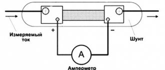
How to calculate a shunt for an ammeter?
In cases where it is necessary to measure electric current exceeding the maximum value of the ammeter scale, it is necessary to use a shunt. Its resistance is calculated using the following formula:
Rsh=(Ra*Ia)/(Ish-Ia)
Wherein:
- Rsh is the required shunt resistance (in Ohms);
- Ra – internal resistance of the ammeter (in Ohms);
- Ia is the maximum current value measured by an ammeter (in Amperes);
- Ish is the approximate value of the measured current (in Amperes).
Applicability
Tractors T-150 K, 158, DT-175S, 75 U, T-130 MG, PAZ-672, GAZ-71, 66-01, UAZ-469RKh, URAL-479
Ammeter Installation
On most cars, to monitor the operation of the power supply system, only a charge indicator lamp is used, which does not monitor the condition of the battery, charging current, voltage in the on-board network and, in addition, does not allow identifying a number of faults in the circuits. Complete information about the operation of the generator and battery can be obtained by equipping the car with an ammeter
and a voltmeter.
Ammeter
Usually it is connected to the break in the wire going from the generator to the battery.
For example, on VAZ cars between the “B+” terminals of the generator and the “+” terminals of the battery. The Ammeter
connected using a wire of suitable cross-section.
For example, the AP-111 ammeter
must be connected with a wire with a cross-section of at least 20 kV, otherwise the wire will heat up.
The Ammeter
itself may also heat up a little during operation, because There is a shunt installed inside it, which also generates heat when the current is high; this is not a malfunction.
The voltmeter can be connected much easier, in any place where there is a “+”. Accordingly, one contact is connected to the body; the other is more conveniently connected to the ignition switch terminal where “+” appears when the ignition is turned on. The figure shows a typical circuit diagram for connecting an Ammeter
and voltmeter
Ammeter connection diagram
and voltmeter:
1 - battery
2 - generator
3 - mounting block
4 - ignition switch
5 - battery charge indicator lamp located in the instrument cluster
6 - ammeter
Everyone should know the rules of how to connect an ammeter. For example, such knowledge is often used when drawing up tasks for experimental rounds of school Olympiads or laboratory work.
Let's start with the principle of operation of an ammeter. The fact that it measures current is obvious simply from the name. This happens as follows: the electric current moving through the circuit also passes through the device. In this case, a torque is created, which causes the dynamic (moving) part to deflect at a certain angle. This deviation is directly proportional to the current strength. This is then displayed visually, for example, by moving an arrow or displaying a number.
Let's remember the concepts of parallel and serial connections. If you need to measure the current strength at some receiver, then its value must coincide with what passes through the ammeter. This is typical specifically for a serial connection.
However, the connection method is not the only important condition for how to connect an ammeter. The resistance of the ammeter is no less important.
If it suddenly turns out to be higher than the resistance of the receiver, when the device is connected, the circuit operation system will be disrupted, and the value of the current acting on the receiver will change.
When connecting in a gap, it does not matter whether you connect the “plus” to the power source or device. The main thing is to do it in series and not in parallel.
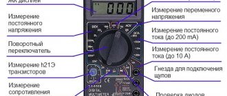
There are several types of ammeters. These include analog and digital. It can be used to measure both direct and alternating current. However, for any of them, the rules for connecting an ammeter remain unchanged. You just have to check what current a particular device measures. This is indicated on the device itself. If the current is direct, “=” is indicated, if alternating – “~”. This must be done, otherwise the ammeter will not work.
In addition, when working with electricity, you must follow safety rules. If you come into contact with exposed wires and are careless, there is a possibility that you will receive, if not an electrical burn, very unpleasant sensations. This is especially true for real installations, because in a school laboratory, as a rule, the circuit is powered by a battery, and the current is not too high.
Thus, a characteristic feature of the ammeter is its series connection. This limits the number of ways to connect an ammeter.
Ammeter internal resistance
For correct operation, the value of the internal resistance of the ammeter must be an order of magnitude less than the value of the circuit resistance. In some cases, such information is not available. Then you should measure the internal resistance of the ammeter used. To do this, a load resistor and an ammeter are connected in series to the power source, and a sensitive voltmeter is connected in parallel to the latter. After switching on the circuit, instrument readings are taken. The value of the internal resistance of an ammeter is determined as the ratio of the readings of a sensitive voltmeter and an ammeter.
Voltage measurement.
A device designed to measure voltage is called a voltmeter , and, unlike an ammeter, it is connected to the circuit parallel to the section of the circuit at which the voltage needs to be determined. And, again, in contrast to an ideal ammeter, which has zero resistance, the resistance of an ideal voltmeter should be equal to infinity. Let's figure out what this is connected with:
If there were no voltmeter in the circuit, the current through the resistors would be the same and determined by Ohm’s Law as follows:
So, the current value would be 1 A, and accordingly the voltage on resistor 2 would be equal to 20 V. This is all clear, but now we want to measure this voltage with a voltmeter and turn it on in parallel with
. If the resistance of the voltmeter were infinitely large, then no current would simply flow through it (), and the device would not have any effect on the original circuit. But since it has a finite value and is not equal to infinity, a current will flow through the voltmeter and, in connection with this, the voltage across the resistor will no longer be the same as it would be in the absence of a measuring device. That is why the ideal voltmeter would be one through which no current would pass.
As with the ammeter, there is a special method that allows you to increase the voltage measurement limits of the voltmeter. To do this, it is necessary to connect an additional resistance in series with the device, the value of which is determined by the formula:
This will cause the voltmeter to be n times less than the measured voltage. As usual, let's look at a small practical example