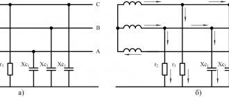
Networks with a voltage of 6-35 kV operate predominantly in the mode with an isolated neutral. In normal mode, load currents flow through the phase wires of such a network, as well as capacitive and leakage currents.
Network with isolated neutral in normal mode
Capacitive currents are caused by the phase capacitance relative to the ground, and leakage currents are caused by the active conductivity of the insulation. Compared to capacitive currents, leakage currents are small and amount to 2-6% of capacitive currents, so they can be neglected in calculations.
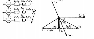
When one phase, for example phase “C”, is short-circuited to ground, the neutral voltage Un becomes equal to the voltage of the damaged phase. The current distribution pattern changes accordingly.
Since, as a result of damage, the capacitance of phase “C” becomes shunted, the voltage Ucn = 0 (if we neglect the voltage drop across the longitudinal resistance of the power line), the capacitive current due to the capacitance C0c becomes equal to zero.
In this case, a capacitive ground fault current will flow through the damaged phase “C”, equal to the capacitive current of the undamaged phases
Iз = -(IсА + IсВ).
The “-” sign indicates that the current is directed in the opposite direction, that is, towards the power source, and not away from it.
Network with isolated neutral during short circuit
To determine the settings for the operation of current protection against ground faults, the need to compensate for capacitive ground fault currents, it is necessary to be able to determine the ground fault current of the line.
1. Main characteristics of OZZ
One of the most common types of faults on power lines is a single-phase ground fault (SGF), a type of fault in which one of the phases of a three-phase system is shorted to ground or to an element electrically connected to ground. SPD is the most common type of damage, accounting for about 70-90% of all damage in electrical power systems. The course of physical processes caused by this damage largely depends on the operating mode of the neutral of a given network.
In networks where a grounded neutral is used, a phase-to-ground fault results in a short circuit. In this case, the short-circuit current flows through a closed circuit formed by grounding the neutral of the primary equipment. Such damage leads to a significant jump in current and, as a rule, is immediately turned off by the action of a relay protection, by disconnecting the damaged area.
Electrical networks of voltage classes 6-35 kV operate in a mode with an isolated neutral or with a neutral grounded through a large additional resistance. In this case, a phase-to-ground short circuit does not lead to the formation of a closed circuit and the occurrence of a short circuit, but the short circuit is closed through the capacitances of the undamaged phases.
The magnitude of this current is insignificant (reaches about 10-30 A) and is determined by the total capacity of the undamaged phases. In Fig. Figure 1 shows diagrams of a 3-phase network in modes before and after the occurrence of an electrical fault.
Figure 1 – Network diagram with an isolated neutral a) in normal mode;
b) with OZZ Such damage does not require immediate shutdown, however, its prolonged impact can lead to the development of an emergency situation. However, during OZZ in networks with an isolated neutral, processes occur that affect the operating mode of the electrical network as a whole.
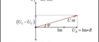
In Fig. Figure 2 shows a vector diagram of voltages.
Figure 2 – Voltage vector diagrams a) in normal mode; b) with acute respiratory disease
In the case of OZZ, a violation of the symmetry of linear phase voltages occurs, the voltage of the damaged phase decreases to almost 0, and the two “healthy” phases rise to the linear level. In this case, the linear voltages remain unchanged.
Author: A. A. Kosyakov
Introduction
Known methods for calculating short-circuit currents in high-voltage electrical installations now generally seem to be well-established and time-tested, since one of the purposes of calculating short-circuit currents is a very important task for the normal functioning of an electrical power facility - the selection and configuration of relay protections, which requires calculations of maximum and minimum three-phase short circuit currents in electrical installations with an insulated neutral of 6-35 kV [1, 2].
When performing an assessment of the technical condition (inspection) of grounding devices of electrical installations, carrying out projects for the reconstruction of grounding devices of electrical installations, another task arises related to the calculation of short circuit current - calculation of the thermal resistance of grounding conductors and grounding conductors. In this case, the design mode in electrical installations with an insulated neutral of 6-35 kV is the mode of a two-phase short circuit to ground [3, 4, 5, 6].
As a rule, the calculation of the two-phase short circuit to earth current IK2 is carried out according to the well-known formula [2]
(1)
where IK3 is the calculated value of the maximum three-phase short circuit current.
Formula (1) does not take into account the path of the two-phase short circuit current, which also passes through the grounding device of the electrical installation. Since three-phase short circuit currents IK3 are not closed through the grounding device of the electrical installation, the design scheme for determining them does not include the inclusion of the resistance of the grounding device in the short circuit circuit. Accordingly, the value of the two-phase short circuit to earth IK2, determined by formula (1), will differ from the current value calculated taking into account the equipment grounding characteristics - not only the resistance of the grounding device, but also the resistance of the metal bond of the equipment to the grounding device.
In most practical cases of inspection and design of grounding devices, the use of the value of the two-phase short circuit to earth current, calculated according to formula (1), does not raise questions among customers of the inspection and design products. However, in May 2016, in the process of approving the reporting documentation for the inspection of the grounding device and the electromagnetic environment of the Novosibirsk CHPP-2 - a branch of Siberian Energy Company JSC, carried out by Alpha EMS LLC, the specialists of Alpha EMS LLC were faced with the request of the customer for the survey to apply to calculate the thermal resistance of grounding conductors and equipment grounding electrodes 10 kV two-phase short circuit current, calculated taking into account the equipment grounding characteristics - the resistance of the grounding device and the resistance of the metal bond of the equipment to the grounding device. The basis for this requirement was the customer’s desire to eliminate excess costs for the reconstruction of the grounding device associated with incorrect calculation of the two-phase short circuit to earth current according to formula (1).
An analysis of existing regulatory documentation on the calculation of short circuit currents, as well as other scientific and technical information on this issue, showed that there is currently no experience in calculating two-phase short circuit currents taking into account the equipment grounding characteristics.
The purpose of this work is to derive calculation formulas for determining the two-phase short circuit current, taking into account the characteristics of equipment grounding - the resistance of the grounding device and the resistance of the metal bond of the equipment to the grounding device.
1. Method for calculating the two-phase short circuit current used in operation
When performing a survey of the grounding device and the electromagnetic environment of the Novosibirsk CHPP-2, carried out by Alpha EMS LLC in February 2016, as the initial data for calculating the thermal resistance of grounding conductors and grounding conductors of 10 kV equipment by the relay protection and automation service of Siberian Energy Company JSC a three-phase current of 79090 A and an operating time of the main protection of 0.1 s were provided.
In accordance with the results of the calculation using formula (1), the two-phase fault current on 10 kV equipment was taken equal to 68494 A. This value of the short circuit current, in accordance with clause 2.1.1 RD 153-34.0-20.525-00 [3], according to the thermal resistance condition, the minimum permissible cross-section of grounding conductors and grounding conductors corresponds to mm2,
where t is the duration of the main protection, s. Since the minimum cross-section of the grounding conductors and grounding conductors of the 10 kV equipment of Novosibirsk CHPP-2 at the time of the inspection was 288 mm2, it was concluded that they did not comply with the thermal resistance condition and recommendations were given to carry out repairs in the scope of installing additional grounding conductors and grounding conductors of the 10 kV equipment.
These recommendations for repairing the grounding device did not meet the customer’s desire to minimize repair costs. To eliminate these costs, the relay protection and automation service of Siberian Energy Company JSC calculated the current of a two-phase short circuit to ground, taking into account the resistance of the grounding device and the resistance of the metal bond of the equipment to the grounding device, and provided a new value of the two-phase fault current on equipment of 10 kV - 34682 A. The calculation was performed in the AWP SRZA program [7], with the provision of a calculation file and a method for specifying a calculated accident - a two-phase short circuit to ground (Fig. 1).
Rice. 1. Window of the AWP SRZA program - setting a two-phase short circuit to ground at the design point
2. Standard approach to calculating the current of a two-phase short circuit to ground
The AWP SRZA program is the main software tool for calculating short-circuit currents, used in the energy sector of the Russian Federation, as well as in the energy sector of Kazakhstan, Mongolia, Belarus, Latvia and Lithuania. At the same time, the method for calculating the current of a two-phase short circuit to earth in electrical networks with an isolated neutral in this program is essentially no different from the method of calculating the current of a two-phase short circuit between phases at one point using formula (1). At the same time, clause 15.3 of STO 56947007-29.130.15.114-2012 [5] states that when calculating the current of a two-phase short circuit to earth, the points of short circuit of different phases should be located at the points most distant from each other within the territory occupied by a network with an isolated neutral, and in clause 8.6 of STO 56947007-29.130.15.105-2011 [4] it is clarified that one of the points of a two-phase short circuit must be taken outside the grounding device for which the calculation is being made.
The design electrical circuit corresponding to the calculation method of the automated manual protection system program (Fig. 1) is presented in Fig. 2. The design electrical diagram that meets the requirements of regulatory documents for the inspection and design of grounding devices in electrical installations is shown in Fig. 3.
Rice. 2. Electrical circuit for calculating the current of a two-phase short circuit of phases B and C to ground, implemented in the AWP SRZA program
Rice. 3. Electrical diagram for calculating the current of a two-phase short circuit to earth of phases B and C, provided for by the regulatory documentation for the inspection and design of grounding devices of electrical installations
On the diagrams in Fig. 2, 3 are marked:
IK – two-phase short circuit to ground current flowing through the grounding conductor;
EA, EB, EC – maximum phase voltages of the equivalent generator;
UBC – maximum linear phase voltage of the BC equivalent generator;
ZС – equivalent network impedance to short circuit current;
ZP – phase impedance of the most remote consumer of the electrical network with an isolated neutral;
RMC – active resistance of metal connection between equipment and grounding device;
RZU – active resistance of the grounding device.
The characteristics of equipment grounding (resistance of the grounding device and resistance of the metal bond of the equipment to the grounding device) are accepted as active, since in accordance with RD 153-34.0-20.525-00 [3] and STO 56947007-29.130.15.105-2011 [4] when inspecting grounding devices, as a rule, only the active component of the specified resistances is measured. If the reactive components of the resistance of the grounding device and the metal connection of the equipment with the grounding device have been measured, they can be introduced into the circuit in series with the corresponding active resistances.
The resistances RMC and RZU are entered into the AWP SRZA program (Fig. 2) for each closed phase, which is due to the fact that the AWP SRZA program calculates asymmetrical short circuits using the method of symmetrical components. This feature of the AWP SRZA program is due to its field of application - the calculation of short-circuit currents for the selection and configuration of relay protection devices, performed in accordance with RD 153-34.0-20.527-98 [8] using the method of symmetrical components.
In accordance with clause 5.9.2 of RD 153-34.0-20.527-98 [8], the current of a two-phase short circuit to ground is determined by the expression
(2)
where EF is the maximum phase voltage of the equivalent generator;
Z1 – total equivalent resistance of the positive sequence equivalent circuit relative to the point of asymmetrical short circuit;
Z2 is the total equivalent resistance of the negative sequence equivalent circuit relative to the point of asymmetrical short circuit. In accordance with clause 3.8.1 RD 153-34.0-20.527-98 [8] Z2 = Z1;
Z0 is the total equivalent resistance of the zero-sequence equivalent circuit relative to the point of asymmetrical short circuit.
The value of Z0 is determined by different formulas in clause 4.2.5 RD 153-34.0-20.527-98 [8] for overhead and cable power lines of various types. Moreover, all formulas in clause 4.2.5 RD 153-34.0-20.527-98 [8] do not include equipment grounding characteristics.
The method for calculating the current of a two-phase short circuit to ground according to GOST R 52735-2007 [9] is completely similar to the calculation according to RD 153-34.0-20.527-98 [8].
Scheme according to Fig. 3, made in accordance with STO 56947007-29.130.15.105-2011 [4] and STO 56947007-29.130.15.114-2012 [5] for calculating the current of a two-phase short circuit to the ground for the purpose of calculating the thermal resistance of grounding conductors and grounding conductors has the following features:
1) the diagram includes the metal bond resistance of equipment with a grounding device only at the facility for which the thermal resistance of grounding conductors and grounding conductors is assessed, but does not include the metal bond resistance of equipment with a grounding device at a remote network site with an isolated neutral. This is due to the fact that, in accordance with clause 8.2 of STO 56947007-29.130.15.105-2011 [4], at the inspection object, the resistance of the metal connection between the equipment and the grounding device is measured relative to a reference point (the grounding conductor of other equipment) that has a satisfactory metal connection with the ground electrode. Thus, the measured metal bond resistance includes at least two transition (contact) resistances between the equipment and the grounding device;
2) the diagram does not include the resistance of the grounding device of a remote network object with an isolated neutral, since when performing an inspection of the grounding device of a specific object (power plant or substation), measuring the resistance of the grounding devices of all remote network objects with an isolated neutral seems practically impossible due to the large volume and the cost of this work. If the resistance of the grounding device of a remote network object with an isolated neutral is known, RZU in the diagram according to Fig. 3 can be defined as the sum of the resistances of the grounding devices of the examined object and a remote network object with an isolated neutral.
3. Directions for the development of methods for calculating the current of a two-phase short circuit to ground
One of the objectives of this work was to identify modern approaches to calculating two-phase short circuit currents to ground for the purpose of calculating the thermal resistance of grounding conductors and ground electrodes. This work was carried out by searching for scientific papers on the specified topic in open sources. The scientific works closest to the topic of this article are given in the sources [10, 11, 12, 13, 14].
The results of the analysis of the directions of development of methods for calculating the current of a two-phase short circuit showed:
1) not a single scientific work has found models for calculating ground short circuit current that take into account the characteristics of equipment grounding - the resistance of the grounding device and the resistance of the metal connection between the equipment and the grounding device;
2) the main calculation method for calculating short-circuit currents is the method of symmetrical components. Other methods for calculating electrical circuits (methods of Kirchhoff’s laws, loop currents, nodal potentials, superposition, equivalent generator), despite the normatively established admissibility of their use for calculating short-circuit currents (clause 4.4 of GOST R 52735-2007 [9], clause 3.7 .1 RD 153-34.0-20.527-98 [8]), are used for calculations extremely rarely;
3) improvement of the method of symmetrical components for calculating two-phase short circuits is carried out in the direction of:
— taking into account the load resistance of the consumer in the open, third phase;
— taking into account arc processes during a short circuit;
— calculation of short circuit currents when two phases of different voltage classes are closed at one facility (for example, one phase 35 kV and one phase 6 kV);
— calculation of short circuit currents when one phase is closed before a 6-10 kV current-limiting reactor, and the other phase is behind the current-limiting reactor;
— calculation of the superposition of transient processes during multiple short circuits, the transition of one type of short circuit to another.
4. Proposed methods for calculating the current of a two-phase short circuit to ground
4.1. Calculation of the current of a two-phase short circuit to ground, taking into account the load resistance of the consumer
Scheme according to Fig. 3, made in accordance with STO 56947007-29.130.15.105-2011 [4] and STO 56947007-29.130.15.114-2012 [5] for calculating the current of a two-phase short circuit to ground for the purpose of calculating the thermal resistance of grounding conductors and grounding conductors, includes load resistance consumer ZP of the electrical network with an isolated neutral. To calculate this circuit, we perform its equivalent transformation into the circuit according to Fig. 4.
Rice. 4. Converted electrical circuit for calculating the current of a two-phase short circuit to ground of phases B and C, taking into account the consumer load resistance
Calculation of the circuit according to Fig. 4 can be conveniently performed using the nodal potential method. To do this, we perform an equivalent transformation of the circuit according to Fig. 4 into the diagram according to Fig. 5.
Rice. 5. Converted electrical circuit for calculating the two-phase short circuit current using the nodal potential method
In the diagram according to Fig. 5 equivalent resistances
(3)
Then the calculated current of phase B IB using the nodal potential method will be determined by the formula
(4)
The current of a two-phase short circuit to earth flowing through the grounding conductor IK, in accordance with the diagram in Fig. 4 can be determined by Kirchhoff’s second law:
(5)
4.2. Calculation of short circuit current to ground without taking into account the load resistance of the consumer
In the absence of the need to accurately calculate two-phase short circuit to earth currents using formulas (3-5), it seems possible to take the consumer resistance ZP equal to infinity, which corresponds to the operation of a 6-35 kV feeder at no load. When examining and designing a grounding device, the possibility of such an assumption can be determined by the ratio of the maximum operating current and the three-phase short circuit current on 6-35 kV buses - the greater the short circuit current compared to the maximum operating current, the smaller the error will be introduced into the calculation by this assumption.
The converted circuit according to Fig. 4, which does not take into account the load resistance of the consumer, is shown in Fig. 6.
Rice. 6. Electrical circuit for calculating the current of a two-phase short circuit to ground of phases B and C without taking into account the load resistance of the consumer
Calculation of the current of a two-phase short circuit to ground in accordance with the diagram in Fig. 6 can be fulfilled by the formula
(6)
where UЛ is the maximum linear voltage of the equivalent generator.
Often, when examining and designing a grounding device, the equivalent impedance of the network to the short circuit current ZC is not provided as initial data. As a rule, in this case, only the three-phase short circuit current IK3 is provided on the 6-35 kV switchgear buses and the maximum line voltage on the UL buses. The ratio of the active and reactance of the network to the short circuit current is also usually not provided. As a rule, the reactive component of the network impedance to short-circuit current in high-voltage electrical installations is much greater than the active component. Accordingly, the resistance ZC found according to Ohm’s law in this case can be assumed to be reactive:
(7)
where UФ is the maximum phase voltage of the equivalent generator.
It should also be noted that formula (7) can be used, among other things, to find the phase impedance of the most remote consumer of an electrical network with an isolated neutral ZP, since the specified parameter of the electrical network is usually not provided as initial data when examining and designing a grounding device .
Taking into account the above, a simplified formula convenient for practical use for calculating the current of a two-phase short circuit to ground flowing in the grounding conductor will have the following form:
(8)
4.3. Comparison of formulas for calculating the two-phase short circuit current flowing in grounding conductors
A comparison of the results of calculating the current of a two-phase short circuit to earth using the proposed formulas is given in Table. 1 using the example of the first section of 10 kV busbars at Novosibirsk CHPP-2. The following parameters of the 10 kV network, provided by the relay protection and automation service of Siberian Energy Company JSC, as well as equipment grounding characteristics measured by Alpha EMS LLC at the power plant, were taken as initial data for calculations:
1) three-phase short circuit current – 79090 A;
2) maximum linear voltage – 10600 V. Phase angle of the three-phase system – 120º;
3) equivalent impedance of a 10 kV network to short circuit current – 0.002 + j0.077 Ohm;
4) the maximum operating currents of feeders of remote consumers of 10 kV are taken equal to 3000 A, 1000 A, 300 A. The nature of the load is active;
5) resistance of the grounding device – 0.09 Ohm;
6) metal connection resistance of 10 kV equipment with a grounding device – 0.04 Ohm.
Table 1
Calculation results of two-phase short circuit to earth currents
| № | Description of the calculation | Estimated value of short circuit current, A |
| 1 | Calculation using the well-known formula (1), which does not take into account the equipment grounding characteristics | 68494 |
| 2 | Calculation in the AWP SRZA program according to RD 153-34.0-20.527-98 [8] taking into account the characteristics of equipment grounding introduced into the short circuit circuit in series with equivalent phase resistances | 34682 |
| 3 | Calculation using formulas (3-5) in accordance with STO 56947007-29.130.15.105-2011 [4] and STO 56947007-29.130.15.114-2012 [5], taking into account the resistance of a remote consumer with a maximum operating current of 3000 A | 67846 |
| 4 | Calculation using formulas (3-5) in accordance with STO 56947007-29.130.15.105-2011 [4] and STO 56947007-29.130.15.114-2012 [5], taking into account the resistance of a remote consumer with a maximum operating current of 1000 A | 68863 |
| 5 | Calculation using formulas (3-5) in accordance with STO 56947007-29.130.15.105-2011 [4] and STO 56947007-29.130.15.114-2012 [5], taking into account the resistance of a remote consumer with a maximum operating current of 300 A | 69230 |
| 6 | Calculation using formula (6) in accordance with STO 56947007-29.130.15.105-2011 [4] and STO 56947007-29.130.15.114-2012 [5], without taking into account the resistance of a remote consumer and taking into account the ratio of active and reactance of the network to short circuit current | 69364 |
| 7 | Calculation using formula (8) in accordance with STO 56947007-29.130.15.105-2011 [4] and STO 56947007-29.130.15.114-2012 [5], without taking into account the resistance of the remote consumer and the ratio of the active and reactance of the network to short circuit current | 70066 |
conclusions
The results of this work are the following conclusions:
1) in the ARM SRZA program, due to the peculiarities of the symmetrical components method implemented in it, it is fundamentally impossible to calculate the current of a two-phase short circuit to ground flowing through the grounding conductor of 6-35 kV equipment with damaged insulation. The AWP SRZA program, designed for calculating short-circuit currents for the purpose of selecting and configuring relay protections in accordance with RD 153-34.0-20.527-98, calculates short-circuit currents flowing through phase wires, and not through grounding conductors and grounding conductors. Introducing equipment grounding characteristics (resistance of the grounding device and metal bond resistance) into the short circuit circuit in series with equivalent phase resistances leads to a significant underestimation of the calculated current of a two-phase short circuit to ground. This feature of the AWP SRZA program is not its drawback - the AWP SRZA program is simply not intended to perform calculations of two-phase short circuit currents to the ground for the purpose of assessing the thermal resistance of grounding conductors and ground electrodes according to STO 56947007-29.130.15.105-2011 and STO 56947007-29.130.15.1 14 -2012;
2) two-phase short circuit to ground current, calculated according to STO 56947007-29.130.15.105-2011 and STO 56947007-29.130.15.114-2012, taking into account the equipment grounding characteristics (grounding device resistance and metal bond resistance) in a typical case, considered using the example of the Novosibirsk TE C -2, differs slightly from the calculation using the traditionally used formula (1). The error introduced by the ambiguity in the assessment of the seasonal change in the resistance of the grounding device and the corrosion state of the grounding conductors and ground electrodes is at least an order of magnitude greater than the error introduced into the calculation of the two-phase short circuit current to the ground without taking into account the grounding characteristics of the equipment;
3) from a variety of remote consumers of the electrical network with an isolated neutral, to calculate the current of a two-phase short circuit to ground according to STO 56947007-29.130.15.105-2011 and STO 56947007-29.130.15.114-2012, according to formulas (3-5), a minimum power consumer should be selected ( with minimum feeder current). In this case, the calculated value of the short circuit current will be maximum, which will ensure the correct selection of the cross-section of grounding conductors and grounding conductors with a margin;
4) the results of calculations of two-phase short circuit currents using simplified formulas (6) and (8), which do not take into account the characteristics of a remote consumer in a typical case, considered using the example of Novosibirsk CHPP-2, differ from calculations taking into account the characteristics of a remote consumer using formulas (3-5 ) is insignificant. Moreover, calculations using formulas (6) and (8) are much simpler than calculations using formulas (3-5). Accordingly, when examining a grounding device in accordance with STO 56947007-29.130.15.105-2011, it is possible to calculate two-phase short circuit currents for each 6-35 kV device using formula (6) or (8), taking into account the individual resistance of the metal connection between the device and the grounding device , which will increase the reliability of the survey results;
5) calculations of single-phase short circuit currents in electrical installations with a grounded neutral (110 kV and above), performed in the AWP SRZA program, also do not take into account the equipment grounding characteristics due to the peculiarities of modeling the electrical network in the AWP SRZA program in accordance with RD 153-34.0- 20.527-98. To take into account the characteristics of equipment grounding in this case, it seems necessary and sufficient to enter an additional resistance in the AWP SRZA program (the sum of the resistances of the grounding device and the metal connection of the equipment to the ground electrode) at the point of a single-phase short circuit.
Literature
1. Pochaevets V.S. Electrical substations. M.: Zheldorizdat, 2001. – 512 p.
2. Prokhorsky A.A. Traction and transformer substations. M.: Transport, 1983. – 496 p.
3. RD 153-34.0-20.525-00. Guidelines for monitoring the condition of grounding devices in electrical installations.
4. STO 56947007-29.130.15.105-2011. Guidelines for monitoring the condition of grounding devices in electrical installations.
5. STO 56947007-29.130.15.114-2012. Guidelines for the design of grounding devices for substations with voltages of 6-750 kV.
6. Order of the Ministry of Energy of the Russian Federation dated July 8, 2002 No. 204 “Rules for the construction of electrical installations.”
7. Chernyakov V.N., Sedelnikov G.F., Dubranovskaya N.L., Stenina V.V., Rubina E.N. Software package for calculating electrical quantities in case of network damage and relay protection settings // Certificate of the Russian Federation on state registration of a computer program No. 2011618568. Registered in the register of computer programs on October 31, 2011.
8. RD 153-34.0-20.527-98. Guidelines for calculating short-circuit currents and selecting electrical equipment.
9. GOST R 52735-2007. Short circuits in electrical installations. Calculation methods in AC electrical installations with voltages over 1 kV.
10. Veselovsky A.N., Klimov N.A., Klimov S.A. The influence of transition resistance at the fault point on emergency modes of a 35 kV feeder with a three-winding transformer // Proceedings of the Kostroma State Agricultural Academy. Kostroma: KSSA, 2015. pp. 175-179.
11. Migunov S.D. Application of the method of symmetrical components to identify emergency modes in three-phase electric power systems // Electric power industry through the eyes of youth: proceedings of the VI international scientific and technical conference. Ivanovo: ISEU im. IN AND. Lenina, 2015. pp. 125-128.
12. Kanevsky Ya.M. Calculations of currents during a double ground fault before and after a 6-10 kV current-limiting reactor at power plants // Electricity. Moscow: All-Russian Research Institute of Cable Industry, 2005. No. 11. P. 34-41. ISSN 0013-5380.
13. Lyamets Yu.Ya., Nudelman G.S., Zinoviev D.V., Kerzhaev D.V., Romanov Yu.V. Multidimensional relay protection. Equivalence of models // Electricity. Moscow: All-Russian Research Institute of Cable Industry, 2010. No. 1. P. 9-15. ISSN 0013-5380.
14. Vainshtein R.A., Lozinsky K.S., Kolomiets N.V. Calculation of asymmetric modes in the electric power system based on a combination of coordinate systems // News of the Tomsk Polytechnic University. Tomsk: TPU, 2010. No. 4. P. 146-152. ISSN 1684-8519.
Article Kosyakov A.A. Taking into account the resistance of the charger when calculating a two-phase short circuit
Journal Vestnik UrGUPS No. 1 (37) 2018
Consequences of OZZ
Despite the advantages of an isolated neutral, this operating mode has a number of disadvantages:
- Depending on the branching of the network, the capacitive current can range from 0.1 to 500 amperes. This amount of current can pose a danger to animals and people located near the fault; for this reason, these faults must be identified and turned off, just as is done in networks with a solidly grounded neutral.
- In most cases, an arc fault to ground occurs during a short-circuit fault, which can be intermittent. In this case, during an arc fault, overvoltages occur that exceed the rated phase voltage by 2-4 times. The insulation during the circuit may not withstand such overvoltages, as a result of which insulation breakdown may occur at any other point in the network and then the circuit develops into a double short circuit to ground.
- During the development and elimination of short-circuit faults, a ferroresonance effect occurs in voltage transformers, which with a high probability leads to their premature failure.
Despite the listed disadvantages, the OZ does not require immediate damage elimination. According to the PUE, in the event of an emergency, it is possible to operate the network without shutting down the accident for 4 hours, which are allocated to search for the damaged area.
Calculation of the total current of the residual current
When a phase of one of several power lines connected to a common source is faulted to ground, the total current at the point of fault due to the capacitive currents of all power lines can be calculated by several methods.
The first method is to use the specific capacitances of power lines. This calculation method will give the most accurate result and is preferred. The specific capacitances of power lines can be taken from reference literature, or from the technical characteristics of the cable provided by the manufacturer.
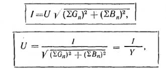
Expression for determining the residual current:
,
where C∑ is the total phase capacity of all power lines, and C∑ = Court l; Court – specific capacity of the network phase relative to ground, F/km; l is the total length of the conductor of one phase of the network.
The second method is applicable for networks with cable power lines. The ground fault current for such a network can be determined by the empirical formula:
,
where UNOM is the rated line voltage of the network, kV; li – cable line length, km; qi – cable core cross-section, mm2.
In addition to these methods, to calculate the total SGC current, you can use the values of capacitive currents of each cable taken from reference literature.
Synchronous and asynchronous electric motors
The own capacitive current of synchronous and asynchronous motors is determined by formula 6.3 [L3, p. 215] and expressed in amperes:
Where:
- fnom. – nominal network frequency, Hz;
- Сд – stator phase capacitance, F;
- Unom. – rated voltage of the electric motor, V.
The stator phase capacity CD is taken according to the manufacturer's data. If these values are missing, you can use the following approximate formulas [L3, p. 215]:
- for non-salient-pole LEDs and IMs with a squirrel-cage rotor:
Where:
- Snom. – rated total power of the electric motor, MVA;
- Unom. – rated voltage of the electric motor, kV.
- for other electric motors:
Where:
- Unom. – rated voltage of the electric motor, V;
- nnom. – rated rotor speed, rpm.
4. Compensatory protection measures
Due to the capacitance distributed along overhead and cable power lines, during a short circuit fault a capacitive current flows at the fault site. In the most severe cases, an electric arc may occur, the combustion of which can lead to the transition of the OZZ into a two- or three-phase circuit and the disconnection of the line by relay protection. As a result, the electricity consumer may temporarily lose power supply.
In accordance with the provisions of the PUE, under normal network operating conditions, special measures must be taken to protect against possible ground faults. To prevent arcing and reduce capacitive currents, capacitive current compensation is used. The values of capacitive currents, above which compensation is required in accordance with the PUE and PTE, are given in Table. 1.
Table 1 – Current values requiring compensation
| Network voltage, kV | 6 | 10 | 20 | 35 |
| Capacitive current, A | 30 | 20 | 15 | 10 |
At lower current levels, it is considered that the arc does not light up or goes out on its own; the use of compensation in this case is not necessary.
Calculation of short circuit current in a 0.4 kV network
To bookmarks
Introduction
In accordance with clause 3.1.8. PUE electrical networks must have protection against short-circuit currents, ensuring the shortest possible shutdown time; it is indicated that the protection must be checked in relation to the smallest rated short-circuit current (hereinafter referred to as the short-circuit current) to the rated current of the fuse link or circuit breaker release. (For more information about choosing protection against short-circuit currents, read the article: Calculation of the electrical network and selection of protection devices)
In 0.4 kV networks with a solidly grounded neutral, the smallest short-circuit current is the single-phase short circuit current, the calculation method of which is given in this article.
Basic concepts and calculation principle
The formula for calculating the short-circuit current itself is simple, it comes from Ohm’s law for a complete circuit and has the following form:
Iкз=Uф/Zф-о
Where:
- Uph - phase voltage of the network (230 Volts);
- Zph-o is the total resistance of the loop (circuit) phase-zero in Ohms.
What is a phase-zero loop (phase-zero)? This is an electrical circuit consisting of phase and neutral conductors, as well as the transformer windings to which they are connected.
In turn, the resistance of this electrical circuit is called the phase-zero loop resistance.
As you know, there are three types of resistance: active (R) , reactive (X) and total (Z) . To calculate the short circuit current, it is necessary to use the total resistance, which can be determined from the resistance triangle:
Note: The sum of the impedances of the neutral and phase conductors is called the impedance of the supply line.
It is quite difficult to calculate the exact resistance of the phase-zero loop, because its resistance is influenced by many different factors, starting with the transition resistance of contact connections and the resistance of the internal elements of protection devices, ending with the ambient temperature. Therefore, for practical calculations, simplified methods for calculating short-circuit currents are used, one of which is given below.
For reference: Short circuit current is determined by calculation, as a rule, only for new and reconstructed electrical installations at the stage of designing the electrical network and selecting its protection devices. In existing electrical installations, it is most advisable to determine the short-circuit current by carrying out appropriate measurements (by direct measurement of the short-circuit current, or by indirect measurement, i.e., measuring the resistance of the phase-to-zero loop and subsequent calculation of the short-circuit current).
Methodology for calculating short-circuit current
1) Determine the total resistance of the supply line up to the short circuit point:
Zl = √(R2l+X2l), Ohm
Where:
- Rl — Line resistance, Ohm;
- Xl — Line reactance, Ohm;
Note: The calculation is made for each section of the line with a different cross-section and/or conductor material, followed by the summation of the resistances of all sections (Zpl=Zl1+Zl2+…+Zln).
The active resistance of the line is determined by the formula:
Rl =Lfo*p/S, Ohm
Where:
- Lfo - Sum of the lengths of the phase and neutral conductors of the line, m;
- p - Specific resistance of the conductor (for aluminum - 0.028, for copper - 0.0175), Ohm* mm2/m;
- S - Conductor cross-section, mm2.
Note: the formula is given taking into account that the cross-sections and material of the phase and neutral conductors of the line are the same, otherwise the calculation must be performed using this formula for each of the conductors individually, followed by summing their resistances.
Line reactance is determined by the formula:
Chl =Lfo*0.6/1000, Ohm
2) Determine the resistance of the supply transformer
The resistance of a transformer depends on many factors such as the power, the design of the transformer and mainly the wiring diagram of its windings. For a simplified calculation, the transformer resistance for a single-phase short circuit (Ztr(1)) can be taken from the following table:
3) Calculate the short circuit current
The single-phase short circuit current is determined by the following formula:
Iкз=Uф/(Ztr(1)+Zpl), Ampere
Where:
- Uph - Phase voltage of the network in Volts (for 0.4 kV networks is taken equal to 230 Volts);
- Ztr(1 ) - Resistance of the supply transformer during a single-phase short circuit in Ohms (from the table above);
- Zpl - Total resistance of the supply line (phase-zero circuit) from the supply transformer to the short circuit point in Ohms.
Example of short-circuit current calculation
For example, take the following simplified single-line diagram:
- Determine the total resistance of the supply line to the point of short circuit
As can be seen from the diagram, there are three sections of the network in total; the resistance must be calculated for each separately, and then the calculated resistances of all sections must be added up.
- Section 1
Rl1 =Lfo*p/S=150*0.028/35=0.12 Ohm
Chl1 =Lfo*0.6/1000=150*0.6/1000=0.09 Ohm
Zl1 = √(R2l+X2l)=√(0.122+0.092)=0.15 Ohm
- Section 2
Rl2 =Lfo*p/S=20*0.028/16=0.035 Ohm
Chl2 =Lfo*0.6/1000=20*0.6/1000=0.012 Ohm
Zl2 = √(R2l+X2l)=√(0.0352+0.0122)=0.037 Ohm
- Section 3
Rl3 =Lfo*p/S=40*0.0175/2.5=0.28 Ohm
Chl3 =Lfo*0.6/1000=40*0.6/1000=0.024 Ohm
Zl3 = √(R2l+X2l)=√(0.282+0.0242)=0.281 Ohm
Thus, the total resistance of the supply line (phase-zero circuit) from the supply transformer to the short-circuit point will be:
Zpl=Zl1 +Zl2 +Zl3 =0.15+0.037+0.281=0.468 Ohm
- Determining the resistance of the transformer
As can be seen from the diagram, the power source is a 160 kVA transformer, with a “star-star” winding connection diagram with the neutral removed. We determine the resistance of the transformer according to the table above:
Ztr(1)=0.16 Ohm
- We calculate the short circuit current
Iкз=Uф/(Ztr(1)+Zpl)=230/(0.16+0.468)=366 Ampere
Was this article useful to you? Or maybe you still have questions ? Write in the comments!
Didn’t find an article on the website on a topic that interests you regarding electrical engineering? Write to us here. We will definitely answer you.
↑ Up
5
https://elektroshkola.ru/elektrotexnicheskie-raschety/raschet-toka-korotkogo-zamykaniya-v-seti-04-kv/
Arc suppression reactor
To limit capacitive currents, a special arc suppression reactor is introduced into the transformer neutral (Fig. 3).
Figure 3 – Arc suppression reactor
This method is the most effective means of protecting electrical equipment from ground faults and compensating for capacitive current. With its help, it is possible to reduce (compensate) the current of a single-phase ground fault that occurs immediately after an accident.
6. Main characteristics of the DGR
An arc suppression reactor (AHR) is an electrical device designed to compensate for capacitive currents in electrical networks with an isolated neutral that occur during single-phase ground faults (OSF). The main regulatory document regulating the operation, installation and superstructure of the DGR is R 34.20.179.
Arc suppression reactors must be connected to the neutrals of transformers, generators or synchronous compensators through disconnectors. A current transformer must be installed in the reactor grounding circuit. Recommended DGR connection diagrams are shown in Fig. 4.
Figure 4 – DGR connection diagram: a) connecting the DGR to MV transformers; b) connecting the DGR to the neutral of the power transformer
The inductance of the DGR is selected from the condition of equality of the capacitive conductivity of the network and the inductive conductivity of the reactor. Thus, capacitive current is compensated. The capacitive current is summed up at the fault point by an inductive current equal to it and opposite in phase, as a result only the active part remains, usually very small, these are leakages through the insulation of cable lines and active losses in the DGR (usually do not exceed 5 A), which is not enough to cause electric arc and step voltage. Current-carrying circuits remain undamaged, consumers continue to be supplied with electricity.
Modern DGRs have various design features and are manufactured for a huge range of capacities. Table 2 shows a number of parameters of arc suppression reactors from different manufacturers.
Table 2 – DGR parameters
| Reactor type | RDMR | RZDPOM | RUOM | ASR, ZTC | TRENCH |
| Cooling | Oily | Oily | Oily | Oily | Oil, dry |
| Execution | Single | Single | Single | Single, combo | Single, combo |
| Voltage class, kV | 6, 10 | 6, 10, 20, 35 | 6, 10 | 6, 10, 20, 35 | 6, 10, 20, 35 |
| Frequency of regulation | 8–25 | 5 | 10 | 10 | 10 |
| Power range, kVA | 300–820 (1520) | 120–1520 | 90–1520 | 50–8000 | 100–1000 |
When selecting an arc suppression reactor, the following order is recommended; the maximum capacitive earth fault current is determined; the total power of the reactors is determined from the condition of full compensation of the capacitive current (resonant tuning); the number of reactors is determined (if IC > 50 A, it is recommended to use at least two reactors);
Calculation of capacitive ground fault current of an overhead line
The capacitive current of the overhead line can be approximately determined by the formula [3]:
Is.vl = (2.7 ÷ 3.3) U l 10-3, A,
where: U – network voltage, kV (6, 10 or 35 kV); l – line length, km.
For 6-10 kV lines, as well as 35 kV lines without cables, a coefficient of 2.7 is accepted; for 35 kV lines on wooden supports with cables – 3.3; on metal supports with cables – 3.0.
The capacitive current of a double-circuit line can be determined by the formula:
Is.2c.vl = (1.6 ÷ 1.3) Is.vl, A,
where: Is.vl – capacitive current of a single-circuit overhead line, A
The increase in the capacitive current of the network due to the capacity of substation equipment can be approximately estimated for overhead and cable networks of 6-10 kV - by 10%, for overhead networks of 35 kV - by 12%.
For 35 kV cable networks, the increase in capacitive current due to substation equipment should not be taken into account.
The insufficient accuracy of the analytical method for determining capacitive ground fault currents and asymmetry voltages of real overhead power lines determines the use of calculations only for a preliminary assessment of the parameters of the designed networks, as well as before their direct measurements.
Reference data on capacitive currents of single-phase ground faults of cable lines
Below are some data from catalogs of cable manufacturers and various literature.
Yuzhkabel plant, cross-linked polyethylene cables [4]
Nexans XLPE cables [5]
Capacitive currents of cable lines according to STP 09110.20.187-09. Guidelines for grounding the neutral of 6-35 kV networks through a resistor [3]
Table D.1 – Capacitive ground fault currents of cables with sector conductors and belt insulation
| Section, mm2 | Ground fault current, A/km | |
| 6 kV cables | 10 kV cables | |
| 16 | 0,37 | 0,52 |
| 25 | 0,46 | 0,62 |
| 35 | 0,52 | 0,69 |
| 50 | 0,59 | 0,77 |
| 70 | 0,71 | 0,90 |
| 95 | 0,82 | 1,00 |
| 120 | 0,89 | 1,10 |
| 150 | 1,10 | 1,30 |
| 185 | 1,20 | 1,40 |
| 240 | 1,30 | 1,60 |
| 300 | 1,50 | 1,80 |
Table D.2 – Capacitive ground fault currents of cables with impregnated paper insulation
| Section, mm2 | Ground fault current, A/km | |
| 20 kV cables | 35 kV cables | |
| 25 | 2,0 | — |
| 35 | 2,2 | — |
| 50 | 2,5 | — |
| 70 | 2,8 | 3,7 |
| 95 | 3,1 | 4,1 |
| 120 | 3,4 | 4,4 |
| 150 | 3,7 | 4,8 |
| 185 | 4,0 | 5,2 |
Table D.3 – Capacitive ground fault currents of cables with plastic insulation
| Section, mm2 | Ground fault current, A/km | ||
| 6 kV cables | 10 kV cables | 35 kV cables | |
| 25 | 0,55 | 1,90 | 3,30 |
| 35 | 0,60 | 2,10 | 3,60 |
| 50 | 0,65 | 2,30 | 3,90 |
| 70 | 0,70 | 2,60 | 4,50 |
| 95 | 0,75 | 2,90 | 4,80 |
| 120 | 0,85 | 3,20 | 5,40 |
| 150 | 0,9 | 3,40 | 5,70 |
| 185 | 1,00 | 3,80 | 6,30 |
| 240 | 1,00 | 4,50 | 6,90 |
| 300 | — | 5,00 | 7,50 |
| 400 | — | 5,60 | 8,10 |
| Notes: 1) Three cores of 6kV cables have a common metal shield. 2) Each core of 10-35 kV cables has a separate metal screen. | |||
Table D.4 – Capacity of cables with cross-linked polyethylene insulation
| Section, mm2 | Ground fault current, A/km | ||
| 6 kV cables | 10 kV cables | 35 kV cables | |
| 50 | 0,43 | 0,72 | 2,53 |
| 70 | 0,49 | 0,82 | 2,86 |
| 95 | 0,55 | 0,91 | 3,19 |
| 120 | 0,58 | 0,97 | 3,41 |
| 150 | 0,64 | 1,07 | 3,74 |
| 185 | 0,70 | 1,16 | 4,07 |
| 240 | 0,77 | 1,29 | 4,51 |
| 300 | 0,85 | 1,41 | 4,95 |
| 400 | 0,94 | 1,57 | 5,50 |
| 500 | 1,04 | 1,73 | 6,05 |
| 630 | 1,15 | 1,92 | 6,70 |
| 800 | 1,28 | 2,14 | 7,47 |
Literature:
- Handbook of High Voltage Electrical Installations / Ed. I.A. Baumshteina, S.A. Bazhanova. – 3rd ed., revised. And additional –M.: Energoatomizdat, 1989.
- RD 34.20.179. Standard instructions for compensating capacitive ground fault current in electrical networks of 6-35 kV.
- STP 09110.20.187-09. Guidelines for grounding the neutral of 6-35 kV networks through a resistor.
- JSC “Plant “Yuzhkabel” Medium and high voltage power cables with cross-linked polyethylene insulation.
- Power cables with cross-linked polyethylene insulation for voltage 6–35 kV Nexans.
- Library of Electrical Engineering, vol. 11(35). Shuin V.A., Gusenkov A.V. Protection against ground faults in electrical networks of 6-10 kV. –M.: NTF “Energoprogress”.
Alexey Bobkov
Author of the article, design engineer of relay protection systems for stations and substations
DGR design
Structurally, the DGR is close to oil transformers: a tank filled with transformer oil, in which a magnetic system with a winding is placed. The magnetic system itself is an adjustable inductor.
Currently, various types of DGRs are in use, which can be created for individual operating conditions, do not require special settings, or can be manufactured with the possibility of adjustment. In this regard, the following magnetic circuit designs differ:
- with distributed air gap;
- plunger type;
- with magnetization.
In DGRs with a magnetic core with a distributed air gap, regulation may be absent altogether or carried out by switching the branch for stepwise resistance regulation.
The plunger type DGR has a magnetic system with moving rods that smoothly regulate the air gap inside the winding. The rods are moved by an electric drive, which ensures smooth regulation of the reactor resistance. DGR with magnetization of the magnetic circuit by direct current operates on the principle of a magnetic amplifier. When the magnetic circuit is biased, its magnetic resistance and, accordingly, the inductive reactance of the reactor change.
To adjust the inductance, the DGRs are equipped with control systems. According to the design of control systems, they can be divided into:
- DGR with manual switching of the number of working turns. This process is not only labor-intensive, but also requires de-stressing the reactor;
- DGR with a drive that operates automatically under network load;
- DGRs that do not have the ability to regulate inductance are not equipped with a control system.
Modern designs of arc suppression reactors use microprocessor technologies for control, facilitating operation by providing maintenance personnel with expanded information on fault statistics, fault detection and other useful functions.
Example of choosing a DGR
It is necessary to select the power and type of arc suppression reactor in the network Unom = 10 kV. The total capacitive ground fault current is Ic = 24.2 A. Since the capacitive current of the earth fault exceeds the permissible 20 A for a 10 kV network, its compensation is required. The power of the diesel generator, according to RD 34.20.179, is determined by the formula
.
Since there is no data on the development of the network, the resulting estimated capacity of the DGR must be multiplied by 1.25.
Based on the result obtained and the initial data, a DGR with step control of the RZDSOM-190/10T1 type is accepted for installation.