What is a measuring bridge?
As an example to explain the electrical circuit of a bridge, let's take a thermistor or thermometer. In such systems, the mechanism is placed in one branch of the circuit. An analogy can be drawn with pharmacy scales. The only difference is that the bridge is an electrical device.
Lever scales and devices with a bridge circuit operate in a compensatory way. The value of the current according to Winston is the difference between the resistances - the higher it is, the more extensive the electric current flows. When the difference changes, the amount of electric charges also changes.
This property is used in various systems and control devices. Accuracy of measurements is achieved by changing the resistance. When measuring electricity passing through a DC measuring bridge, any changes in the physical value of resistance are detected.
Charles Wheatstone (Wheatstone)
Sir Charles Wheatstone (1802-1875) was an English physicist and the author of many inventions.
He proposed the bridge method of electrical measurements. The so-called Wheatstone (Wheatstone) bridge forms the basis of modern galvanometers. The Wheatstone bridge balances the measured currents in such a way that it becomes possible to measure the fluctuations of these currents.
| Radio measuring instruments |
| Electrical measuring instruments |
| Electrical protective equipment |
| Physical quantity meters |
| Locator equipment |
AIM-90 test facility for determining the breakdown voltage of transformer oil and other liquid dielectrics operating as an insulator in high-voltage installations.
Price: 105,000 rub. POISK-M is a household dosimeter-detector for measuring the equivalent dose rate (EDR) of gamma radiation using a digital display in microroentgens per hour. Measuring range: 0-999 µR/h. Price: 2500 rub. MP 1 multi-purpose hand-held multimeter for measuring DC and AC voltage, DC resistance, DC and AC current. Measurement in the frequency range 20 Hz-20 kHz. Price: 3805 rub. PC 6806-03 — Digital measuring transducer performs the following functions: measurement of current, voltage, network frequency, active and reactive power for each phase. Panel electrical measuring instruments
G4-154 - Generator, 50 MHz, lower limit 100 kHz, AM/FM modes, error 0.01, 0.1V/50Ohm. Electrical quantity meters
OMC-200 - Bandwidth up to 200 MHz, sampling frequency 200 MHz, gain 2 mV/div - 50 V/div, sweep ratio 2.5 ns/div - 50 s/div, recorder mode, ZOOM mode, large black- white LCD display, shockproof design, weight 1.8 kg. Oscilloscopes A-KIP
AMB 4 /10M/ - Sliding inserts AMB xS, manufacturer AVC Industrial Corp. Cable accessories
Working principle of Wheatstone bridge
The bridge circuit of Ch. Winston consists of 2 arms. Each has 2 resistors. Another one connects 2 parallel branches. Its name is bridge. Current flows from the negative terminal to the upper peak of the bridge circuit.
Divided into 2 parallel branches, the current flows to the positive terminal. The amount of resistance in each branch directly affects the amount of current. Equal resistance on both branches indicates that the same amount of current flows in them. Under such conditions, the bridge element is balanced.
If there is unequal resistance in the branches, the current in the electrical circuit begins to move from the branch with the highest level of resistance to the branch with the lowest. This continues until the 2 upper elements of the chains remain equal in size. Resistors have a similar position in circuits that are used in control and measurement systems.
There are two options for using a Wheatstone bridge to measure electrical resistance:
- Determination of the absolute value of resistance by comparison with a known resistance.
- Determination of relative changes in resistance.
The latter option is used in relation to strain gauge measurement methods. It allows you to determine with great accuracy the relative changes in the resistance of the strain gauge in the common range from 10 -4 to 10 -2 Ohm / Ohm.
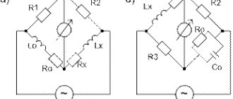
The image below shows two different illustrations of a Wheatstone bridge: Figure a) is a normal diamond image using a Wheatstone bridge; Figure b) shows an image of the same electrical circuit, but more understandable for a beginner.
The four branches of the bridge circuit are formed by resistances from R 1 to R 4. Corner points 2 and 3 indicate connections for the bridge excitation voltage V s . The bridge output voltage V0, that is, the measurement signal, is available at corner points 1 and 4.
There is no generally accepted rule for naming bridge components and connections. There are all sorts of notations in the popular literature, and this is reflected in the bridge equations. It is therefore important that the designations and indices used in the equations are taken into account along with their position in the bridge circuits, this will help to avoid confusion.
If the supply voltage V s is applied to the bridge supply points 2 and 3, then the supply voltage is divided into two halves of the bridge R 1, R 2 and R 4, R 3 as the ratio of the corresponding bridge resistances. , i.e. each half of the bridge forms a voltage divider.
The bridge may be unbalanced due to differences in voltages and electrical resistances across R 1, R 2 and R 3, R 4. This can be calculated as follows:
if the bridge is balanced and
where the bridge output voltage V 0 is zero.
For a given deformation, the resistance of the strain gauge changes by the amount ΔR. This gives us the following equation:
To measure strain, the resistances R 1 and R 2 in a Wheatstone bridge must be the same. The same applies to R 3 and R 4 .
With a few simplifications, the following equation can be derived:
At the last stage of the calculation, ΔR/R must be replaced by the following:
Here k is the coefficient k of the strain gauge, ε is the deformation. We get the following:
The equations assume that all resistances in the bridge change. Designations such as quarter bridge, half bridge, double quarter or diagonal bridge and full bridge are common.
Although the above-mentioned definitions such as “half-bridge” or “quarter-bridge” are used to designate such circuits, in fact they are not entirely correct. In fact, the circuit used for measurement is always complete and is formed entirely or partially by strain gauges. They are then supplemented by fixed resistors, which are built into the measuring instruments.
Weighing terminals typically meet very stringent accuracy requirements. Therefore, unlike experimental measuring instruments, weighing transducers should always have a full bridge circuit with active load cells on all four arms.
In case it is necessary to eliminate various interferences and factors interfering with the measurement, full-bridge or half-bridge circuits are used for load analysis. An important condition is a clear distinction between stresses and forces, such as compression or tension, as well as bending, shearing or twisting forces.
The table below shows the relationship between the position of the strain gauges, the type of bridge circuit used and the resulting bridge coefficient B for normal forces, bending moments, torque and temperature. The small tables provided for each example indicate the bridge coefficient B for each type of influence quantity. These equations are used to calculate the effective voltage from the output of the VO/VS bridge.
| Bridge configuration | Calculation | Measurement | Description | Advantages and disadvantages | |
| 1 | Measuring strain on a tension/compression bar Measuring strain on a bending beam | Simple quarter bridge Simple quarter bridge circuit with one active load cell | + Easy installation – Normal deformation and bending deformation are superimposed on each other – Temperature effects are not automatically compensated | ||
| 2 | Measuring strain on a tension/compression bar Measuring strain on a bending beam | Quarter Bridge Two quarter bridge circuits, one actively measures deformation, the other is mounted on a passive component made of the same material that does not undergo deformation. | + Temperature effects are well compensated – Normal deformation and bending deformation cannot be separated (flexural superposition) | ||
| 3 | Measuring strain on a tension/compression bar Measuring strain on a bending beam | Poisson half-bridge Two active load cells connected by a half-bridge, one of which is located at a 90° angle to the other | + Temperature effects are well compensated when the material is isotropic | ||
| 4 | Measuring the deformation of a bending beam | Half-bridge Two strain gauges are installed on opposite sides of the structure. | + Temperature effects are well compensated + Separation of normal and bending strain (only the bending effect is measured) | ||
| 5 | Measuring strain on a tension/compression bar | Diagonal bridge Two strain gauges are installed on opposite sides of the structure. | + Normal strain is measured independently of bending strain (bending excluded) | ||
| 6 | Measuring strain on a tension/compression bar Measuring strain on a bending beam | Full bridge 4 load cells are installed on one side of the structure as a full bridge. | + Temperature effects are well compensated + High output signal and excellent common mode rejection (CMR) – Normal deformation and bending deformation cannot be separated (bending superposition) | ||
| 7 | Measuring strain on a tension/compression bar | Diagonal bridge Two active load cells, two passive load cells | + Normal deformation is measured independently of bending deformation (bending excluded) + Temperature effects are well compensated | ||
| 8 | Measuring the deformation of a bending beam | Full Bridge Four active load cells connected as a full bridge | + Separation of normal and bending deformation (only the bending effect is measured) + High output signal and excellent common mode rejection (CMR) + Temperature effects are well compensated | ||
| 9 | Measuring strain on a tension/compression bar | Full bridge Four active load cells, two of which are rotated 90° | + Normal strain is measured independently of bending strain (bending excluded) + Temperature effects are well compensated + High output signal and excellent common mode rejection (CMR) | ||
| 10 | Measuring the deformation of a bending beam | Full bridge Four active load cells, two of which are rotated 90° | + Separation of normal and bending deformation (only the bending effect is measured) + High output signal and excellent common mode rejection (CMR) + Temperature effects are well compensated | ||
| 11 | Measuring the deformation of a bending beam | Full bridge Four active load cells, two of which are rotated 90° | + Separation of normal and bending deformation (only the bending effect is measured) + High output signal and excellent common mode rejection (CMR) + Temperature effects are well compensated | ||
| 12 | Measuring the deformation of a bending beam | Full Bridge Four active load cells connected as a full bridge | + Separation of normal and bending deformation (only the bending effect is measured) + Temperature effects are well compensated + High output signal and excellent common mode rejection (CMR) | ||
| 13 | Measuring torsional strain | Full Bridge Four load cells are installed, each at an angle of 45° to the main axis, as shown. | + High output signal and excellent common mode rejection (CMR) + Temperature effects are well compensated | ||
| 14 | Measuring torsional strain in limited installation space | Full Bridge Four load cells are mounted as a full bridge at a 45° angle and overlap each other (rosettes) | + High output signal and excellent common mode rejection (CMR) + Temperature effects are well compensated | ||
| 15 | Measuring torsional strain in limited installation space | Full Bridge Four load cells are mounted as a full bridge at a 45° angle and overlap each other (rosettes) | + High output signal and excellent common mode rejection (CMR) + Temperature effects are well compensated | ||
Examples 13, 14 and 15 assume a cylindrical shaft to measure torque. For reasons of symmetry, bending in the X and Y directions is allowed. The same conditions apply for bars with a square or rectangular cross-section.
Explanation of symbols:
| T | Temperature |
| Fn | Normal strength |
| M b | Bending moment |
| M bx , M – by user | Bending moment for X and Y directions |
| M d | Torque |
| εs | Apparent voltage |
| ε n | Normal voltage |
| ε b | Bending deformation |
| ε d | Torsional deformity |
| ε | Effective strain at the measuring point |
| ν | Poisson's ratio |
| Active load cell | |
| Load cell for temperature compensation | |
| Resistor or passive strain gauge |
Varieties
- Small resistances are measured using a Carey Fother device. You can find out the difference between the counteractions of large values.
- Another type is the Kelvin-Varley divider. Used in laboratory equipment. The maximum measuring ability recorded by this voltage divider reaches 1.0*10-7.
- The Kelvin bridge, which in some countries is called after Thomson, is intended for measuring unknown resistances of small values (less than 1 ohm). The principle of operation is similar to a single Winston bridge. The only difference is the presence of additional resistance, which reduces measurement errors that appear as a result of a voltage drop in one of the arms.
- Another type is the Maxwell bridge. Measures low-Q inductance of unknown magnitude.
Measuring bridge circuits
AC measuring bridges are divided into 2 groups: double and single. Single ones have 4 shoulders. In them, 3 branches create a circuit with 4 connection points.
There is an electromagnetic galvanometer in the diagonal of the bridge that shows balance. In the other diagonal of the bridge there is a constant power source. Measurements may have errors depending on their range. As the resistance increases, the sensitivity of the device decreases.
A double bridge is called a six-arm bridge. Its arms are the measured resistance (Rx), a resistor (Ro) and 2 pairs of additional resistors (Rl, R2, R3, R4).
Main technical characteristics of the MMV device:
5 ranges: 0.05-5 Ohm, 0.5-50 Ohm, 5-500 Ohm, 50-5000 Ohm, 500-50000 Ohm.
The indicator has the following five measurement ranges: from 0.05 to 5 Ohms; from 0.5 to 50 Ohm; from 5 to 500 Ohm; from 50 to 5000 Ohm; from 500 to 50000 Ohm.
The main error of the MMV indicator readings on the middle o scale of the slide chord does not exceed ±2.0% and on both sides of it to o and “20” does not exceed ±5.0% of the actual value of the measured resistance in the following switch positions: “xl”; "x10"; “x100”, in other cases the main error does not exceed ±15%. In the position of the multiplicity switch “x0.1” to o and “1”, the main error is not standardized. The settling time of the moving part of the galvanometer is no more than 4 s. The indicator position is horizontal.
Overall dimensions of the indicator are no more than 201 x 111 x 65 mm. The weight of the indicator without power supplies is no more than 1.1 kg.
Where is the Wheatstone measuring bridge used?
Measuring elements are used when working with metal cable lines. They allow you to neutralize extraneous influences for more efficient localization of defects. Highly accurate results are guaranteed within the range of measured values.
Using a Wheatstone bridge circuit, you can calculate the resistance of a changing element. The circuits are used in the construction of electronic scales, electronic thermometers and thermistors.
Among industrial designs, devices with manual equilibrium calibration are widely known:
- MMV – measures the resistance of a DC voltage conductor;
- P333 is a single bridge circuit, with the help of which a damaged section of the cable is identified.
General description of MMV DC Bridge
The portable linear MMV Winston bridge is designed for technical measurements of DC resistance.
Main technical characteristics of the MMV device:
5 ranges: 0.05-5 Ohm, 0.5-50 Ohm, 5-500 Ohm, 50-5000 Ohm, 500-50000 Ohm. Possible replacement: P3043, HN 2570
You can place an order for equipment either through our website or by phone. By ordering this product and coming to our office to pick it up yourself, you can save on delivery.
Accompanying documentation, operating instructions, user manual for MMV are located on our website etk-elcom.ru (www.etk-elcom.ru) in the “Technical Documentation” section.
If you have any questions, including about the price, do not hesitate to contact us.