Foreign designations of radio components
Go to domestic designations ▼
The international standard is IEEE 315. This list ▼ also includes designations that are not reflected in the standard, but are encountered in practice.
A — Separable assembly or sub-assembly (eg printed circuit assembly) — Separate module or device AE — Aerial — Antenna ANT — Antenna — Antenna AR — Amplifier (other than rotating), repeater — Amplifier, repeater AT — Attenuator, inductive termination, resistive termination - Attenuator, inductive termination, resistive termination B - Bead Ferrite - Ferrite filter B - Battery - Battery B - Motor - Electric motor BR - Bridge rectifier - Diode bridge BT - Battery - Battery BT - Photovoltaic transducer, solar cell - Photovoltaic converter, solar battery C - Capacitor - Capacitor CB - Circuit Board - Circuit board CB - Circuit breaker - Circuit breaker CN - Capacitor network - Capacitor assembly CN - Contact - Contact CP - Connector adapter, junction (coaxial or waveguide) - Adapter, connection (coaxial or waveguide) CR - Diode (TVS, thyristor, Zener, asymmetrical varistor, photodiode, stabistor, varactor overvoltage absorber) - Diode (avalanche diode, thyristor, zener diode, varistor with asymmetrical current-voltage characteristic, photodiode, stabistor, varactor, overvoltage absorber) CRT — Cathode ray tube — Cathode ray tube D — Diode (LED, TVS, thyristor, Zener, asymmetrical varistor, photodiode, stabistor, varactor overvoltage absorber) — Diode (LED, avalanche diode, thyristor, zener diode, varistor with asymmetric current-voltage characteristic, photodiode, stabistor, varactor, surge absorber) DC — Directional coupler — Directional coupler DL — Delay line — Delay line DS — Display, alphanumeric display device, annunciator, signal lamp — Display, alphanumeric indicator, indicator light, signal lamp DSP — Digital signal processor - Digital signal processor DSW - Dual in-line package switcher - DIP switch E - Electrical contact, antenna, binding post, cable termination, electrical contact brush, electrical shield, ferrite bead rings, hall element, insulator, lightning arrester, magnetic core, permanent magnet, short circuit (termination), telephone protector, vibrating reed, miscellaneous electrical part - Electrical contact, electrode, antenna, terminal, cable lug, electric brush, electrical screen, ferrite ring, hall effect element, insulator, spark gap, magnetic core, permanent magnet, jumper, loudspeaker, vibrating spring contact, other radio components EL - place of attachment of the radiator by soldering EP - Earphone - Headphones EQ - Equalizer - Equalizer EY - place of attachment of the electronic component, including the functional (current-carrying) ) pin F - Fuse - Fuse FB - Ferrite bead - Ferrite filter FD - Fiducial - Alignment point FEB - Ferrite bead - Ferrite filter FET - Field-effect transistor - Field-effect transistor FH - Fuse holder - fuse holder FL - Filter - Filter G - Generator or oscillator, electronic chopper, interrupter vibrator, rotating amplifier, telephone magneto - Electric generator or oscillator, electronic chopper, vibration converter, electric machine amplifier, telephone inductor GDT - Gas-discharge lamp - Gas-discharge lamp GN - General network - General network GND - Ground - “Ground”, common wire (usually, minus power) GR - Through contact (hollow rivet) GT - Single pin contact H - Hardware, eg, screws, nuts, washers - Fastening elements (screws, nuts, washers) HP - Hydraulic part — Hydraulic part HR — Heater, heating lamp, heating resistor, infrared lamp, thermomechanical transducer — Heating element, heating lamp, heating resistor, infrared lamp, thermomechanical transducer HS — Handset, operator's set — Handset, telephone headset HT — Earphone — Headset telephone, headphones HY - Circulator or directional coupler - Circulator or directional coupler I - Lamp - Incandescent lamp IC - Integrated Circuit - Microcircuit, integrated circuit J - Jack, Receptacle, Terminal Strip, connector - Socket, socket, cartridge, terminal block, connector J — Wire link, jumper — Jumper J — Jumper chip — Zero resistance resistor (jumper or SMD fuse) JFET — Junction gate field-effect transistor — Unijunction field-effect transistor JP — Jumper (Link) — Jumper K — Relay, contactor — Relay, contactor, electromagnetic starter L - Inductor, choke, electrical solenoid, field winding, generator field, lamp ballast, motor field, reactor - Inductor, inductor, solenoid, electromagnet winding, generator field winding, inductive ballast, motor field winding, reluctance coil LA - Lightning arrester - Lightning protection LCD - Liquid-crystal display - LCD display LDR - Light Dependent Resistor, - Photoresistor LED - Light-emitting diode - LED LS - Loudspeaker or buzzer, audible alarm, electric bell, electric horn, siren, telephone ringer, telephone sounder - Loudspeaker or buzzer, sound alarm, electric bell, howler, siren, telephone call, telephone capsule M - Motor - Electric motor M - Meter, electric timer, electrical counter, oscilloscope, position indicator, thermometer - Meter (generalized) , electric timer, electric meter, oscilloscope, position sensor, thermometer MCB - Miniature circuit breaker - Miniature circuit breaker MG - Dynamotor, motor-generator - Dynamotor, motor-generator MIC - Microphone - Microphone MK - Microphone - Microphone MOSFET - Metal-oxide-semiconductor field-effect transistor - MOS transistor MOV - Metal-oxide varistor MP - Mechanical part (including screws and fasteners) MT - Accelerometer - Accelerometer MV - Varistor N - Neon Lamp - Neon lamp NE - Neon Lamp - Neon lamp NT - Thermistor NTC - Negative Temperature Coefficient - Thermistor with negative temperature coefficient of resistance OP - Operational amplifier - Operational amplifier P - Plug - Plug, plug, connector P - Single pin PC - Photocell — Photocell PCB — Printed circuit board — Printed circuit board PH — Earphone — Headphones PL — PLC connector — Programmable logic controller — Programmable logic controller PS — Power supply, rectifier (complete power-supply assembly) — Secondary power supply, rectifier PTC and PTH - Positive Temperature Coefficient - PTC (thermistor with a positive temperature coefficient of resistance) PU - Pickup, head - Pickup, transmitting television tube, magnetic head Q - Transistor, semiconductor controlled rectifier, semiconductor controlled switch, phototransistor (3 terminal), thyratron ( semiconductor device) - Transistor, semiconductor converter, semiconductor switch, three-pin phototransistor, semiconductor thyratron R - Resistor, function potentiometer, instrument shunt, magnetoresistor, potentiometer, relay shunt, rheostat - Resistor, functional potentiometer, measuring shunt, magnetoresistor, potentiometer, winding shunt relay, rheostat RE — Radio receiver — Radio receiving device RFC — Radio frequency choke — High-frequency choke RJ — Resistor Joint — Resistor assembly RLA — Relay — Relay RN — Resistor Network — Resistor assembly RT — Thermistor, ballast lamp, ballast tube, current-regulating resistor, thermal resistor - Thermistor, thermistor, electrovacuum current stabilizer, gas-discharge zener diode, current-regulating resistor, thermistor RV - Varistor, symmetrical varistor, voltage-sensitive resistor - Varistor, varistor with symmetrical current-voltage, voltage-controlled resistor RY - Relay - Relay S - Switch , contactor (manually, mechanically or thermally operated), flasher (circuit interrupter), governor (electrical contact type), telegraph key, telephone dial, thermal cutout (circuit interrupter) (not visual), thermostat - Switch, switch, button, starter (manual, mechanical, thermal), circuit breaker, contact type regulator, telegraph key, dialer, thermal switch, thermal relay S - SCR connector - Silicon controlled rectifier - Unidirectional controlled thyristor SG - Spark gap - Arrester SP - Test point SPK - Speaker - Loudspeaker SQ - Electric squib - Electric igniter SR - Rotating contact, slip ring - Rotating contact, slip ring SUS - Silicon unilateral switch - Threshold SCR SW - Switch - Switch, switch, button T - Transformer - Transformer TB - Connecting strip, test block - Terminal block, test block TC — Thermocouple — Thermocouple TFT — Thin-film-transistor display — TFT display TH — Thermistor — Thermistor, thermistor TP — Test point — Test (measuring) point TR — Transistor — Transistor TR — Radio transmitter — Radio transmitter TUN - Tuner - Tuner U - Integrated Circuit - Microcircuit, integrated circuit U - Photon-coupled isolator - Optocoupler V - Vacuum tube, valve, ionization chamber, klystron, magnetron, phototube, resonator tube (cavity type), solion, thyratron ( electron tube), traveling-wave tube, voltage regulator (electron tube) - Radio tube, ionization chamber, klystron, magnetron, vacuum photocell, cavity vacuum resonator, chemotron sensor, thyratron (radio tube), traveling wave tube, voltage regulator (radio tube) VC — Variable capacitor — Variable capacitor VDR — Voltage Dependent Resistor — Varistor; voltage controlled resistor VFD - Vacuum fluorescent display - Vacuum fluorescent indicator VLSI - Very-large-scale integration - VLSI - ultra-large-scale integrated circuit VR - Variable resistor (potentiometer or rheostat) VR - Voltage regulator - Voltage regulator (stabilizer) VT — Voltage transformer — Voltage transformer W — Wire, bus bar, cable, waveguide — Wire, jumper, bus, cable, waveguide WT — Wiring tiepoint — Junction point X — Solar cell — Solar cell X — Other converters — Converters not included in other categories X — Ceramic resonator — Ceramic resonator, quartz oscillator X_ — Socket connector for another item — Connector for elements. The second letter corresponds to the element being connected XA - Socket connector for printed circuit assembly connector - Connector for printed circuit boards XDS - Socket connector for light socket - Connector for socket XF - Socket connector for fuse holder - Connector for fuse XL - Lampholder - Lamp holder XMER - Transformer — Transformer XTAL — Crystal — Quartz oscillator XU — Socket connector for integrated circuit connector — Connector for microcircuit XV — Socket connector for vacuum tube socket — Connector for radio tube Y — Crystal or oscillator — Quartz resonator or oscillator Z — Zener diode — Zener diode Z — Balun, coupled tunable resonator, directional phase shifter (non-reciprocal), gyrator, mode suppressor, multistub tuner, phase shifter, resonator (tuned cavity) type, quartz piezo filter. ZD — Zener Diode — Zener diode ZSCT — Zero sequence current transformer, also called a window-type current transformer — Zero sequence current transformer, current transformer with an opening for the primary circuit
Other items
All radio components are connected to each other by conductors. In the diagram they are depicted as straight lines and drawn strictly horizontally and vertically. If the conductors have an electrical connection when crossing each other, then a dot is placed at this place. In Soviet and American diagrams, to show that the conductors are not connected, a semicircle is placed at the intersection.
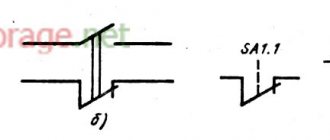
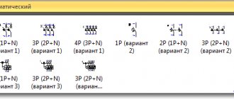
To designate variable capacitors, an arrow is used; it crosses out the capacitor diagonally. In trimmers, a T-shaped sign is used instead of an arrow. Varicond - a capacitor that changes capacitance depending on the applied voltage, is drawn like an alternating one, but the arrow is replaced by a short straight line, next to which there is the letter u. The capacitance is shown with a number and a microFarad (microFarad) is placed next to it. If the capacity is smaller, the letter code is omitted.
Another element that no electrical circuit can do without is a resistor. Indicated in the diagram as a rectangle. To show that the resistor is variable, an arrow is drawn on top. It can be connected either to one of the pins, or be a separate pin. For trimmers, a sign in the form of the letter t is used. As a rule, its resistance is indicated next to the resistor.
Symbols in the form of dashes can be used to indicate the power of fixed resistors. A power of 0.05 W is indicated by three oblique, 0.125 W - two oblique, 0.25 W - one oblique, 0.5 W - one longitudinal. High power is shown in Roman numerals. Due to the diversity, it is impossible to describe all the designations of electronic components on the diagram. To identify a particular radio element, use reference books.
Domestic designations of radio components
Go to foreign designations ▲
The letter designations of electronic components on domestic circuits are regulated by GOST 2.710-81 “Alphanumeric designations in electrical circuits.”
A - Devices AA - Current regulator AB - Actuator drives AC - AVR device AF - Frequency regulator AK - Protection relay device (set) AKB - Blocking device type KRB AKS - Automatic reclosure device AKV - Complete device for longitudinal differential protection of power lines AKZ - Complete relay device resistance AR - Complete breaker failure relay device AV - Voltage regulation device AW - Power regulator B - Converters of non-electrical quantities into electrical ones (except for generators and power supplies) or vice versa, analogue or multi-digit converters or sensors for indicating or measuring BA - Loudspeaker BB - Magnetostrictive element BC — Selsyn sensor BD — Ionizing radiation detector BE — Selsyn receiver BF — Telephone (capsule) BK — Thermal sensor BL — Photocell BM — Microphone BP — Pressure sensor BQ — Piezoelectric element BR — Speed sensor (tachogenerator) BS — Sound pickup BT — Temperature sensor BV — Speed sensor BVA — Reactive volt-amp-hour meter BW — Active watt-hour meter C — Capacitors CB — Capacitor power unit CG — Capacitor charging unit D — Integrated circuits, microassemblies DA — Analog integrated circuit DD — Integrated circuit, digital, logical element DS — Information storage devices DT — Delay device E — Various elements EK — Heating element EL — Lighting lamp ET — Squib F — Surge arresters, fuses, protective devices FA — Discrete instantaneous current protection element FP — Discrete inertial current protection element actions FU - Fusible fuse FV - Discrete voltage protection element, arrester G - Generators, power supplies, quartz oscillators GB - Battery GC - Synchronous compensator GE - Generator exciter GEA - Sub-exciter (auxiliary exciter) H - Indicating and signaling devices HA - Device sound alarm HG - Symbolic indicator HL - Light signaling device HLA - Light display HLG - Alarm lamp with a green lens HLR - Alarm lamp with a red lens HLW - Alarm lamp with a white lens HY - Semiconductor indicator K - Relays, contactors, starters KA - Relay current KA0 — Zero-sequence current relay, zero-sequence current protection KAT — Current relay with saturable transformer, current protection with time delay KAW — Current relay with braking KAZ — Filter current relay KB — Blocking relay KBS — Multi-closing blocking relay KCC — Relay "turn on" commands KCT - Relay for "turn off" commands KF - Frequency relay KH - Indicative relay KHA - Pulse signaling relay KK - Electrothermal relay KLP - Repeating pressure relay KM - Contactor, magnetic starter KQ - Switch position fixing relay KQC - Position relay " "On" KQQ - Relay for fixing the switching command KQS - Relay for fixing the position of the disconnector KQT - Relay for the "Off" position KS - Control relay KSG - Gas relay KSH - Jet (pressure) relay KSS - Synchronism control relay KSV - Voltage control relay KT - Time relay KV - Voltage relay KVZ - Filter - voltage relay KW - Power relay KZ - Resistance relay L - Inductors, chokes LG - Reactor LL - Fluorescent lighting choke LR - Generator excitation winding M - Motors P - Instruments, measuring equipment PA - Ammeter PC — Electromechanical pulse counter PF — Frequency meter PG — Oscilloscope PHE — Position indicator PI — Active energy meter PK — Reactive energy meter PR — Ohmmeter PS — Recording device PT — Clock, operating time meter PV — Voltmeter PVA — Varmeter PW — Wattmeter Q — Switches and disconnectors in power circuits QF - Automatic switch QK - Short circuit QN - Short circuit QR - Separator QS - Disconnector QW - Load switch R - Resistors RK - Thermistor RP - Potentiometer RR - Rheostat RS - Measuring shunt RU - Varistor S - Switching devices in circuits control, signaling and measuring SA - Switch or switch SAB - Switch, key in blocking circuits SAC - Mode switch SB - Push-button switch SC - Switch SF - Automatic switch SK - Temperature-triggered switch SL - Level-triggered switch SN - Switch measurements SP — Pressure-triggered switch SQ — Limit switch SQ — Position-triggered switch SQA — Auxiliary contact that detects emergency shutdown of the circuit breaker SQC — Auxiliary contact in the closing electromagnet circuit SQK — Auxiliary contact that closes when the circuit breaker is turned off SQM — Auxiliary contact that closes when the switch is turned on (starting the ABM spring winding motor) SQT — Auxiliary contact in the trip electromagnet circuit SQY — Auxiliary spring ready contact that controls the ABM spring winding motor SR — Speed-activated switch SS — Synchronization switch SX — Trim operational T - Transformers, autotransformers TA - Current transformer TAN - Zero sequence current transformer TAV - Transreactor TL - Intermediate transformer TLV - Voltage take-off transformer TS - Electromagnetic stabilizer TS - Electromagnetic stabilizer TUV - Regulating transformer TV - Voltage transformer U - Converters of electrical quantities in electrical, communication devices UA — Current converter UB — Modulator UF — Frequency converter UI — Discriminator UR — Demodulator UV — Voltage converter, phase regulator UZ — Frequency converter, inverter, frequency generator, rectifier V — Electrovacuum, semiconductor devices VD — Diode, zener diode VL — Electrovacuum device VS — Thyristor VT — Transistor W — Microwave lines and elements, antennas WA — Antenna WE — Coupler WK — Short circuit WS — Valve WT — Transformer, inhomogeneity, phase shifter WU — Attenuator X — Contact connections XA — Current collector, sliding contact XB — Jumper XG — Test clamp XN — Non-separable connection XP — Pin XS — Socket XT — Demountable connection XW — High-frequency connector Y — Mechanical devices with an electromagnetic drive YA — Electromagnet YAB — Electromagnetic blocking lock YAC — Switching electromagnet in the air circuit breaker drive (lightweight) drive), switch-on contactor YAT - Switch-off electromagnet (switch-off solenoid) YB - Brake with electromagnetic drive YC - Clutch with electromagnetic drive YH - Electromagnetic cartridge or plate YMC - Switch-on electromagnet in the oil circuit breaker drive (heavy drive) Z - Terminal devices, filters, limiters ZA - Current filter ZF - Frequency filter ZL - Limiter ZQ - Quartz filter ZV - Voltage filter
Letter codes of the functional purpose of a radio-electronic device or element A - Auxiliary C - Counting D - Differentiating F - Protective G - Testing H - Signal I - Integrating M - Main N - Measuring P - Proportional Q - State (start, stop, limitation) R - Return, reset S - Storage, recording t - Synchronizing, delaying V - Speed (acceleration, deceleration) W - Adding X - Multiplying Y - Analog Z - Digital
Tags: Components, designations, Radio components
Discussion: 34 comments
- Vladimir:
May 1, 2022 at 09:02Normal garland. Here's more about it.
Answer
- Vladimir:
May 1, 2022 at 09:01
Found
Answer
← Previous comments
Capacitors
Next we take capacitors. They have slightly different markings. On modern capacitors there is only digital marking, so we do not pay attention to all letters except “p”, “n”; all extraneous letters usually indicate tolerance, heat resistance, and so on. They usually have a code marking of 3 digits. We leave the first three as is, and the third shows the number of zeros, and we write down these zeros, after which the capacity is obtained in picofarads.
But there are also ones with a quantity of less than 3 digits (two or one). This means the capacity is in the picofarads already indicated to us. Example:
- 3 = 3 picofarads
- 47 = 47 picofarads
Here is a photo:
There is a capacity of 18 picofarads.
If there are letters "n" or "p", then the capacity is in picofards or nanofarads, for example:
- Letter "n" - nanofarads
- Letter "p" - picofarads
The first (large) one says “2n7” - in this case, like the 2.7 nanofarad resistor. The second capacitor says 58n, that is, its capacity is 58 nanofarads. But if you still don’t understand this, it’s better to buy a multimeter, for example UT-61, it has a function for measuring capacitance. There is a special connector where a capacitor is inserted and under it you need to select the required measurement range (in picofarads, nanofarads, microfarads). This multimeter has a capacitance measured up to 20 microfarads.
Features of reading circuits
In circuit diagrams, conductors (or tracks) are indicated by lines.
This designates conductors that intersect, but they do not have a common connection and are not electrically connected to each other.
And this is what they look like if there is a connection between them. The black dot is a node in the circuit. A node is a connection of several conductors or parts together. They are electrically connected to each other.
Common point
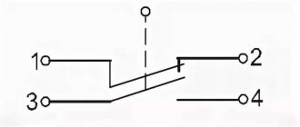
Beginner radio amateurs often have a question: what is this symbol on the diagram?
This is the common point (GND, ground). Previously, it was called the common wire. This is how a single power wire is designated. Usually this is a minus of nutrition. Previously, in the diagrams they could make the common wire and the power plus. In this case, the diagram without a common point would look like this:
A common point with unipolar power supply looks visually better and more compact than if you simply make a single line between them.
It is also called a common point because any other points on the diagrams can be measured relative to it. For example, place the multimeter probe on a common point, and with the second probe you can check any part of the circuit in the diagram.
Why can it be called ground (GND)? Previously, the chassis of the device body could be used as a common wire. This has caused confusion between grounding and earth. It is interpreted in the context of the schema. The circuit that was discussed above - the common point (ground) is simply a minus of the power supply. Another thing is bipolar current sources and grounding.
Bipolar power supply and common point
In a bipolar supply, the common point is the middle contact between plus and minus.
Grounding
An example of grounding would be a filter in computer power supplies.
From the capacitor filter, noise goes to the power supply housing. This is grounding. And from the power supply they must go into the outlet if you have a ground connection, otherwise the body of the power supply itself may be energized. The currents there are not large, they are not life-threatening. This is done to reduce impulse noise in the power supply and safety.
Sometimes in power supplies, instead of the housing, noise from the capacitor goes to a common point. It all depends on the design and circuitry. In this case, there will be more interference than with grounding.
In general, there are different grounding connections on the diagrams. For example, in digital technology, analog ground is separated from digital ground. so as not to disrupt the operating modes of the circuit. Pulse noise can affect the analog part of the circuit.
Main types and sizes of SMD devices
Housings of components for microelectronics that have the same nominal values may differ from each other in dimensions. Their dimensions are determined primarily by the standard size of each. For example: resistors are designated by standard sizes from “0201” to “2512”. These 4 digits in the SMD component marking indicate a coding that indicates the length and width of the device in inch measurements. In the table provided, typical dimensions are also indicated in mm.
Marking of SMD components - resistors
| Square Chip Resistors and Ceramic Capacitors | |||||
| Standard size | L, mm (inch) | W, mm (inch) | H, mm (inch) | A, mm | W |
| 0201 | 0.6 (0.02) | 0.3 (0.01) | 0.23 (0.01) | 0.13 | 1/20 |
| 0402 | 1.0 (0.04) | 0.5 (0.01) | 0.35 (0.014) | 0.25 | 1/16 |
| 0603 | 1.6 (0.06) | 0.8 (0.03) | 0.45 (0.018) | 0.3 | 1/10 |
| 0805 | 2.0 (0.08) | 1.2 (0.05) | 0.4 (0.018) | 0.4 | 1/8 |
| 1206 | 3.2 (0.12) | 1.6 (0.06) | 0.5 (0.022) | 0.5 | 1/4 |
| 1210 | 5.0 (0.12) | 2.5 (0.10) | 0.55 (0.022) | 0.5 | 1/2 |
| 1218 | 5.0 (0.12) | 2.5 (0.18) | 0.55 (0.022) | 0.5 | 1 |
| 2010 | 5.0 (0.20) | 2.5 (0.10) | 0.55 (0.024) | 0.5 | 3/4 |
| 2512 | 6.35 (0.25) | 3.2 (0.12) | 0.55 (0.024) | 0.5 | 1 |
| Cylindrical chip resistors and diodes | |||||
| Standard size | Ø, mm (inch) | L, mm (inch) | W | ||
| 0102 | 1.1 (0.01) | 2.2 (0.02) | 1/4 | ||
| 0204 | 1.4 (0.02) | 3.6 (0.04) | 1/2 | ||
| 0207 | 2.2 (0.02) | 5.8 (0.07) | 1 |
SMD capacitors
Capacitors made of ceramic are the same size as resistors; as for tantalum capacitors, they are determined according to their own standard size scale:
| Tantalum capacitors | |||||
| Standard size | L, mm (inch) | W, mm (inch) | T, mm (inch) | B, mm | A, mm |
| A | 3.2 (0.126) | 1.6 (0.063) | 1.6 (0.063) | 1.2 | 0.8 |
| B | 3.5 (0.138) | 2.8 (0.110) | 1.9 (0.075) | 2.2 | 0.8 |
| C | 6.0 (0.236) | 3.2 (0.126) | 2.5 (0.098) | 2.2 | 1.3 |
| D | 7.3 (0.287) | 4.3 (0.170) | 2.8 (0.110) | 2.4 | 1.3 |
| E | 7.3 (0.287) | 4.3 (0.170) | 4.0 (0.158) | 2.4 | 1.2 |
SMD Inductors and Chokes
Inductive coils can be made in various housing configurations, but their value is also indicated based on the standard sizes. This principle of SMD marking and decoding of codes makes it possible to significantly simplify the installation of elements on the board in automatic mode, and for the radio amateur to navigate more freely.
dr>
Winding components such as coils, transformers and others, which in most cases we make ourselves, may simply not fit on the board. Therefore, such products are also available in compact versions that can be installed on a board.
To determine which coil your project requires, it is best to use the catalog and select the required option according to the standard size there. Typical sizes are determined using a code marking marked with 4 numbers (0805). Where "08" is the length and "05" is the width in inches. The actual dimensions of such an SMD component will be 0.08x0.05 inches.
Diodes and Zener diodes in SMD housing
As for diodes, they are also available in both cylindrical and polyhedron-shaped cases. The typical dimensions of these components are set identically to inductive coils, resistors and capacitors.
| Diodes, Zener diodes, capacitors, resistors | |||||
| Type of shell | L* (mm) | D* (mm) | F* (mm) | S* (mm) | Note |
| DO-213AA (SOD80) | 3.5 | 1.65 | 048 | 0.03 | JEDEC |
| DO-213AB (MELF) | 5.0 | 2.52 | 0.48 | 0.03 | JEDEC |
| DO-213AC | 3.45 | 1.4 | 0.42 | — | JEDEC |
| ERD03LL | 1.6 | 1.0 | 0.2 | 0.05 | PANASONIC |
| ER021L | 2.0 | 1.25 | 0.3 | 0.07 | PANASONIC |
| ERSM | 5.9 | 2.2 | 0.6 | 0.15 | PANASONIC, GOST R1-11 |
| MELF | 5.0 | 2.5 | 0.5 | 0.1 | CENTS |
| SOD80 (miniMELF) | 3.5 | 1.6 | 0.3 | 0.075 | PHILIPS |
| SOD80C | 3.6 | 1.52 | 0.3 | 0.075 | PHILIPS |
| SOD87 | 3.5 | 2.05 | 0.3 | 0.075 | PHILIPS |
Transistors in SMD housing
SMD transistors are made in packages that correspond to their maximum power. The cases of these semiconductor elements can be symbolically divided into two types: SOT and DPAK.
Marking of SMD components
Labeling electronic devices in modern technology already requires professional knowledge, and it’s so simple that it’s hard to understand at first glance, especially for a novice radio amateur. In comparison with parts produced in the Soviet Union, where the marking of the nominal value and type of device was applied in text form, now this is simply a soldering tool meta. There was no need to keep piles of reference literature on hand to determine the purpose and parameters of a particular device.
However, technological processes in industry do not stand still and production automation determines its own rules. It is SMD parts that play the main role in surface mounting, and the robot does not care about marking the parts inserted into the machine; what is placed there, it solders. The marking is needed by the specialist who services this robot.
Download a program to decipher the designation of SMD parts
Standard sizes of SMD components
Chip components of the same denomination may have different dimensions. The dimensions of an SMD component are determined by its “standard size”. For example, chip resistors have standard sizes from “0201” to “2512”. These four digits encode the width and length of the chip resistor in inches. In the tables below you can see the standard sizes in millimeters.
smd resistors
| Square Chip Resistors and Ceramic Capacitors | |||||
| Standard size | L, mm (inch) | W, mm (inch) | H, mm (inch) | A, mm | W |
| 0201 | 0.6 (0.02) | 0.3 (0.01) | 0.23 (0.01) | 0.13 | 1/20 |
| 0402 | 1.0 (0.04) | 0.5 (0.01) | 0.35 (0.014) | 0.25 | 1/16 |
| 0603 | 1.6 (0.06) | 0.8 (0.03) | 0.45 (0.018) | 0.3 | 1/10 |
| 0805 | 2.0 (0.08) | 1.2 (0.05) | 0.4 (0.018) | 0.4 | 1/8 |
| 1206 | 3.2 (0.12) | 1.6 (0.06) | 0.5 (0.022) | 0.5 | 1/4 |
| 1210 | 5.0 (0.12) | 2.5 (0.10) | 0.55 (0.022) | 0.5 | 1/2 |
| 1218 | 5.0 (0.12) | 2.5 (0.18) | 0.55 (0.022) | 0.5 | 1 |
| 2010 | 5.0 (0.20) | 2.5 (0.10) | 0.55 (0.024) | 0.5 | 3/4 |
| 2512 | 6.35 (0.25) | 3.2 (0.12) | 0.55 (0.024) | 0.5 | 1 |
| Cylindrical chip resistors and diodes | |||||
| Standard size | Ø, mm (inch) | L, mm (inch) | W | ||
| 0102 | 1.1 (0.01) | 2.2 (0.02) | 1/4 | ||
| 0204 | 1.4 (0.02) | 3.6 (0.04) | 1/2 | ||
| 0207 | 2.2 (0.02) | 5.8 (0.07) | 1 |
smd capacitors
Ceramic chip capacitors are the same size as chip resistors, but tantalum chip capacitors have their own size system:
| Tantalum capacitors | |||||
| Standard size | L, mm (inch) | W, mm (inch) | T, mm (inch) | B, mm | A, mm |
| A | 3.2 (0.126) | 1.6 (0.063) | 1.6 (0.063) | 1.2 | 0.8 |
| B | 3.5 (0.138) | 2.8 (0.110) | 1.9 (0.075) | 2.2 | 0.8 |
| C | 6.0 (0.236) | 3.2 (0.126) | 2.5 (0.098) | 2.2 | 1.3 |
| D | 7.3 (0.287) | 4.3 (0.170) | 2.8 (0.110) | 2.4 | 1.3 |
| E | 7.3 (0.287) | 4.3 (0.170) | 4.0 (0.158) | 2.4 | 1.2 |
smd inductors and chokes
Inductors are found in many types of housings, but the housings are subject to the same size law. This makes automatic installation easier. And it makes it easier for us, radio amateurs, to navigate.
All kinds of coils, chokes and transformers are called “winding products”. Usually we wind them ourselves, but sometimes you can buy ready-made products. Moreover, if SMD options are required, which come with many bonuses: magnetic shielding of the housing, compactness, closed or open housing, high quality factor, electromagnetic shielding, wide range of operating temperatures.
It is better to select the required coil according to catalogs and the required standard size. Standard sizes, as for chip resistors, are specified using a four-number code (0805). In this case, “08” indicates the length, and “05” the width in inches. The actual size of such an SMD component will be 0.08x0.05 inches.
smd diodes and zener diodes
Diodes can be either in cylindrical cases or in cases in the form of small parallelipipeds. Cylindrical diode packages are most often represented by MiniMELF (SOD80 / DO213AA / LL34) or MELF (DO213AB / LL41) packages. Their standard sizes are set in the same way as for coils, resistors, and capacitors.
| Diodes, Zener diodes, capacitors, resistors | |||||
| Type of shell | L* (mm) | D* (mm) | F* (mm) | S* (mm) | Note |
| DO-213AA (SOD80) | 3.5 | 1.65 | 048 | 0.03 | JEDEC |
| DO-213AB (MELF) | 5.0 | 2.52 | 0.48 | 0.03 | JEDEC |
| DO-213AC | 3.45 | 1.4 | 0.42 | — | JEDEC |
| ERD03LL | 1.6 | 1.0 | 0.2 | 0.05 | PANASONIC |
| ER021L | 2.0 | 1.25 | 0.3 | 0.07 | PANASONIC |
| ERSM | 5.9 | 2.2 | 0.6 | 0.15 | PANASONIC, GOST R1-11 |
| MELF | 5.0 | 2.5 | 0.5 | 0.1 | CENTS |
| SOD80 (miniMELF) | 3.5 | 1.6 | 0.3 | 0.075 | PHILIPS |
| SOD80C | 3.6 | 1.52 | 0.3 | 0.075 | PHILIPS |
| SOD87 | 3.5 | 2.05 | 0.3 | 0.075 | PHILIPS |
smd transistors
Surface mount transistors can also be of low, medium and high power. They also have matching housings. Transistor cases can be divided into two groups: SOT, DPAK.
I would like to draw your attention to the fact that such packages may also contain assemblies of several components, not just transistors. For example, diode assemblies
Other items
All radio components are connected to each other by conductors. In the diagram they are depicted as straight lines and drawn strictly horizontally and vertically. If the conductors have an electrical connection when crossing each other, then a dot is placed at this place. In Soviet and American diagrams, to show that the conductors are not connected, a semicircle is placed at the intersection.
To designate variable capacitors, an arrow is used; it crosses out the capacitor diagonally. In trimmers, a T-shaped sign is used instead of an arrow. Varicond - a capacitor that changes capacitance depending on the applied voltage, is drawn like an alternating one, but the arrow is replaced by a short straight line, next to which there is the letter u. The capacitance is shown with a number and a microFarad (microFarad) is placed next to it. If the capacity is smaller, the letter code is omitted.
Another element that no electrical circuit can do without is a resistor. Indicated in the diagram as a rectangle. To show that the resistor is variable, an arrow is drawn on top. It can be connected either to one of the pins, or be a separate pin. For trimmers, a sign in the form of the letter t is used. As a rule, its resistance is indicated next to the resistor.
Symbols in the form of dashes can be used to indicate the power of fixed resistors. A power of 0.05 W is indicated by three oblique, 0.125 W - two oblique, 0.25 W - one oblique, 0.5 W - one longitudinal. High power is shown in Roman numerals. Due to the diversity, it is impossible to describe all the designations of electronic components on the diagram. To identify a particular radio element, use reference books.
Tags: , , automatic, ampere, antenna, beat, sconce, vago, varistor, view, switch, generator, house, , capacity, sign, like, capacitor, , magnet, magnetic, marking, installation, power, multimeter, voltage, nominal, num, oscilloscope, variable, constant, rule, principle, wire, project, start, , size, resistor, relay, repair, row, light, LED, connection, resistance, zener diode, circuit, ten, type, current, transistor , transformer, three-phase, , smart, installation, filter, photo, shield
Classification of radioelements
Systematization of electronic components is necessary so that a radio technician and electronics engineer can freely navigate the selection of radio components for the creation and repair of circuit boards for radio devices. The classification of names and types of radio components is carried out in three directions:
- CVC;
- installation method;
- appointment.
CVC
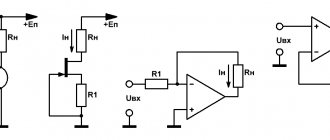
The three-letter abbreviation VAC stands for current-voltage characteristic. The current-voltage characteristic reflects the dependence of the current on the voltage flowing in any radio component. The characteristics appear in the form of graphs, where current values are plotted along the ordinate, and voltage values are noted along the abscissa. Based on the shape of the graph, radio components are divided into passive and active elements.
Passive
Radio components whose characteristics look like a straight line are called linear or passive radio elements. Passive parts include:
- resistors (resistance);
- capacitors (capacities);
- chokes;
- relays and solenoids;
- inductive coils;
- transformers;
- quartz (piezoelectric) resonators.
Active
Elements with nonlinear characteristics include:
- transistors;
- thyristors and triacs;
- diodes and zener diodes;
- photovoltaic cells.
The characteristics expressed on the graphs by a curved function refer to nonlinear radioelements.
I-V curves of linear and nonlinear radio components
Installation method
According to the installation method they are divided into three
- installation by volumetric soldering;
- surface mounting on printed circuit boards;
- connections using connectors and sockets.
Purpose
According to their purpose, radioelements can be divided into several groups:
- functional parts fixed on boards (the above components);
- display devices, these include various displays, indicators, etc.;
- acoustic devices (microphones, speakers);
- vacuum gas discharge: cathode ray tube, octodes, traveling and backward wave lamps, LEDs and LCD screens;
- thermoelectric parts – thermocouples, thermistors.
This is interesting: Scheme for electrification of cabins and construction trailers - we explain in detail
Permanent capacitors
These elements have differences in design, as well as in the materials from which they are made. The most popular types of dielectrics can be distinguished:
- Air.
- Mica.
- Ceramics.
But this applies exclusively to non-polar elements. There are also electrolytic capacitors (polar). It is these elements that have very large capacities - ranging from tenths of microfarads to several thousand. In addition to the capacity, such elements have one more parameter - the maximum voltage value at which its use is allowed. These parameters are written on the diagrams and on the capacitor housings.
Permanent capacitors
These elements have differences in design, as well as in the materials from which they are made. The most popular types of dielectrics can be distinguished:
But this applies exclusively to non-polar elements. There are also electrolytic capacitors (polar). It is these elements that have very large capacities - ranging from tenths of microfarads to several thousand. In addition to the capacity, such elements have one more parameter - the maximum voltage value at which its use is allowed. These parameters are written on the diagrams and on the capacitor housings.
Semiconductors
A standard semiconductor diode consists of two terminals and one rectifying electrical junction. All elements of the system are combined in a common housing made of ceramic, glass, metal or plastic. One part of the crystal is called the emitter, due to the high concentration of impurities, and the other part, with a low concentration, is called the base. The marking of semiconductors on the diagrams reflects their design features and technical characteristics.
Germanium or silicon is used to make semiconductors. In the first case, it is possible to achieve a higher transmission coefficient. Elements made of germanium are characterized by increased conductivity, for which even a low voltage is sufficient.
Depending on the design, semiconductors can be point or planar, and according to technological characteristics they can be rectifier, pulse or universal.
Main types of SMD components
Let's look at the main SMD elements used in our modern devices. Resistors, capacitors, low-value inductors, fuses, diodes and other components look like ordinary small rectangles, or rather, parallelepipeds))
On boards without a circuit, it is impossible to know whether it is a resistor, a capacitor, or even a coil. The Chinese mark as they please. On large SMD elements, they still put a code or numbers to determine their identity and value. In the photo below these elements are marked in a red rectangle. Without a diagram, it is impossible to say what type of radio elements they belong to, as well as their rating.
The standard sizes of SMD components may be different. Here is a description of the standard sizes for resistors and capacitors. Here, for example, is a yellow rectangular SMD capacitor. They are also called tantalum or simply tantalum:
And this is what SMD transistors look like:
There are also these types of SMD transistors:
Inductors, which have a high rating, in SMD version look like this:
And of course, how can we live without microcircuits in our age of microelectronics! There are many SMD types of chip packages, but I divide them mainly into two groups:
1) Microcircuits in which the pins are parallel to the printed circuit board and are located on both sides or along the perimeter.
2) Microcircuits in which the pins are located under the microcircuit itself. This is a special class of microcircuits called BGA (from the English Ball grid array
- an array of balls). The terminals of such microcircuits are simple solder balls of the same size.
The photo below shows a BGA chip and its reverse side, consisting of ball pins.
BGA chips are convenient for manufacturers because they greatly save space on the printed circuit board, because there can be thousands of such balls under any BGA chip. This makes life much easier for manufacturers, but does not make life any easier for repairmen.
Alphanumeric code
For simplicity, radio components are divided into groups according to characteristics. Groups are divided into types, types - into types. Below are the group codes:
- A - devices;
- B - converters;
- C - capacitors;
- D - microcircuits;
- E - elements are different;
- F - protective devices;
- G - power supplies;
- H - indicators;
- K - relay;
- L - coils;
- M - engines;
- P—devices;
- Q - switches;
- R - resistors;
- S - switches;
- T - transformers;
- U - converters;
- V - semiconductors, vacuum tubes;
- X - contacts;
- Y - electromagnet.
For ease of installation, locations for radio components are indicated on printed circuit boards using a letter code, a picture, and numbers. For parts with polar terminals, a + is placed at the positive terminal. In places for soldering transistors, each pin is marked with a corresponding letter. Fuses and shunts are shown as straight lines. The pins of the microcircuits are marked with numbers. Each element has its own serial number, which is indicated on the board.
In the article you will learn about what radio components exist. The designations on the diagram according to GOST will be reviewed. You need to start with the most common ones - resistors and capacitors.
To assemble any structure, you need to know what radio components look like in reality, as well as how they are indicated on electrical diagrams. There are a lot of radio components - transistors, capacitors, resistors, diodes, etc.
How are radioelements connected in a circuit?
So, it seems that we have decided on the task of this scheme. Straight lines are wires or printed conductors through which electric current will flow. Their task is to connect radioelements.
The point where three or more conductors connect is called a node. We can say that this is where the wiring is soldered:
If you look closely at the diagram, you can see the intersection of two conductors
Such intersection will often appear in diagrams. Remember once and for all: in this place the wires are not connected and they must be insulated from each other. In modern circuits, you can most often see this option, which already visually shows that there is no connection between them:
Here, it is as if one wire goes around the other from above, and they do not contact each other in any way.
If there was a connection between them, then we would see this picture:
Where to start reading diagrams?
In order to learn how to read circuits, first of all, we must study what a particular radio element looks like in a circuit. In principle, there is nothing complicated about this. The whole point is that if the Russian alphabet has 33 letters, then in order to learn the symbols of radio elements, you will have to try hard.
Until now, the whole world cannot agree on how to designate this or that radio element or device. Therefore, keep this in mind when you collect bourgeois schemes. In our article we will consider our Russian GOST version of the designation of radioelements
Capacitors
Capacitors are parts that are found in any design without exception. Usually the simplest capacitors are two metal plates. And air acts as a dielectric component. I immediately remember my physics lessons at school, when we covered the topic of capacitors. The model was two huge flat round pieces of iron. They were brought closer to each other, then further away. And measurements were taken in each position. It is worth noting that mica can be used instead of air, as well as any material that does not conduct electric current. The designations of radio components on imported circuit diagrams differ from GOST standards adopted in our country.
Please note that regular capacitors do not carry direct current. On the other hand, alternating current passes through it without any special difficulties
Given this property, a capacitor is installed only where it is necessary to separate the alternating component in direct current. Therefore, we can make an equivalent circuit (using Kirchhoff’s theorem):
- When operating on alternating current, the capacitor is replaced by a piece of conductor with zero resistance.
- When operating in a DC circuit, the capacitor is replaced (no, not by capacitance!) by resistance.
The main characteristic of a capacitor is its electrical capacitance. The unit of capacitance is Farad. It's very big. In practice, as a rule, capacitors are used whose capacitance is measured in microfarads, nanofarads, microfarads. In the diagrams, the capacitor is indicated in the form of two parallel lines, from which there are taps.
How to learn to read circuit diagrams
There are really only a few ways. This is theory and practice. If you learn the designation of radio components, this does not mean that you have learned circuit design. It's like learning your ABC's, but without grammar and practice you won't learn the language.
Theory is circuit design, books, a description of the principle of operation of the circuit. Practice involves assembling devices, repairing and soldering.
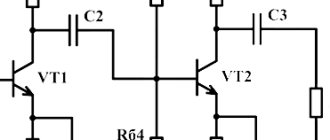
For example, a simple amplifier circuit with one transistor.
Input X1 plus (left or right channel), X2 minus. The sound signal is sent to electrolytic capacitor C1. It protects transistor VT1 from short circuiting, since transistor VT1 is constantly open using a voltage divider across R1 and R2. The voltage divider sets the operating point at the base of transistor VT1, and the transistor does not distort the input signal. Resistor R3 and capacitor C2, which are connected to the emitter of transistor VT1, perform the function of thermal stabilization of the operating point as the temperature of the transistor increases. Electrolytic capacitor C3 accumulates and filters the supply voltage. The BF1 dynamic head serves as an audio signal output.
Is it possible to understand this only by learning the designations of radio components without circuit design and theory? Unlikely.
The situation is even more complicated with digital technology.
What kind of microcontroller is this, what functions does it perform, what firmware and what fuses are installed in it? And the second microcircuit, what amplifier is it? Without datasheets and a description of the circuit, it will not be possible to understand its operation.
Study circuit design, theory and practice. Simply learning the names of the parts will not help you understand the circuitry. The designation of radio components can be learned on its own with practice and accumulation of knowledge. It all depends on the chosen industry. Signalmen have one circuit design, mobile equipment repairmen have another. And those who deal with sound will not really understand electricians. As well as vice versa. To understand another industry, its circuitry and operating principles, you need to immerse yourself in it.
Circuit diagrams are a kind of language that has different dialects.
Therefore, one should not create illusions. Study circuit design and assemble circuits.
Recommended reading: Debug board
Schematic diagrams help to assemble devices, and when studying the theory, to understand the operation of the device. Without knowledge and experience, a diagram is just a diagram.
Connection of resistors
In electronics and electrical engineering, resistor connections are often used in various combinations and configurations. For greater clarity, you should consider a separate section of the circuit with a series, parallel and mixed connection.
In a series connection, the end of one resistor is connected to the beginning of the next element. Thus, all resistors are connected one after another, and a total current of the same value flows through them. Between the start and end points there is only one path for current to flow. As the number of resistors connected into a common circuit increases, there is a corresponding increase in the total resistance.
A connection is considered parallel when the initial ends of all resistors are combined at one point, and the final outputs at another point. Current flow occurs through each individual resistor. As a result of parallel connection, as the number of connected resistors increases, the number of paths for current flow also increases. The total resistance in such a section decreases in proportion to the number of connected resistors. It will always be less than the resistance of any resistor connected in parallel.
Most often in radio electronics, a mixed connection is used, which is a combination of parallel and serial options.
In the diagram shown, resistors R2 and R3 are connected in parallel. The series connection includes resistor R1, a combination of R2 and R3, and resistor R4. In order to calculate the resistance of such a connection, the entire circuit is divided into several simple sections. After this, the resistance values are summed up and the overall result is obtained.
Types of Electronic Circuits
In radio electronics, there are several types of circuits: circuit diagrams, wiring diagrams, block diagrams, voltage and resistance maps.
Schematic diagrams
Such an electrical diagram gives a complete picture of all the functional components of the circuit, the types of connections between them, and the operating principle of electrical equipment. Circuit diagrams are commonly used in distribution networks. They are divided into two types:
- Single-line. This drawing shows only power circuits.
- Full. If the electrical installation is simple, then all its elements can be displayed on one sheet. To describe equipment that contains several circuits (power, measuring, control), drawings are made for each unit and placed on different sheets.
Block diagrams
In radio electronics, a block is an independent part of an electronic device. A block is a general concept; it can include both a small and a significant number of parts. A block diagram (or block diagram) gives only a general concept of the structure of an electronic device. It does not display: the exact composition of the blocks, the number of ranges of their functioning, the schemes according to which they are assembled. In a block diagram, blocks are represented by squares or circles, and the connections between them are represented by one or two lines.
The directions of signal passage are indicated by arrows. The names of the blocks in full or abbreviated form can be applied directly to the diagram. The second option is to number the blocks and decipher these numbers in a table located in the margins of the drawing. Graphic images of blocks can display the main parts or plot their operation.
Assembly
Wiring diagrams are convenient for creating an electrical circuit yourself. They indicate the location of each circuit element, communication methods, and the laying of connecting wires. The designation of radioelements on such diagrams usually approaches their natural appearance.
Voltage and resistance map
A voltage map (diagram) is a drawing in which, next to the individual parts and their terminals, the voltage values characteristic of the normal operation of the device are indicated. Voltages are placed in the gaps of the arrows, showing in which places measurements need to be made. The resistance map indicates the resistance values characteristic of a working device and circuits.