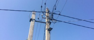
A solidly grounded neutral, which ensures its protective shutdown, helps protect a person from electric shock during emergency situations. This becomes possible due to potential equalization and operation of the device at the moment the current increases.
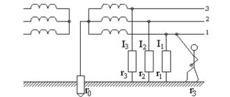
Scheme of solidly grounded neutral
You need to understand that the use of this mechanism in real life, just like with an insulated neutral, is strictly regulated by special rules for electrical installations (PUE).
Design and principle of operation of networks with solidly grounded neutral
The operating principle of electricity sources, in particular step-down transformers, is based on the law of mutual induction and energy transfer through a magnetic core. In this case, the primary winding may not have a neutral wire, in contrast to the secondary, where connecting it to zero through a conductor with low resistance, which can be equated with a zero value, will be an effective means of protecting a person from being hit by a voltage dangerous to his life and health.
The main feature of networks with a solidly grounded neutral is the appearance of not only linear, but also phase voltage. Let's look at what it is and how it differs from each other using a simple circuit diagram as an example.
Phase voltage is the potential between one of the line wires and the zero point connected to the ground, that is, tightly grounded. Line voltage is the potential difference between the two terminals of the lines, that is, L1 and L2, L1-L3, or L2-L3, it is also called phase-to-phase. Such sources of electrical energy in domestic conditions have a common voltage value in the form of 380 V - linear, and 220 - phase. Line voltage is greater than phase voltage by √3, that is, by 1.72.
But the main task of such a system is not only to transport voltages of two values to consumers with different numbers of phases in one power supply system, but also to protect people in the event of insulation breakdown and the appearance of voltage at points that normally do not have a dangerous potential. In residential buildings this is:
- the housings of all household appliances that conduct electric current, that is, made of steel or other conductive metal;
- metal structures of switchboard and distribution devices;
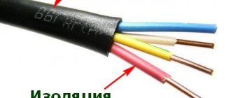
- protective sheath of cables.
Also, to ensure safety, all of the above elements must be grounded; in this case, the danger from the use of voltage and the use of household appliances in networks with a solidly grounded neutral will be minimal. Moreover, for such circuits, uniform distribution of single-phase loads is required.
What is grounded in electrical installations?
The requirements and rules for using protective grounding are compiled into a single document that regulates and determines the standardization of the entire process - GOST. Grounding, which ensures the protection of personnel and consumers from electric shock, is carried out strictly in accordance with the requirements of the PUE and the relevant GOST. Protective grounding of electrical installations provides for the electrical connection of the metal parts of electrical installations with the ground, and in its absence - with a conductor that replaces the ground. It should also be noted that those parts of the installations that have no other protection are grounded.
Thus, the metal casings of electrical units, devices, machines, cable couplings, lamps, sockets and switches, as well as the armor of cables and wires are grounded.
Explanation for dummies
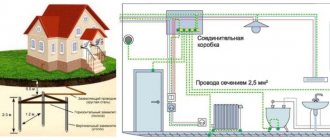
The step-down substation in which the transformer is installed has its own ground loop. It is interconnected by steel tires and rods into one grounding circuit. A cable containing four cores is laid to consumers in the electrical panel from the substation. If the consumer needs power from a three-phase 380 Volt circuit, then it must be connected to all conductors. In a single-phase 220 V network, power will be supplied from the neutral wire and from one of the phases. The protection of people in single-phase and three-phase circuits, if there is no grounding system, should be carried out using special residual current devices (RCDs), which are triggered by a small leakage to zero, while reliably disconnecting the consumer from the network.
PUE requirements
Today in electrical engineering both methods are quite actively used - solidly grounded and isolated neutral . The differences between them primarily lie in the way the transformer is connected to the grounding element. All necessary information on choosing a protection method is set out in the PUE.
If we talk about a 220 volt household network , then the grounding point can be located near the transformer, and a separate conductor is used to solve the problem. This will reduce the current path and at the same time reduce costs. In a country house, a connection with a metal frame of a building located deep in the ground is allowed.
If the grounding element is the foundation, then it must be connected to its reinforcement at at least two points.
Classification of networks with solidly grounded neutral
A modern power supply system has a standard marking where, in addition to the working neutral conductor, there is also a protective one, which determines the degree of protection.
- L - phase conductor;
- N—working zero;
- PE - protective neutral conductor;
- PEN - the working and neutral conductors are made of one wire.
There are several subsystems in circuits with an energy source that has a solidly grounded neutral:
- TN-C. With this system, the neutral and protective conductor from the substation are organized by one conductor; near the receiver, its housing (or other elements to be grounded) is connected to this combined conductor - this is called grounding. This is an outdated system, it was used in old houses during the USSR, but now it is not used for household consumers, as it is unsafe. Such a system has a significant drawback, since if the PEN conductor breaks on the path from the supply transformer to the power receiver, a dangerous potential appears on the grounded equipment housings. Used only to protect industrial consumers (discussed below in the next section).
- TN-S. Has a greater percentage of safety during emergency situations. This is achieved by separating the protective and working conductors along the entire length of the supply line, from the transformer to the electrical distribution panel (to the end consumer). However, due to the fact that it is necessary to use cable products with five cores, which greatly increases the cost of installation and the budget for organizing power supply to the consumer, this system is not always used.
- TN-CS. This grounding system is the most common in our time. With this system, the neutral and protective conductors along the entire length of the line are combined into one combined conductor PEN. At the entrance to the building, this conductor is divided into protective PE and zero N, which are then distributed to consumers (apartments). With this system, if the PEN conductor burns out to the separation point, a dangerous potential will appear on the grounded housings of electrical appliances. To prevent this, repeated grounding of the PEN conductor is made along the entire length of the line and at the entrance to the building and increased requirements are imposed on the mechanical protection of this conductor.
- TT. This grounding system is practiced if the TN-CS system line is in unsatisfactory technical condition and the protective grounding provided in it does not provide sufficient safety. This grounding system provides for the installation of an individual grounding loop at the consumer, while the PEN conductor of the electrical network is used only as the neutral wire N.
Operating principle of the TN-S grounding system
The electrical circuit for powering electrical appliances connected to the TN-S system is similar to the conventional power supply circuit that has been used since the times of Tesla and Edison. The difference lies in the presence of an additional wire connecting the equipment housing to the midpoint of the secondary winding of the transformer. The separation of neutral N and grounding PE makes it possible to prevent high voltage from reaching parts of electrical appliances not intended for this purpose.
In the TN-S grounding system, the neutral of the transformer is connected to grounding devices directly, without automatic circuit breakers or switches. Such a neutral is called “solidly grounded”.
According to GOST R 50571.1-2009 clause 312.2.1.1, there is no need to ground the PE conductor in the future. However, when installing this circuit, you should take into account the requirements of the PUE clause 7.1.87, according to which in the water shield this wire is connected to the EPS potential equation system.
To do this, the following elements are connected:
- PE wire coming from the transformer substation;
- steel communication pipes, including those in which cables are laid;
- metal elements of construction and engineering structures.
- casing of the introductory electrical panel and floor panels.
When the insulation breaks down, current begins to flow through the grounding to the housing, which causes the circuit breaker to trip. If it is insufficient to trigger the protection, then, due to grounding, there will be no voltage on the housing. This will avoid electrical injury, and the resulting leakage current will trigger the RCD.
Most household electrical appliances are connected to grounding in sockets with a grounding contact, to which a PE wire is connected during installation.
Important! In TN-S and TN-CS protective grounding systems, sockets are connected with a three-core cable. A wire with yellow or yellow-green insulation is connected to the grounding contact
Advantages of the TN-S system compared to other systems
Today, the TN-S protective grounding system provides the highest possible protection of people from electric shock. Its reliability can be further increased if you additionally install a potential equalization system and connect an RCD or automatic circuit breaker.
An additional advantage of this type of protection is that there is no need to install a ground loop in each house. Such groundings, according to PTEEP clause 2.7.9., require an annual check of their condition. Naturally, in most cases it is carried out formally or not at all, which does not make living in the house safer.
Another advantage is that all electronic equipment located in a metal grounded housing is protected from high-frequency interference. Such interference is created by electric shavers, vacuum cleaners, electric welding and other equipment. Therefore, this system is preferred by workers dealing with computer networks, television, sound recording and radar equipment.
The only, but significant, disadvantage of this system is its higher price, therefore it is possible to use an already installed TN-CS type grounding instead of the TN-S circuit.
Conclusion
To summarize the article, you can see that the TN-S system is the best existing type of grounding and should be used in all new power networks. If it is not possible to replace existing power lines with this scheme, the TN-CS scheme should be used.
Similar materials on the site:
- 5 grounding systems according to the PUE
- TT grounding system for a private house
It is important to know
To supply power to single-phase and three-phase consumers in industry and in domestic conditions, the so-called grounding is used, which “supposedly” is an effective method that ensures automatic shutdown of the electrical installation or part of it in which a short circuit has occurred. When grounding in circuits with a solidly grounded neutral, all metal parts and housings of electrical equipment are connected to the neutral wire. How does this protection work? The fact is that with any short circuit to the body, the circuit goes into short circuit mode, the current in the circuit breaker circuit increases greatly and the emergency section is disconnected from the network.
The advantage of such a system is the cost savings on protective grounding wiring, as well as the reduction in the cost of cable products, since single-phase and three-phase electrical receivers can be connected to the same circuit.
However, the disadvantage of a solidly grounded neutral, organized according to the principle of protective grounding, can be called the insufficiency of providing human protection in case of breakdown of insulation on the body of an electrical device and the simultaneous break of the neutral wire, which is also protective. And this is a very important point - zeroing is a dangerous protective measure, therefore it is prohibited and should not be organized at home under any circumstances!
Modern power supply is still aimed more at safety, and therefore requires the installation of an RCD and a separate protective grounding circuit, through which even the smallest leakage currents will go into the ground, without endangering a person.
Now you know what a solidly grounded neutral is, what its operating principle is and in what networks it is used. If you have any questions, you can ask them in the comments below the article!
What it is
The definition of “isolated neutral” is given in Chapter 1.7. PUE, in paragraph 1.7.6. and GOST R 12.1.009-2009. Where it is said that the neutral of a transformer or generator is called isolated when it is not connected to a grounding device at all, or when it is connected through protection, measurement, and alarm devices.
The neutral is the point at which the windings of transformers or generators are connected when switched on in a star configuration.
There is a misconception among electricians that the abbreviated name for an insulated neutral is an IT system, according to the classification of clause 1.7.3. Which is not entirely true. The same paragraph states that the designations TN-C/CS/S, TT and IT are accepted for networks and electrical installations with voltages up to 1 kV.
In the same chapter 1.7 of the PUE there is paragraph 1.7.2. where it is said that with regard to electrical safety measures, electrical installations are divided into 4 types - isolated or solidly grounded up to 1 kV and above 1 kV.
Thus, there are some differences in the safety and application of such a network in different voltage classes, and calling a 10 kV line with an isolated neutral “IT system” is at least incorrect. Although schematically it’s almost the same.
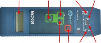
Equipment and tools for measuring ground resistance
The main instrument used to measure resistance to spreading currents is the IS-10 grounding meter. This device operates in five measurement ranges, which explains its wide application. The minimum range is 0.01 to 9.99 ohms, followed by 0.1 to 99.9 ohms, 1 to 999 ohms, 0.01 to 9.99 kohms. The maximum resistance determined by this device is in the range from 1 to 999 mOhm. In combination with the measuring device, remote current and potential electrodes are used.
It should be noted that the grounding measuring circuit is assembled according to strict rules - the connecting conductors of the device, first of all, to the current and potential electrodes, then to the device and lastly to the ground electrode.
Invite to tender
If you have a tender and need more participants:
Select from the list the type of work that interests youIndustrial safety auditIdentification and classification of hazardous production facilities, obtaining a license to operate hazardous production facilitiesDevelopment of plans, action plans, documentation related to the readiness of enterprises for civil emergency situations and fire safetyInspection and examination of the industrial safety of buildings and structuresWork on lifting structuresWork on boiler inspection and power equipment facilitiesWorks at gas supervision facilities Work at chemical and petrochemical facilities Work at facilities related to the transportation of hazardous substances Work at production facilities for the storage and processing of plant raw materials Work at metallurgical foundries Work at mining plants Conformity assessment of elevators, technical examination of elevators Development of a safety justification for a hazardous production facility Development of documentation for an industrial safety management system Development of industrial safety declarations securityWork at the facilities of the Ministry of Defense (special purpose production of military units) and the facilities of the Federal Penitentiary Service of Russia (special purpose organization of correctional institutions) Design Repair and installation work Repair of automobile lifting equipment Electrical repair and electrical measuring work Development and production of safety devices for industrial facilities Development and production of non-standard metal products and equipment Non-state examination of design documentation (engineering surveys) Pre-certification training according to safety rules and standards Vocational training (blue-collar professions) Training in labor protection, fire safety and electrical safety, heat power engineering Special assessment of working conditions (SOUT) (until 2014 certification of workplaces)Accreditation and certification in the industrial safety examination systemCertification of equipment, declaration of conformityEnergy auditDevelopment of heat supply and water supply schemesOther workAdvanced training, professional retrainingInspection of shelvingCopy the link to your tender into this field, to do this, go to the browser, open your site, highlight and copy the address line, then paste into this field. If it doesn’t work out, just write the tender number and the name of the site. personal data